




Contact us
Call
Call us at
Available 9 AM - 5 PM CET Business Days
Download
Download Manuals, Datasheets, Software and more:
Feedback
Arbitrary Function Generators
AFG31000 Series Datasheet
More Information
- AFG31000 Arbitrary Function Generator
- Product Support
- Explore more Signal Generator models
Read Online:
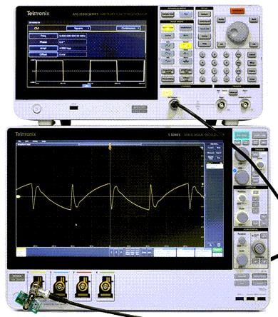
AFG31000 Series Datasheet
Overview
Key performance specifications
1 or 2 channel models
Output amplitude range 1 mV
P-P to 10V P-P into 50Ω loads Basic (AFG) mode:
25 MHz, 50 MHz, 100 MHz, 150 MHz, or 250 MHz sine waveforms
250 MSa/s, 1 GSa/s or 2 GSa/s sample rates
14-bit vertical resolution
Built-in waveforms include sine, square, ramp, pulse, noise, and other frequently used waveforms
Sweep, Burst, and Modulation modes (AM, FM, PM, FSK, and PWM)
Advanced (Sequence) mode:
Continuous mode (optional Sequence, Triggered and Gated modes)
16 Mpts arbitrary waveform memory on each channel (128 Mpts optional)
Up to 256 steps in sequence mode with loop, jump and wait events
Variable sampling clock 1 µSa/s to 2 GSa/s
Key features
Patented InstaView™ technology enables engineers to see the actual waveform at the Device Under Test (DUT) in real time, without the need of an oscilloscope and probe, eliminating the uncertainty caused by mismatched impedance
Sequencing option adds the ability to program long, complex waveforms with up to 256 steps
The 9-inch capacitive touch screen works like a smart phone and has short-cuts to frequently used settings
Built-in ArbBuilder lets you create and edit arbitrary waveforms on the instrument, eliminating the need to connect to a PC
Outputs are protected from over voltage and current to minimize potential instrument damage
Built-in Double Pulse Test application to generate voltage pulses with varying pulse widths onto the DUTs
Applications
Advanced research
Clock and system synchronization
Replication of real world signals
Component and circuit characterization and validation
Embedded circuit design and test
General purpose signal generation
Double pulse test
Basic and Advanced Modes
The AFG31000 series is the industry’s first arbitrary function generator with full function Basic (AFG) and Advanced (Sequence) modes.
In Basic mode, the AFG31000 generates traditional functions and arbitrary waveforms. The touchscreen and front-panel controls make it simple to set up.
Basic mode lets you change frequency without the need to worry about waveform length and sample rate. This feature is useful in analog designs that characterize filter/amplifier frequency responses or in digital designs where clock rates change frequently.
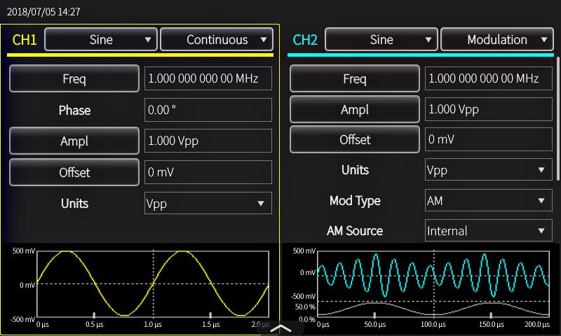 Figure 1. Key settings are visible at a glance, and are easy to adjust using touch, numeric keypad, or rotary controls
New with the AFG31000, Advanced mode provides the ability to generate multiple waveforms with complex timing. In this mode, you can compose a list (or a sequence) of 1 to 256 waveforms, with total waveform length up to 16 Mpts/ch (128 Mpts/ch optional) and define the output sequence of these waveforms. Repeat, go-to, wait, jump, and triggered events are all supported and the large memory provides space to store many waveforms or long waveforms.
This feature is very useful in applications where many test cases need to be performed sequentially. Instead of loading the test cases one by one, you can put all of them in a sequence and load at one time, switching from one to another seamlessly to greatly improve the test efficiency.
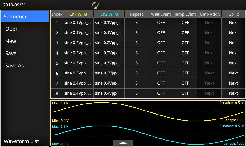 Figure 2. Advanced mode lets you build complex waveform sequences with flexible step controls.
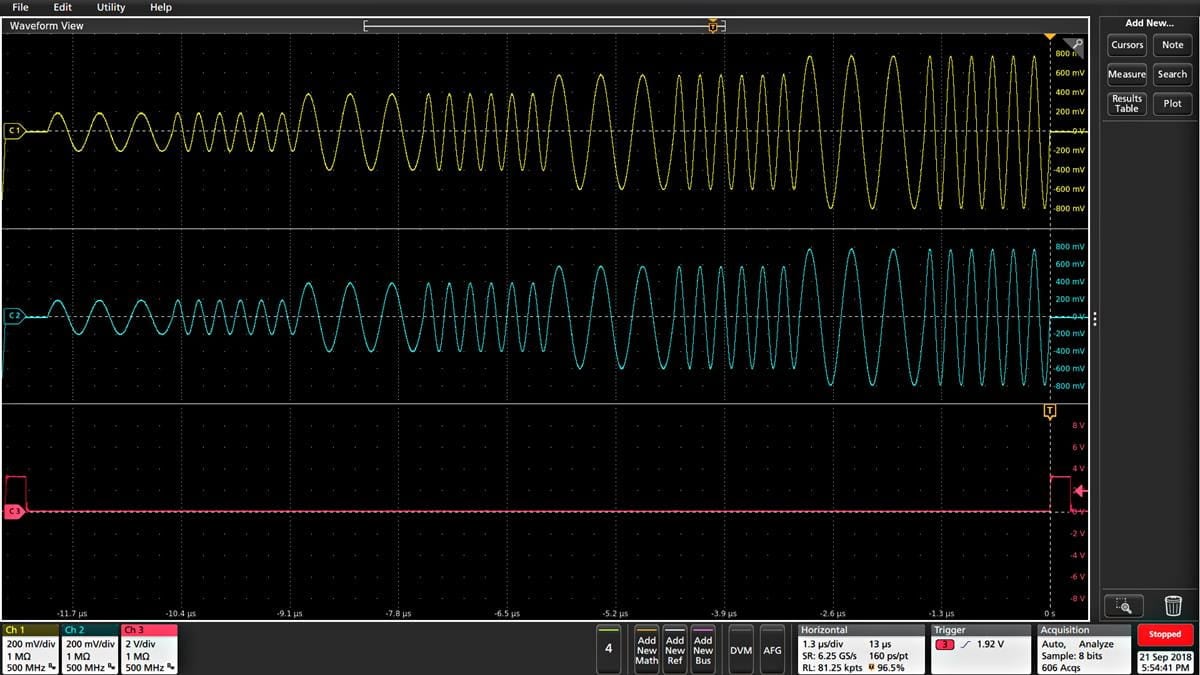 Figure 3. Sequenced sine waveforms with different frequency and amplitude.
Additionally, Advanced mode uses variable sample rate technology. Every sample in a waveform is output once and only once in each cycle, synchronized to the sample rate. Since there is no skipping or repetition, all details in the waveforms are kept. This feature is very useful for applications in which signal fidelity is extremely critical, such as IQ modulation and pulse train generation.
InstaView™ technology shows the actual waveform at the DUT
Most waveform generators assume they are driving a 50 Ω impedance. However, most devices under test do not have a 50 Ω impedance. This mismatch results in an inconsistency between the waveform as set on the AFG and the signal at the DUT.
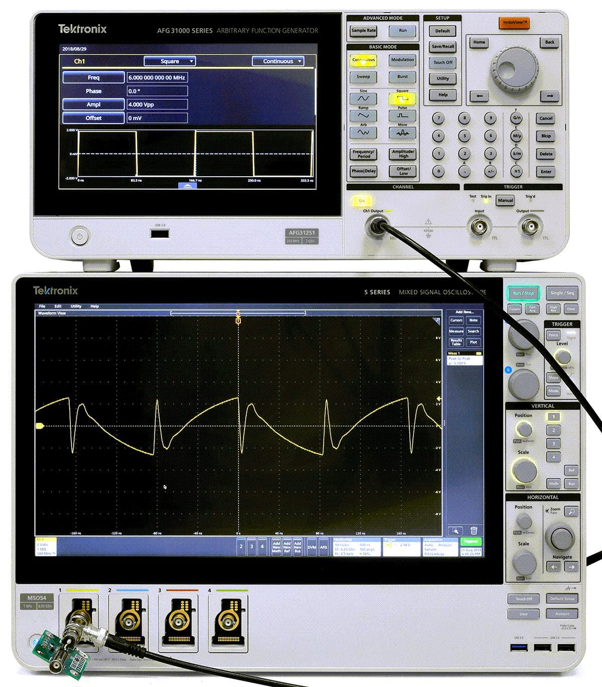 Figure 1. With InstaView turned off, the AFG31000 works like a traditional function generator. Due to an impedance mismatch, the AFG display shows a different waveform from the one observed at the DUT.
With the patented InstaView
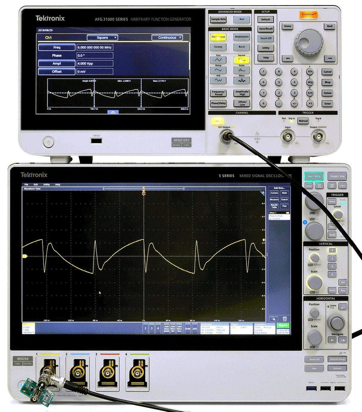 Figure 2. With InstaView turned on, the AFG31000 shows the waveform as observed at the DUT.
A large touch screen and smart user interface
The large 9-inch capacitive touch screen displays all related settings and parameters on a single screen. Similar to smart devices, you can tap or swipe to easily select, browse, locate and change settings and parameters. Frequently-used functions are immediately accessible. Familiar buttons and rotary knob controls are available for more traditional navigation.
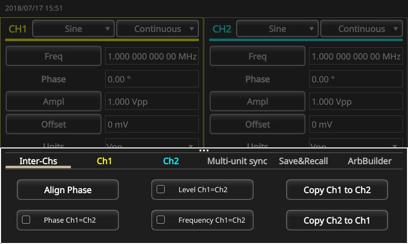 Figure 1. Frequently used settings are easy to access from the swipe-up menu.
Automate testing with KickStart software
Use KickStart to control your AFG31000 remotely and set up automated tests in four easy steps:
Select the AFG application.
Set up your instrument by selecting an AFG model and name (for example,
My AFG31252 ).Enter the test parameters.
Enable output to initiate signal generation.
KickStart provides built-in common waveforms like sine, square, pulse, ramp, and noise that you can simulate, or load a custom arbitrary function from a file on your PC or from the AFG. Then capture, export, and save your waveform settings.
Easily align and swap parameters between channels using the InterChannel settings for AFGs and tests using two channels.
Save the test parameters to visit later or take a screenshot of the tables and graphs directly from KickStart to use in your test reports.
Add the AFG application to your KickStart applications for Source Measure Units, Oscilloscopes, Data Acquisition Units, DMMs, and power supplies to complete your automated bench test solution. Learn more by visiting
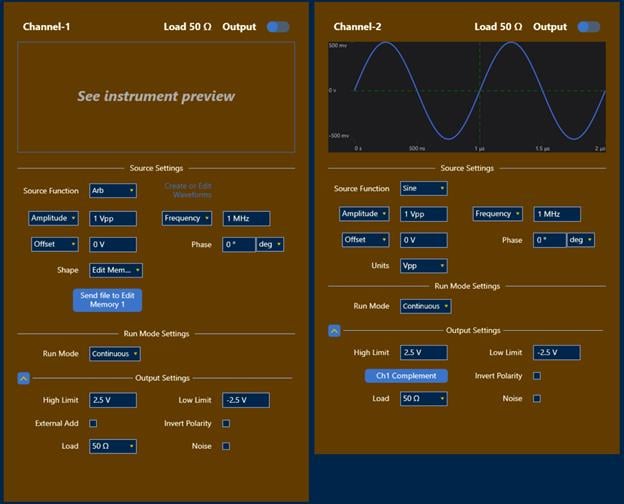

Built-in ArbBuilder tool makes creating and editing arbitrary waveforms easier than ever
ArbBuilder is a built-in application on the AFG31000 series that lets you create and edit your arbitrary waveforms directly on the generator. You can create arbitrary waveforms with the Equation Editor tool or start from a library of standard templates. Thanks to the large capacitive touch screen, you can drag, pinch and zoom to get the detail you need.
You can quickly replicate real-world waveforms captured with oscilloscopes or created by third-party software by loading CSV format data files directly into ArbBuilder from a USB memory stick.
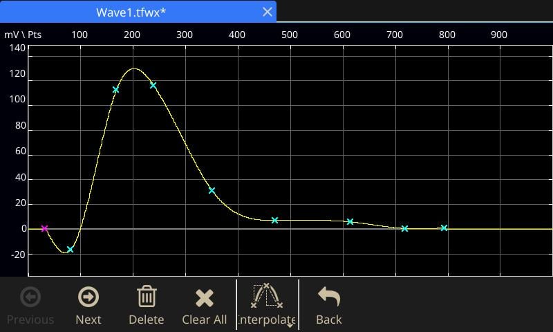 Figure 1. Create an arbitrary waveform using the easy touch screen interface.
Simplified multi-unit synchronization
Most applications need one or two channels of output, but some applications require more channels. For example, in order to simulate 3-phase power signals, engineers often need to synchronize three 2-channel generators; one for the voltage and current on each phase. To do this used to be time-consuming, as it required many cable connections between the AFG units, and making changes in deep branches of the menu trees on all instruments.
The AFG31000 simplifies this process with an onscreen wizard that leads you through the process of making cable connections and configuring settings to synchronize multiple generators.
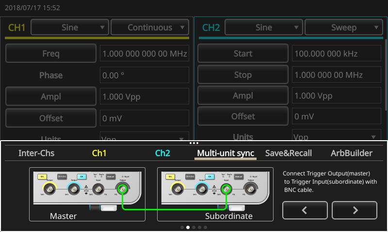 Figure 1. An on-screen wizard guides you through the process of multiple-unit synchronization.
Double Pulse Test
The AFG31000 includes Double PulseTest, a downloadable plugin software application that enables double pulse applications for the power and semiconductor markets. The Double Pulse Test user interface provides touch-and-swipe or point-and-click control for generating at least two varying pulse widths. These pulses can be output to an isolated gate driver to trigger power devices such as MOSFETs or IGBTs.
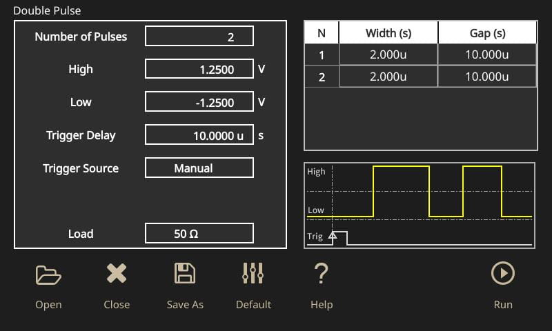 Figure 1. Double Pulse user interface
Ready-to-use, ease of use, built-in applications that reduce test development time
Generate pulses with varying pulse widths
Pulse widths from 20 ns to 150 μs
GUI and large touchscreen display
Multi-triggers method: Manual, Continuous and External
Up to 30 pulses
Ohm or High Z output modes
Free to download from the website
Works on all of the AFG31000 Series models
The Double Pulse Test on the AFG31000 offers the design and test engineer the ability to generate voltage pulses with varying pulse widths onto their DUTs. The design and test engineers are able to perform the Double Pulse Test in less than one minute, saving them hours when compared to using a PC software or a microcontroller to perform the test with varying configurations.
R&D engineer and test engineer of semiconductor industry (power device and power module with SiC/GaN/Si)
Automotive industry (EV, EHV, FCV), laboratory and university of power electronics
Power device manufacturer
Heavy user of power device and module
Inverter and motor drive system
Upgradability protects your investment
The AFG31000 provides upgrade options for bandwidth, memory extension, and sequence mode support. These options can be installed at the factory or at any time after purchase. This upgradability helps to reduce the product ownership threshold. And when your test requirements change, you can purchase and install upgrade software licenses to add higher performance features. Upgrades eliminate the concern about the return on investment during the instrument lifetime.
Specifications
All specifications are guaranteed unless noted otherwise. All specifications apply to all models unless noted otherwise.
Model overview
Model | Sine frequency range | Number of channels |
AFG31021 | 25 MHz | 1 |
AFG31051 | 50 MHz | |
AFG31101 | 100 MHz | |
AFG31151 | 150 MHz | |
AFG31251 | 250 MHz | |
AFG31022 | 25 MHz | 2 |
AFG31052 | 50 MHz | |
AFG31102 | 100 MHz | |
AFG31152 | 150 MHz | |
AFG31252 | 250 MHz |
Output characteristics
Amplitude
Characteristic | Description | |
|---|---|---|
Range | ||
AFG31021, AFG31022, AFG31051, AFG31052 | ||
AFG31101, AFG31102 |
| |
AFG31151, AFG31152, AFG31251, AFG31252 | AFG31251, AFG31252 at frequency >200 MHz to 250 MHz: 1 mV | |
Accuracy | ||
Resolution | ||
Units | V V | |
Output impedance | 50 Ω | |
Isolation | 42 V peak maximum to earth | |
Offset
AFG31021 | AFG31051 | AFG31101 | AFG31151 | AFG31251 | |
|---|---|---|---|---|---|
Range (into 50 | ±(5 V | ±(2.5 V | |||
Range (into open circuit or High-Z) | ±(10 V | ±(5 V | |||
Accuracy | ± (1% of |setting| +1 mV + 0.5% of Amplitude (V | ||||
Resolution | 1 mV or 4 digits | ||||
Output impedance | 50 Ω |
Load impedance setting | Selectable: 50 Ω, 1 Ω to 10.0 kΩ, High Z (adjusts displayed amplitude according to selected load impedance). |
Isolation | 42 |
Short-circuit protection | Signal outputs are robust against permanent shorts against floating ground. |
Overcurrent protection | When incoming current is greater than 250 |
General characteristics - Basic mode
Basic
Run modes | Continuous, Modulation, Sweep and Burst |
Standard waveforms | Sine, Square, Pulse, Ramp, More (Noise, DC,Sin(x)/x, Gaussian, Lorentz, Exponential Rise, Exponential Decay, Haversine) |
Arbitrary waveforms | Sampling clock: 250 MSa/s, 1 GSa/s or 2 GSa/s (model and waveform length apply) Vertical resolution: 14 bits Waveform length: 2 to 131,072 points |
Sine
Frequency range
AFG31021 | AFG31051 | AFG31101 | AFG31151 | AFG31251 | |
|---|---|---|---|---|---|
Continuous mode | 1 μHz to 25 MHz | 1 μHz to 50 MHz | 1 μHz to 100 MHz | 1 μHz to 150 MHz | 1 μHz to 250 MHz |
Burst mode | 1 μHz to 12.5 MHz | 1 μHz to 25 MHz | 1 μHz to 50 MHz | 1 μHz to 75 MHz | 1 μHz to 125 MHz |
Effective maximum frequency out
AFG31021 | AFG31051 | AFG31101 | AFG31151 | AFG31251 |
|---|---|---|---|---|
25 MHz | 50 MHz | 100 MHz | 150 MHz | 250 MHz |
Amplitude flatness (1 V
Frequency range | AFG31021, AFG31022, AFG31051, | AFG31151, AFG31152, AFG31251, AFG31252 |
|---|---|---|
< 5 MHz | ±0.2 dB | ±0.2dB |
≥ 5 MHz to 25 MHz | — | ±0.3 dB |
≥ 5 MHz to 100 MHz | ±0.3 dB | — |
> 25 MHz to 100 MHz | — | ±0.5 dB |
> 100 MHz to 200 MHz | — | ±1.0 dB |
> 200 MHz to 250 MHz | — | ±2.0 dB |
Amplitude flatness (1 V
AFG31021, AFG31022, AFG31051, AFG31052, | AFG31251, AFG31252 |
|---|---|
±0.1 dB | ≤ 150 MHz: ±0.1 dB > 150 MHz to 250 MHz: ±0.3 dB |
Harmonic distortion (1 V
Frequency range | AFG31021, AFG31022, AFG31051, AFG31052, AFG31101, AFG31102 |
|---|---|
10 Hz to <20 kHz | < −77 dBc |
≥20 kHz to <1 MHz | < −72 dBc |
≥1 MHz to <5 MHz | < −65 dBc |
≥5 MHz to ≤100 MHz | < −56 dBc |
Frequency range | AFG31151, AFG31152, AFG31251, AFG31252 |
|---|---|
10 Hz to < 1 MHz | < −72 dBc |
≥ 1 MHz to < 5 MHz | < −74 dBc |
≥ 5 MHz to < 25 MHz | < −69 dBc |
≥ 25 MHz to ≤ 250 MHz | < −37 dBc |
THD, typical
≤ 0.04%, 10 Hz to 20 kHz, 1 V
Spurious noise (1 V
Frequency range | AFG31021, AFG31022, AFG31051, AFG31052, |
|---|---|
≥ 10 Hz to < 1 MHz | < −78 dBc |
≥ 1 MHz to < 25 MHz | < −73 dBc |
≥ 25 MHz to ≤ 100 MHz | < −78 dBc |
Frequency range | AFG31151, AFG31152, AFG31251, AFG31252 |
|---|---|
10 Hz to < 1 MHz | < −80 dBc |
≥ 1 MHz to < 25 MHz | < −75 dBc |
≥ 25 MHz to ≤ 250 MHz | < −75 dBc + 6 dBc/octave |
Phase noise, typical
< −125 dBc/Hz at 20 MHz, 10 kHz offset, 1 V
Residual clock noise, all models
−63 dBm
Square
Frequency range
AFG31021 | AFG31051 | AFG31101 | AFG31151 | AFG31251 |
|---|---|---|---|---|
1 μHz to 20 MHz | 1 μHz to 40 MHz | 1 μHz to 80 MHz | 1 μHz to 120 MHz | 1 μHz to 160 MHz |
Rise/fall time, typical
AFG31021 | AFG31051 | AFG31101 | AFG31151 | AFG31251 | |
|---|---|---|---|---|---|
Amplitude ≤ 5 Vpp | ≤ 7.0 ns | ≤ 5.0 ns | ≤ 3.5 ns | ≤ 3.0 ns | ≤ 2.0 ns |
Amplitude > 5 Vpp | ≤ 8.0 ns | ≤6.0 ns | ≤ 4.2 ns | — | — |
Overshoot, typical
< 3%
Jitter (RMS), typical
2.5 ps
Ramp
Frequency range
AFG31021 | AFG31051 | AFG31101 | AFG31151 | AFG31251 |
|---|---|---|---|---|
1 μHz to 500 kHz | 1 μHz to 800 kHz | 1 μHz to 1 MHz | 1 μHz to 1.5 MHz | 1 μHz to 2.5 MHz |
Linearity, typical (1 kHz, 1 V
AFG31021 | AFG31051 | AFG31101 | AFG31151 | AFG31251 |
|---|---|---|---|---|
≤ 0.1% of peak output | ≤ 0.1% of peak output | ≤ 0.15% of peak output | ≤ 0.2% of peak output | ≤ 0.2% of peak output |
Symmetry
0% to 100%
Pulse
Frequency range
AFG31021 | AFG31051 | AFG31101 | AFG31151 | AFG31251 |
|---|---|---|---|---|
1 mHz to 20 MHz | 1 mHz to 40 MHz | 1 mHz to 80 MHz | 1 mHz to 120 MHz | 1 mHz to 160 MHz |
Pulse width
AFG31021 | AFG31051 | AFG31101 | AFG31151 | AFG31251 |
|---|---|---|---|---|
16 ns to 999.99 s | 10 ns to 999.99 s | 6 ns to 999.99 s | 4 ns to 999.99 s | 3 ns to 999.99 s |
Pulse width resolution
10 ps or 5 digits
Pulse Duty
0.001% to 99.999% (limitations of pulse width apply)
Edge transition time
AFG31021 | AFG31051 | AFG31101 | AFG31151 | AFG31251 |
|---|---|---|---|---|
8 ns to 0.625 * Pulse Period | 6 ns to 0.625 * Pulse Period | 4 ns to 0.625 * Pulse Period | 3 ns to 0.625 * Pulse Period | 2 ns to 0.625 * Pulse Period |
Edge transition time resolution
10 ps or 4 digits
Lead delay range
Mode | Characteristic |
|---|---|
Continuous | 0 ps to Period |
Burst | 0 ps to Period – [ Pulse Width + 0.8 * (Leading Edge Time + Trailing Edge Time)] |
Lead delay resolution
10 ps or 8 digits
Overshoot, typical
< 2%
Jitter (RMS), typical
2.5 ps
DC
Range (into 50 Ω)
AFG31021, AFG31022, AFG31051, AFG31052, AFG31101, AFG31102 | AFG31151, AFG31152, AFG31251, AFG31252 |
|---|---|
-5 V to 5 V | -2.5 V to 2.5 V |
Resolution (into 50 Ω)
1 mV or 4 digits
Accuracy
± (1% of | setting | +1
Noise
Bandwidth (−3 dB)
AFG31021, AFG31022, AFG31051, AFG31052, AFG31101, AFG31102 | AFG31151, AFG31152, AFG31251, AFG31252 |
|---|---|
150 MHz | 360 MHz |
Noise type
White Gaussian
Internal noise
Characteristic | |
|---|---|
Add | When activated, output signal amplitude is reduced to 50% |
Level | 0.0% to 50% of amplitude (V |
Resolution | 1% |
Other waveforms
Frequency range
AFG31021 | AFG31051 | AFG31101 | AFG31151 | AFG31251 |
1 μHz to 500 kHz | 1 μHz to 800 kHz | 1 μHz to 1 MHz | 1 μHz to 1.5 MHz | 1 μHz to 2.5 MHz |
Arbitrary waveforms
Frequency range
AFG31021 | AFG31051 | AFG31101 | AFG31151 | AFG31251 | |
|---|---|---|---|---|---|
Normal | 1 mHz to 12.5 MHz | 1 mHz to 25 MHz | 1 mHz to 50 MHz | 1 mHz to 75 MHz | 1 mHz to 125 MHz |
Burst mode | 1 mHz to 6.25 MHz | 1 mHz to 12.5 MHz | 1 mHz to 25 MHz | 1 mHz to 37.5 MHz | 1 mHz to 62.5 MHz |
Effective analog bandwidth (−3 dB)
AFG31021, AFG31022, AFG31051, AFG31052, AFG31101, AFG31102 | AFG31151, AFG31152, AFG31251, AFG31252 |
|---|---|
150 MHz | 360 MHz |
Waveform length
2 to 131,072
Sample rate
AFG31021 | AFG31051 | AFG31101 | AFG31151 | AFG31251 | |
|---|---|---|---|---|---|
Waveform length ≤ 16,384 | 250 MSa/s | 1 GSa/s | 1 GSa/s | 2 GSa/s | 2 GSa/s |
Waveform length > 16,384 | 250 MSa/s | 250 MSa/s | 250 MSa/s | 250 MSa/s | 250 MSa/s |
Vertical resolution
14 bit
Rise/fall time, typical
AFG31021 | AFG31051 | AFG31101 | AFG31151 | AFG31251 | |
|---|---|---|---|---|---|
Amplitude ≤ 5Vpp | ≤ 3.5 ns | ≤ 3.5 ns | ≤ 3.5 ns | ≤ 2 ns | ≤ 2 ns |
Amplitude > 5Vpp | ≤ 4.2 ns | ≤ 4.2 ns | ≤ 4.2 ns | ----- | ----- |
Jitter (RMS), typical
2.5 ps
Modulation
AM, FM, PM
Specification | Characteristic |
|---|---|
Carrier | All except pulse, noise, DC |
Source | Internal or external |
Internal modulating waveform | Sine, Square, Ramp, Noise, ARB (maximum waveform length: AM 4,096 pts; FM/PM/PWM 2,048 pts) |
Internal modulating frequency | 1 mHz to 1 MHz |
AM modulation depth
0.0 % to 120 %
AM modulation resolution
0.1%
Minimum FM peak deviation
DC
Maximum FM peak deviation
AFG31021 | AFG31051 | AFG31101 | AFG31151 | AFG31251 | |
|---|---|---|---|---|---|
Sine | 12.5 MHz | 25 MHz | 50 MHz | 75 MHz | 125 MHz |
Square | 10 MHz | 20 MHz | 40 MHz | 60 MHz | 80 MHz |
Arb | 6.25 MHz | 12.5 MHz | 25 MHz | 37.5 MHz | 62.5 MHz |
Others | 250 kHz | 400 kHz | 500 kHz | 750 kHz | 1.25 MHz |
PM phase deviation range
0° to 180°
PM phase resolution
0.1°
FSK
Specification | Characteristic |
|---|---|
Carrier | All except pulse, noise, DC |
Source | Internal or external |
Number of keys | 2 |
Internal key rate | 1 mHz to 1 MHz |
PWM
Specification | Characteristic |
|---|---|
Carrier | Pulse |
Source | Internal or external |
Internal modulating waveform | Sine, Square, Ramp, Noise, ARB (maximum waveform length: 2,048 pts) |
Internal modulating frequency | 1 mHz to 1 MHz |
Deviation range | 0% to 50.0% of pulse period |
Sweep
Type
Linear, Logarithmic
Waveforms
All, except Pulse, Noise, DC
Sweep time
1 ms to 500 s
Hold/return time
0 s to 500 s
Maximum total sweep time
500 s accuracy, typical: ≤ 0.4%
Minimum start/stop frequency
All except ARB: 1 μHz
ARB: 1 mHz
Maximum start/stop frequency
AFG31021 | AFG31051 | AFG31101 | AFG31151 | AFG31251 | |
|---|---|---|---|---|---|
Sine | 25 MHz | 50 MHz | 75 MHz | 125 MHz | 250 MHz |
Square | 20 MHz | 40 MHz | 80 MHz | 120 MHz | 160 MHz |
Arb | 12.5 MHz | 25 MHz | 50 MHz | 75 MHz | 125 MHz |
Others | 500 kHz | 800 kHz | 1 MHz | 1 MHz | 2.5 MHz |
Burst
Waveform
All except Noise, DC
Type
Triggered, gated
Burst count
1 to 1,000,000 cycles or Infinite
Internal trigger rate
1 μs to 500.0 s
Gate and trigger sources
Internal, external, remote interface
InstaViewTM
Waveforms
All except noise
Cable (channel output to load)
50 Ω BNC to BNC
Run mode
Continuous in Basic mode
Maximum measurement range (DC + peak AC voltage)
AFG31021, AFG31022, AFG31051, AFG31052, AFG31101, AFG31102 | AFG31151, AFG31152, AFG31251, AFG31252 |
|---|---|
−10 V to 10 V | −5 V to 5 V |
DC level measurement
Specification | Characteristic |
|---|---|
Accuracy (into 50 | ± (2 % of |setting| + 20 mVpp) |
Resolution | 1 mV or 4 digits |
Amplitude measurement
Specification | Characteristic |
|---|---|
Accuracy (sine, 1 kHz, 1 V | ± (2 % of setting + 20 mV) |
Resolution | 1 mV or 4 digits |
Bandwidth (−3 dB)
500 MHz
Flatness, sine, 1 V
AFG31021 | AFG31051 | AFG31101 | AFG31151 | AFG31251 |
|---|---|---|---|---|
0 to 100 MHz: ±1 dB | 0 to 200 MHz: ±1 dB 200 MHz to 250 MHz: ±2 dB | |||
Cable propagation delay measurement, typical
Specification | Characteristic |
|---|---|
Range | 0 to 20 ns (approximately 4 m/13 feet in length) |
Accuracy, typical | ± 500 ps |
General characteristics - Advanced mode
Waveform memory size | 16 Mpts (128 Mpts optional) each channel |
Run mode | Standard: Continuous Optional: Sequence, Triggered, Gated |
Number of waveform entries | Continuous, Triggered, Gated: 1 Sequence: 1 to 256 |
Minimum waveform length | 168 pts |
Waveform granularity | 1 pt |
Vertical resolution | 14 bits |
Jump/trigger events | External trigger (rising or falling edge), manual trigger, timer, SCPI commands |
Repeat count | 1 to 1,000,000 or infinite |
Timer range | 2 µs to 3600 s |
Timer resolution | 4 ns or 8 digits |
Variable sampling rate
AFG31020 | AFG31051 | AFG31101 | AFG31151 | AFG31251 | |
Range | 1 µSa/s to 250 | 1 µSa/s to 500 | 1 µSa/s to 1 | 1 µSa/s to 2 | 1 µSa/s to 2 |
Accuracy | 10 | ||||
Resolution | 1 µSa/s or 12 digits | ||||
Rise/fall time, typical
AFG31021 | AFG31051 | AFG31101 | AFG31151 | AFG31251 |
|---|---|---|---|---|
Amplitude ≥ 5 V Amplitude < 5 V | ≤ 3.0 ns | ≤ 2.0 ns | ||
Overshoot, typical
< 2%
Level flatness, typical
(sine, 1 V
Frequency range | All models |
|---|---|
< 5MHz | ±0.3 dB |
≥ 5 MHz to 25 MHz | ±0.5 dB |
≥ 25 MHz to 50 MHz | ±0.6 dB |
≥ 50 MHz to 100 MHz | ±1.0 dB |
≥ 100 MHz to 150 MH | ±1.5 dB |
≥ 150 MHz to 250 MHz | ±2.3 dB |
Harmonic distortion, typical
(sine with 64 pts/cycle, 1 V
AFG31021 | AFG31051 | AFG31101 | AFG31151 | AFG31251 |
< -76 dBc at 250 MSa/S or 3.90625 MHz | < -67 dBc at 500 MSa/S or 7.8125 MHz | < -61 dBc at 1 GSa/S or 15.625 MHz | < -63 dBc at 2 GSa/S or 31.25 MHz | < -63 dBc at 2 GSa/S or 31.25 MHz |
Spurious, typical
(sine with 64 pts/cycle, 1 V
AFG31021 | AFG31051 | AFG31101 | AFG31151 | AFG31251 |
< −81 dBc at 250 | < −74 dBc at 500 MSa/S or 7.8125 MHz | < −75 dBc at 1 GSa/S or 15.625 MHz | < −64 dBc at 2 GSa/S or 31.25 MHz | < −64 dBc at 2 GSa/S or 31.25 MHz |
Spurious free dynamic range, typical
(sine with 64 pts/cycle, 1 V
AFG31021 | AFG31051 | AFG31101 | AFG31151 | AFG31251 |
|---|---|---|---|---|
< −76 dBc at 250 MSa/S or 3.90625 MHz | < −67 dBc at 500 MSa/S or 7.8125 MHz | < −61 dBc at 1 GSa/S or 15.625 MHz | < −63 dBc at 2 GSa/S or 31.25 MHz | < −63 dBc at 2 GSa/S or 31.25 MHz |
Phase noise, typical
(sine with 64 pts/cycle, 1 V
AFG31021 | AFG31051 | AFG31101 | AFG31151 | AFG31251 |
< −132 dBc at 250 | < −130 dBc at 500 | < −125 dBc at 1 | < −113 dBc at 2 | < −113 dBc at 2 |
Skew control
Range | −320 ns to 320 ns (channel 1 to channel 2 on dual channel models, at maximum sample rate) |
Resolution | 100 ps or 4 digits |
Accuracy, typical | ±(1% of | setting | + 500 ps) |
Initial skew, typical
< 500 ps
System characteristics
Output frequency resolution
Frequency accuracy | ±10 ±10 |
Aging | ±1.0 x 10 |
Phase
Range | −180° to +180° |
Resolution | 0.01° (sine) 0.1° (other waveforms) |
Remote program interface
GPIB, Ethernet 10BASE-T / 100BASE-TX / 1000BASE-T, USB 2.0
Maximum configuration times, typical
USB | LAN | GPIB | |
|---|---|---|---|
Function change | 61 ms | 61 ms | 63 ms |
Frequency change (except Pulse) | 3 ms | 4 ms | 6 ms |
Frequency change (Pulse) | 2.5 ms | 3 ms | 8 ms |
Amplitude change | 65 ms | 66 ms | 77 ms |
Select user ARB (4k points from USB Memory) | 43 ms | 40 ms | 53 ms |
Select user ARB (128k points from USB Memory) | 86 ms | 92 ms | 92 ms |
Data download time for 4k points | 36 ms | 21 ms | 21 ms |
Power source
Source | 100 115 V, 360 |
Consumption | 120 W |
Warmup time, typical
20 minutes minimum
Power on self diagnosis time
< 24 s
Acoustic noise
< 50 dBA
Display
9-inch capacitive touch screen with 800 × 480 resolution
User interface and Help languages
English, French, German, Japanese, Korean, Simplified and Traditional Chinese, Russian (user selectable)
Auxiliary input characteristics
External modulation input, channel 1 and channel 2
Input range
Characteristic | |
|---|---|
AM, FM, PM, PWM | ±1 V full range |
FSK | 3.3 V logic level |
Input impedance | 5.2 kΩ |
Frequency range | 125 kHz (1 MSa/s) |
External Trigger input
Level | TTL compatible |
Impedance | 10 kΩ |
Minimum pulse width | 100 ns |
Slope | Positive or negative selectable |
Trigger delay range | 0 ns to 85 s |
Trigger delay resolution | 100 ps or 5 digits |
Trigger latency, typical | 390 ns (trigger input to signal output, 1.5 μs for Advanced mode) |
Jitter (RMS), typical | 100 ps (signal output, with external trigger input in burst mode) |
10 MHz reference clock input
Impedance | 1 kΩ |
Input coupling | AC |
Required input voltage swing | 100 mV |
Lock range | 10 MHz ±35 kHz |
Channel 1 external add input
Impedance | 50 Ω |
Input range | −1 V to +1 V (DC + peak AC) |
Bandwidth | DC to 10 MHz (-3 dB) at 1 V |
Auxiliary output characteristics
Channel 1 trigger output
Level | Positive TTL level pulse into 1 kΩ |
Impedance | 50 Ω |
Jitter, RMS, typical | 10 ps for all models |
Output frequency
Characteristic | |
|---|---|
Waveform frequency < 4.9 | Same as the waveform frequency |
Waveform frequency ≥ 4.9 | A fraction of the waveform frequency |
Waveform frequency ≥ 50 | No output |
10 MHz reference clock out
Impedance | 50 Ω, AC coupled |
Amplitude | 1.2 V |
Physical characteristics
Dimensions
Height | 191.8 mm (7.55 in.) |
Width | 412.8 mm (16.25 in.) |
Depth | 143.3 mm (5.64 in.) |
Weight
Net | 4.7 kg (10.4 lb) |
Shipping | 7.0 kg (15.4 lb) |
EMC, environment, and safety
For indoor, non-residential use only.
Temperature
Operating | 0 °C to +50 °C |
Nonoperating | −30 °C to +70 °C |
Humidity
Operating | ≤ 80%, 0 °C to 40 °C ≤ 60%, > 40°C to 50°C, noncondensing |
Nonoperating | 5% to 90%, < 40 °C, noncondensing 5% to 80%, ≥ 40 °C to 60 °C, noncondensing 5% to 40%, > 60 °C to 70 °C, noncondensing |
Altitude
Operating | Up to 3,000 m (9,842 ft.) |
Nonoperating | Up to 12,000 m (39,370 ft.) |
EMC compliance
EN61326-1:2013, EN 61326-2-1:2013
European Union
EU Council Directive 2004/108/EC
Safety
UL 61010-1:2004
CAN/CSA C22.2 No. 61010-1:2004
IEC 61010-1:2001
Overtemperature protection
Instrument is protected from overtemperature by turning off outputs
Ordering Information
Models
AFG31021 | 1 μHz to 25 MHz sine wave, 1-channel arbitrary function generator |
AFG31022 | 1 μHz to 25 MHz sine wave, 2-channel arbitrary function generator |
AFG31051 | 1 μHz to 50 MHz sine wave, 1-channel arbitrary function generator |
AFG31052 | 1 μHz to 50 MHz sine wave, 2-channel arbitrary function generator |
AFG31101 | 1 μHz to 100 MHz sine wave, 1-channel arbitrary function generator |
AFG31102 | 1 μHz to 100 MHz sine wave, 2-channel arbitrary function generator |
AFG31151 | 1 μHz to 150 MHz sine wave, 1-channel arbitrary function generator |
AFG31152 | 1 μHz to 150 MHz sine wave, 2-channel arbitrary function generator |
AFG31251 | 1 μHz to 250 MHz sine wave, 1-channel arbitrary function generator |
AFG31252 | 1 μHz to 250 MHz sine wave, 2-channel arbitrary function generator |
Options
Factory options
MEM | Extends arbitrary waveform memory to 128 Mpts/ch in Advanced mode |
SEQ | Enables Sequence, Triggered and Gated modes in Advanced mode |
Feature upgrade after purchase
The AFG31000 products offer several ways to easily add functionality after the initial purchase.
Description (node locked licenses) | For one channel instruments | For two channel instruments |
|---|---|---|
Enables Sequence, Triggered, and Gated modes in Advanced mode | AUP-AFG3SEQ-1 | AUP-AFG3SEQ-2 |
Extends arb memory to 128 Mpts/ch in Advanced mode | AUP-AFG3MEM-1 | AUP-AFG3MEM-2 |
Bandwidth extension from 25 MHz to 50 MHz | AUP-AFG3BW25T50-1 | AUP-AFG3BW25T50-2 |
Bandwidth extension from 25 MHz to 100 MHz | AUP-AFG3BW25T100-1 | AUP-AFG3BW25T100-2 |
Bandwidth extension from 50 MHz to 100 MHz | AUP-AFG3BW50T100-1 | AUP-AFG3BW50T100-2 |
Bandwidth extension from 150 MHz to 250 MHz | AUP-AFG3BW150T250-1 | AUP-AFG3BW150T250-2 |
Power plug options
Language options
Opt. L0 | English front panel overlay (default) |
Opt. L1 | French front panel overlay |
Opt. L2 | Italian front panel overlay |
Opt. L3 | German front panel overlay |
Opt. L4 | Spanish front panel overlay |
Opt. L5 | Japanese front panel overlay |
Opt. L6 | Portuguese front panel overlay |
Opt. L7 | Simplified Chinese front panel overlay |
Opt. L8 | Traditional Chinese front panel overlay |
Opt. L9 | Korean front panel overlay |
Opt. L10 | Russian front panel overlay |
Opt. L99 | No front panel overlay |
Service options
Three Year Total Protection Plan, includes repair or replacement coverage from wear and tear, accidental damage, ESD or EOS plus preventative maintenance. Including a 5 day turnaround time and priority access to customer support.
Five Year Total Protection Plan, includes repair or replacement coverage from wear and tear, accidental damage, ESD or EOS plus preventative maintenance. Including a 5 day turnaround time and priority access to customer support.
Accessories are not covered by the instrument warranty and Service Offerings.
Accessories
Standard accessories
— | AFG31000 Series Arbitrary Function Generator Compliance, Installation, and Safety Instructions |
012-1732-xx | BNC cable shielded, 3 ft. |
174-4401-xx | USB cable, A to B, 3 ft. |
— | Power cord |
— | NIST-traceable calibration certificate |
Recommended accessories
012-1732-xx | BNC cable shielded, 3 ft. |
012-0991-xx | GPIB cable, double shielded |
011-0049-02 | 50 Ω BNC terminator |
ACD4000B | Soft transit case |
HCTEK54 | Hard transit case (requires ACD4000B) |
AFG31000-RMK | Rack-mount kit |
Warranty
Product warranty
Three-year warranty on parts and labor
| |
| |
|

Tektronix is registered to ISO 9001 and ISO 14001 by SRI Quality System Registrar. Product(s) complies with IEEE Standard 488.1-1987, RS-232-C, and with Tektronix Standard Codes and Formats. Product Area Assessed: The planning, design/development and manufacture of electronic Test and Measurement instruments.
75W-61444-3


