Contact us
Call us at
Available 6:00 AM – 5:00 PM (PST) Business Days
Download
Download Manuals, Datasheets, Software and more:
Feedback
Model, Measure, and Optimize Your High-Speed Signal Path
Accurate measurement of high-speed systems requires visibility across the entire signal path—from the transmitting DUT, through any probes and interconnects, to the receiver.
Tektronix Signal Integrity Modeling (opt. SIM) software integrates seamlessly with the 5 Series B MSO, 6 Series B MSO, and 7 Series DPO oscilloscopes. It lets you de-embed cables and fixtures, embed various channel loss profiles, and emulate receiver equalization or experiment with transmitter equalization directly on your oscilloscope.
Designed for early bring-up, compliance, and debug, SIM provides an intuitive user experience that helps you accelerate development and deliver high-performance products with confidence.
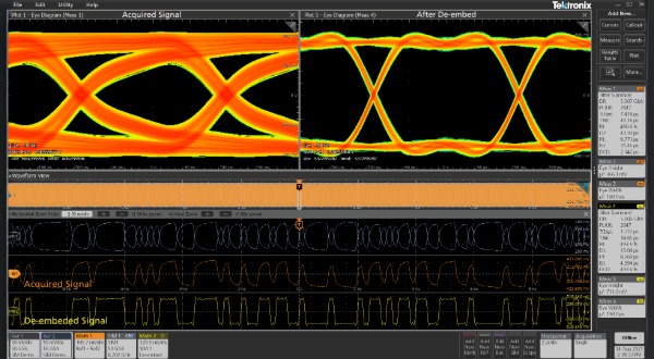
Effects of channel loss removed by de-embedding, resulting in a larger eye opening.
De-embed or Remove Signal Path Effects
At high frequencies, even well-designed setups introduce distortion—through probe loading, cable loss, and fixture reflections—that can obscure true DUT behavior in high-speed, RF, and fast-switching power designs.
Tektronix Signal Integrity Modeling (opt. SIM) software applies S-parameter de-embedding to reveal how the signal looks at the DUT—eliminating loss, reflections, and delay from the setup.
VDUT(f) = Vmeas(f) / H(f)
where H(f) is the transfer function (from the S-parameters) of the measurement path
De-embedding is especially critical when measurement artifacts overshadow DUT behavior, when direct probing is physically impractical, or when compliance requires visibility at standardized test points (TP0, TP1, TP2, etc.) —as defined for PCIe, USB, DDR, and more. SIM helps you virtually shift the measurement plane to where it matters.
Watch short demo video: De-embedding for Accurate Eye Diagrams
Embed Real-World Interconnect Characteristics
Whether you're exploring worst-case scenarios, comparing link configurations, or validating physical-layer compliance, embedding helps you confidently assess performance before deployment.
Embedding allows engineers to virtually insert real-world interconnects—such as backplanes, cables, or channels. SIM allows you to embed a worst-case cable or PCB assembly between a transmitter and receiver model to see how added insertion loss and reflections impact link margin at higher data rates.
With SIM, you can apply S-parameter models to simulate these environments directly on the oscilloscope, enabling margin analysis and signal integrity validation without needing to build or swap physical hardware.
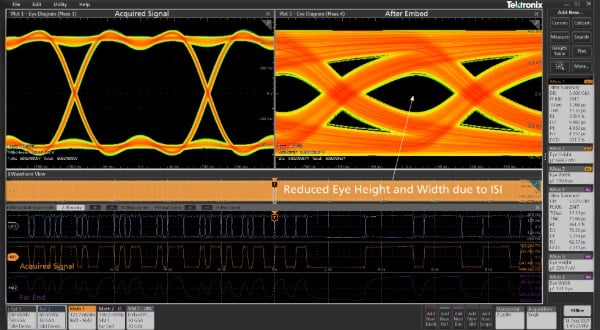
Reduced eye height and width due to ISI from embedded interconnect characteristics.
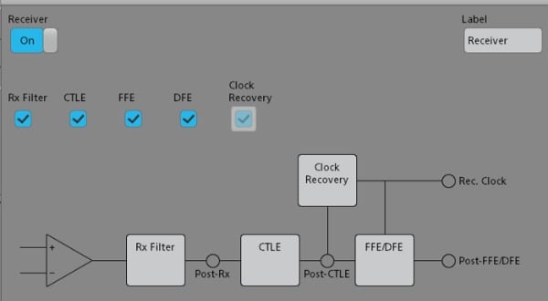
Configure receiver equalization in SIMA to emulate real-world behavior
Apply Equalization to Recover Closed Eyes and Validate Serial Link Performance
Equalization (EQ) compensates for channel loss and distortion to restore eye opening and recover timing and amplitude margin, while de-embedding/embedding mathematically removes or applies the measured effects of specific fixtures or interconnects. Used together, these tools reveal a clear, accurate view of a device’s true performance.
Use receiver equalization (Rx EQ) emulation when direct probing is impractical— embed the effects of a known channel, then apply Rx equalization (CTLE, FFE, DFE) to reconstruct the signal as it would appear at the decision point of the receiver.
Transmitter equalization (Tx EQ), allows you to condition the transmitted signal directly on the oscilloscope by applying pre-emphasis or de-emphasis to shape the signal before it enters the channel, predicting how different Tx settings impact overall signal integrity.
With SIM Advanced (opt. SIMA), emulate channel conditions, then apply and tune both Tx and Rx equalization models directly on the oscilloscope—enabling EQ optimization, “what-if” design exploration, and improved eye diagrams to pass high-speed serial standards tests.
Complete Visibility of the Signal Path
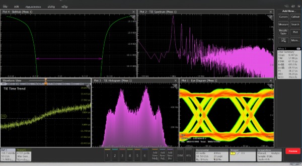
Move seamlessly from component level analysis—such as validating S-parameters or impedance, or visualizing system characteristics via Smith Charts—to comprehensive system level analysis of magnitude, phase, impulse, step response, jitter, and more.
Support for cascaded S-parameter models and virtually unlimited test points lets you simulate parallel paths and complex signal chains—helping you explore, iterate, and optimize with speed and precision.
Quickly de-embed fixtures, embed channel models, and apply equalization to see your signal as it truly is. Tektronix SIM software works with your oscilloscope to preserve both original and corrected results for rapid, side-by-side comparisons and confident “what-if” analysis.
Learn more about the Signal Integrity Modeling (opt SIM) software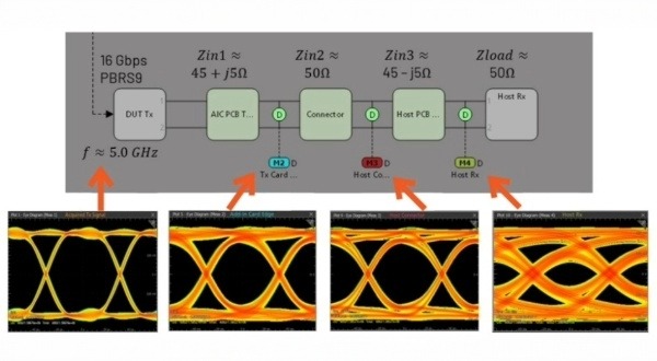
Configuration in SIM producing eye diagrams revealing increased signal distortion due to impedance discontinuities in the signal path.