


This application note is based on tests developed by Qorvo application engineering using a Tektronix 6 Series MSO. A 5 Series MSO can also be used. The operation of the two instruments is identical, although the 6 Series MSO generally provides lower noise. A goal of this application note is to conduct all double pulse test (DPT) measurements with a single oscilloscope plus benchtop DC power supplies, minimizing power and probing cabling. The DUTs are high-voltage, high-current and/ or high-power, so a clean and simple setup is critical for efficient, successful, and safe measurements.
The method for generating the double pulse gate drive signal, outlined in this application note, uses a PC-based Python script. The sample code, courtesy of Qorvo, is available at https://github.com/Qorvo/DPT-on-MSO6.
An "as-is" executable is also provided, but note that adjustments may be needed to accomadate your system.
It is widely expected that wide bandgap (WBG) devices, using Silicon Carbide (SiC) and Gallium Nitride (GaN) transistors will broadly replace traditional silicon based power MOSFETs and IGBTs in switch mode power electronics and motor controls, due to their higher switching speeds and lower power losses. To aid in the adoption of WBG devices, JEDEC formed the committee JC-70, Wide Bandgap Power Electronics Conversion Semiconductors, which publishes several standardized guideline documents.
In this young, fast-growing industry, engineers are working hard on developments including:
- Application circuits, such as electric vehicles (EVs), EV charging stations, EV on-board chargers (OBCs), wind and solar inverters, and industrial/data center power supplies
- WBG devices/semiconductors. Today, most major power semiconductor companies support WBG devices
- Measurement equipment vendors. Major measurement system vendors support WBG testing solutions
Double pulse testing provides several critical measurements to help validate and optimize power converter designs. These include:
- Switching loss: EON and EOFF These 2 parameters depend on ΔVDS/Δt and ΔIDS/Δt.Precise time alignment is critical. Nanosecond errors in capturing signals can result in incorrect results.
- Peak voltage: VDS(MAX) Voltage spikes across the drain-to-source of the FET which exceed the DC bus voltage are commonly encountered during high-current, high-speed hard-switching.
- Peak current: ID(MAX) Fast switching operation of WBG transistors causes sharp current spikes that stress devices and may reduce lifespan.
- Reverse recovery charge: QRR The reverse recovery behavior of MOSFETs and cascode FETs must be quantified to understand its contribution to total losses.
For this application note, WBG power device supplier Qorvo partnered with Tektronix to describe practical solutions on a real-world SiC DUT. With the acquisition of UnitedSiC, Qorvo has a strong focus on high voltage and very high current markets, such as electric vehicle (EV) power trains, renewable energy, and offline power supplies, where Qorvo's market-leading lowest drain-to-source ON resistance (RDS(ON)) SiC FETs delivers the most benefits.

Let us define "high power" SiC devices as those dealing with a range of 1 kV and 100 A, resulting in 100 kW of power. The nature of the high voltage, high current, and fast-switching systems that SiC transistors handle and serve, presents many challenges which do not occur in common 5 V or 12 V systems. Examples of these challenges are:
- Currents on the order of 100 A reveal PCB traces as parasitic resistance elements, contributing a noticeable IR drop
- Voltages on the order of 1000 V cause tiny parasitic capacitance to store significant charge, causing meaningful power loss from switching operations
- The fast-switching capability of SiC devices exposes all conductor elements as parasitic inductance elements, causing unwanted kick-back voltage bumps from switching operations
- Per Maxwell's observations, fast-switching capacitors and inductors cause electromagnetic activities such as EMI / EMC
- High-power measurement requires solid / firm probing with generally bulky probes and stout cables, yet the challenges mentioned above demand short connection lengths.
Another aspect of dealing with bulky probes and cables is safety. To avoid any accidental short-circuit events or damages, test setups must be kept neat and simple. - The inductive kick-back voltage, explained above, easily reaches 50 V to 60 V, which exceeds the maximum allowable peak voltage limits, from the ground, of most measurement equipment. This makes it harder to select a proper "measurement ground plane" in our test setups.
The fast switching of SiC devices includes high frequencies, necessitating accurate measurement of signals of at least 100 MHz or higher bandwidth (BW). This requires the use of oscilloscopes and probes rated for 500 MHz or greater.
Double Pulse Testing (DPT)
Overview
Fully validating a SiC or a GaN-based WBG device requires running both static and dynamic measurements. The preferred test method to measure the switching and diode reverse recovery parameters of WBG devices is the double pulse test.
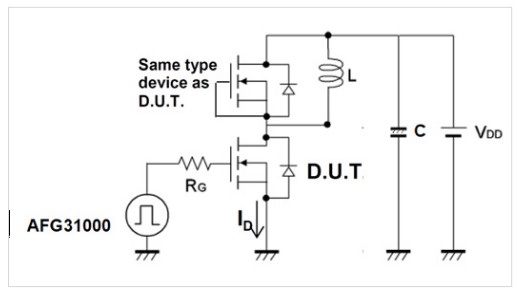
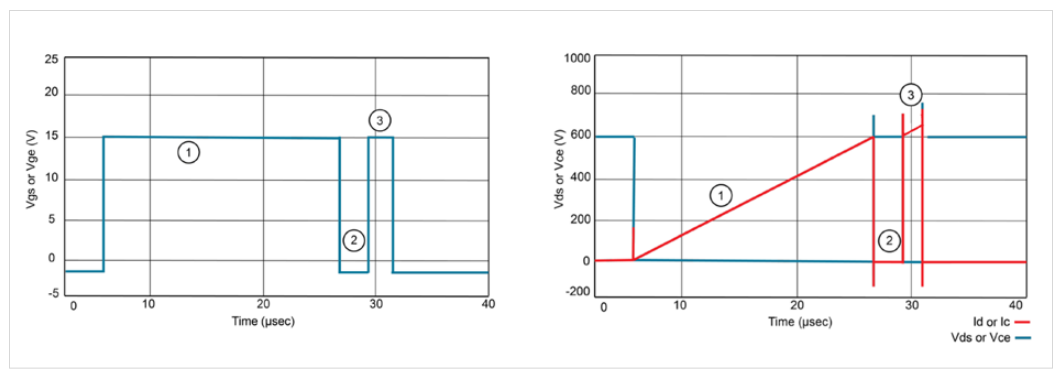
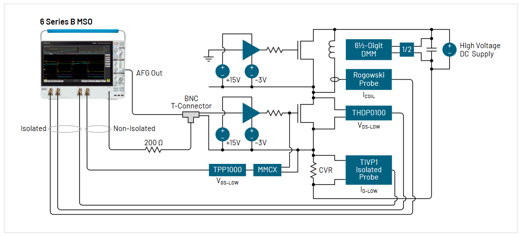
The DPT is an industry-standard technique for measuring a range of important parameters during turn-on, turn-off and reverse recovery on a WBG device under test. The basic test setup is shown in Figure 2. Assuming the same transistor devices are used for both the high side and low side, the high-side transistor can remain OFF and the switching losses and reverse recovery loss can be measured. To determine DPT switching parameters in the circuit, one must observe VDS, ID, and VGS on the low side device. Diode reverse recovery parameters are determined by measuring ID and VDS on the high side device. The DPT setup must generate at least two varying pulse widths into an isolated gate driver to trigger the FETs or IGBTs and control the conduction of current. These pulses may be generated by an arbitrary function generator (AFG). Figure 2 is simplified and does not show gate drivers. In a real application the AFG will typically feed isolated gate drivers, as shown in Figure 4. Figure 3 shows example DPT waveforms.
The Qorvo Test Setup
When testing a DUT in the 100 kW range, our highest concern is the safety of the operators running the DPT measurement.Safety measures are very important when working on a proof-of-concept prototype before establishing a repeatable, proven DPT board and setup. The most effective safety strategy is keeping our test setup simple by removing clutter such as cables and probe-heads.
As a user of 6 Series MSO oscilloscope, Qorvo realized that almost all required measurements can be made using the 6 Series with the installed AFG option. In short, the built-in AFG in the 6 Series may be used to generate the double pulse from its back-panel, as probes on its inputs may be used to gather signal information.
The benefits of using the proposed 6 Series MSO DPT setup are:
- Easily identify the measurement ground, which are all tied to chassis (earth) ground inside the 6 Series MSO, including:
– AFG output BNC cable ground
– Any non-isolated probe ground (shield/lead) - Simple wiring / cabling
- Full remote control capability of the 6 Series MSO from a PC. This allows probe cabling to be kept short, while allowing the test engineer to maintain distance from the test system during high-energy test procedures
To complete the measurement setup and take advantage of the AFG option in the 6 Series MSO, we must come up with a method for generating the DPT gate drive signals on the AFG.
Using Arbitrary Waveforms as Gate Drive Signals
This application note will offer a programmatic approach to automate the generation of gate drive signals with the 6 Series MSO's built-in AFG. Such an automated approach is recommended in the interest of speed, flexibility, and repeatability. However, for the purpose of understanding the program operation, it is useful to review the steps one would take in a manual process and the front-panel controls that correspond to the instrument commands used in the program.
To define a DPT signal, we need two pulses of different widths: the first longer pulse charges the coil to the target current and the second shorter pulse enables turn-on measurements before the coil current decays. To generate such a signal on the AFG, a custom waveform may be defined with the correct pulse widths. This custom waveform must be in Tektronix' ".wfm" or ".csv" format and may be constructed with spreadsheet software such as Microsoft Excel. Time and voltage pairs are specified to build a piece-wise-linear (X, Y) data pair format, and the file is saved as a ".csv" file.
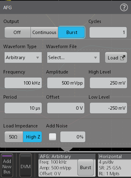
The AFG option in the 6 Series MSO can send a burst sequence with specified number repeats. From the front panel this is done by selecting Burst mode from the AFG Output control and setting the number of cycles. In this case, we will use the arbitrary waveform capability of the AFG to define the complete DPT gate drive signal (Figure 6) and set the burst mode to output 1 cycle of the signal.
To configure the AFG to use the custom waveform the Waveform Type must be set to Arbitrary and the Waveform File must be the custom waveform defined for the test. High and Low Level, as well as Period may be adjusted to suit the specific test at hand.
While it is possible to perform these operations manually, it is inconvenient to manually adjust pulse widths and load custom waveform files. A program developed at Qorvo greatly simplifies both waveform specification and setup of the AFG.
Connecting the Oscilloscope to the PC
To add physical distance from the test setup and improve safety, it is possible to connect the 6 Series MSO to a PC via an Ethernet LAN or USB. (Note that in some IT environments an Ethernet router may be required to define a small, isolated local network.)
When connected via LAN, 6 Series MSOs without Windows installed may be easily remotely controlled through the e*Scope web server. Instruments equipped with Windows may be controlled through Remote Desktop. In addition to this remote control capability, the LAN connection is used with the program introduced in this application note to upload our ".csv" file to the scope and generate the DPT signal.
The 6 Series MSO can also communicate over USB, and the DPT program in this application note can be used with USB. However, the e*Scope remote interface is not available over USB. Examples using both LAN and USB are given below.
The DPT program uses the PyVISA Python (language) library which supports most instrument interfaces. Thus the code can be adapted to support other instruments through interfaces such as RS-232 or GPIB.
PC-based Python Script for DPT on a 6 Series MSO with the Built-in AFG
As noted above, the source code for the script used in this application note is available for download from Qorvo's GitHub at https://github.com/Qorvo/DPT-on-MSO6.
(Note that an executable is also provided, but adjustments will probably be needed for your specific system.)
In short, the script may be used to identify instruments connected to the PC. It may then be used with the appropriate arguments to specify the width of the first ontime (Ton1), the first off-time (Toff1) and the second on-time (Ton2). The times are specified in microseconds. A third pulse may also be specified with a Toff2 and Ton3.
Based on the command line arguments, the script generates a set of ordered pairs in a CSV file and sends it to the oscilloscope's built-in AFG. As outlined above, the script also configures the AFG with the following settings:
- High impedance output
- Arbitrary function
- Output mode = Burst
- Burst count = 1
NOTE: Before running the program for the first time in a testing session, we strongly recommend to turn OFF your DUT power-bus supply to avoid any unwanted turn ON of the DUT due to pulse output from the AFG during the initial setup.
The script may be used in several ways, and examples of these use cases follow.
Program Usage 1: Listing Equipment
By running the program without any parameters / arguments, it lists all the equipment visible to your PC, as shown in Figure 7.
In this example, the target MSO64 is listed twice from both the USB and LAN interface ports since both are connected. The program will work equally well with LAN or USB in this situation. In this example, PyVISA also finds other instruments with ID 2 and 3.
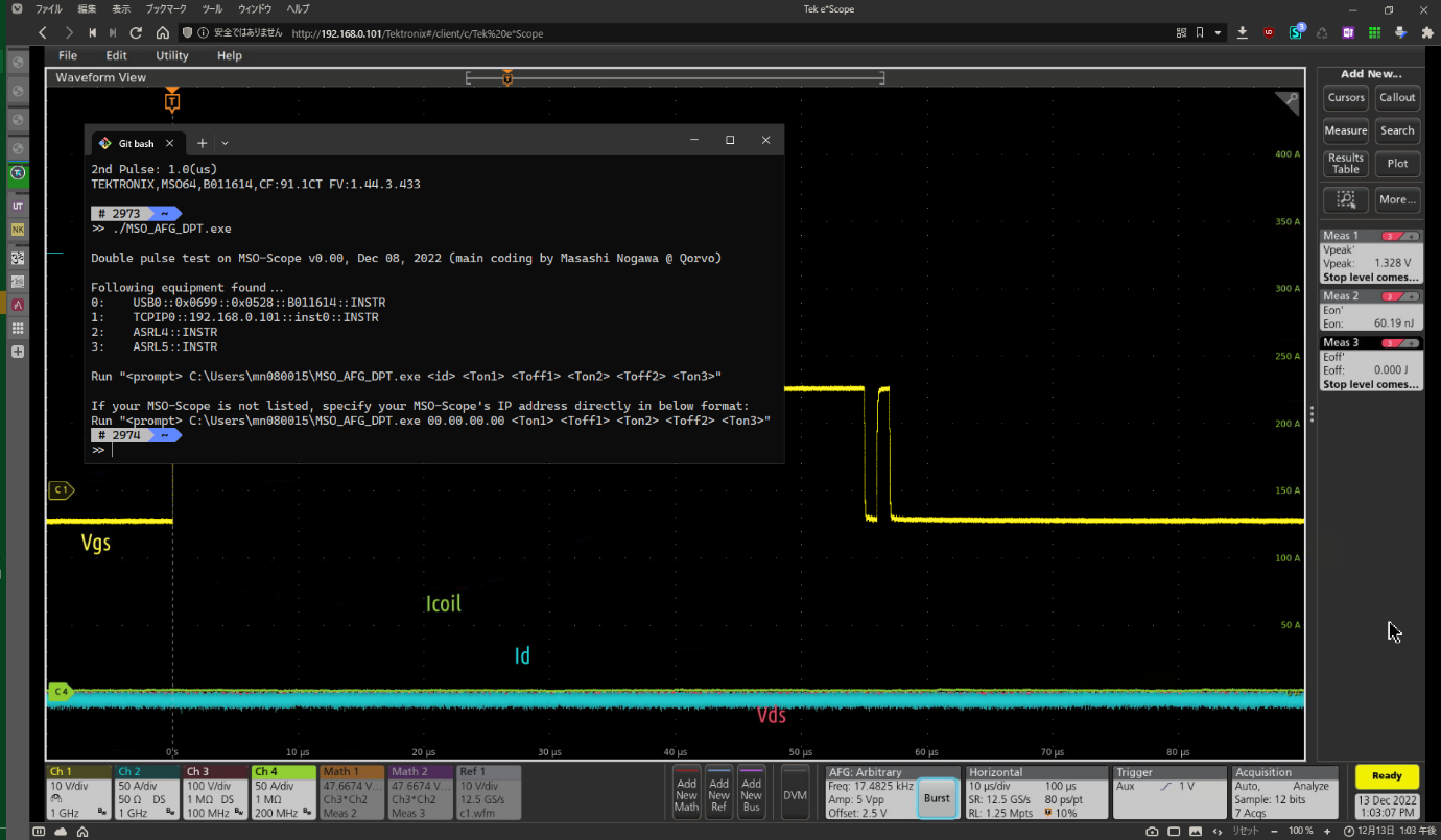
Program Usage 2: 2-Pulse DPT Setup via USB
By using the ID listed in the previous program execution, we can set up a DPT gate drive signal on the scope's built-in AFG over the USB interface.
In this example, shown in Figure 8, the following 2 steps were performed before the capture:
- Execute the program on the host PC command window: >> ./MSO_AFG_DPT.exe 0 55 1 1.
- Press the "Burst" button in the AFG badge on the 6 Series MSO to generate the burst.
The command line parameters "0 55 1 1" set up following double pulse drive signal on the AFG, as follows:
"0": Selects the USB interface of ID "0", from Figure 7
"55": Sets the first ON pulse width to 55 µs
"1": Sets the 1 µs OFF time between the first and second pulses
"1": Sets the second ON pulse width to 1 µs
Note that the same parameters are confirmed by the program in the command window.
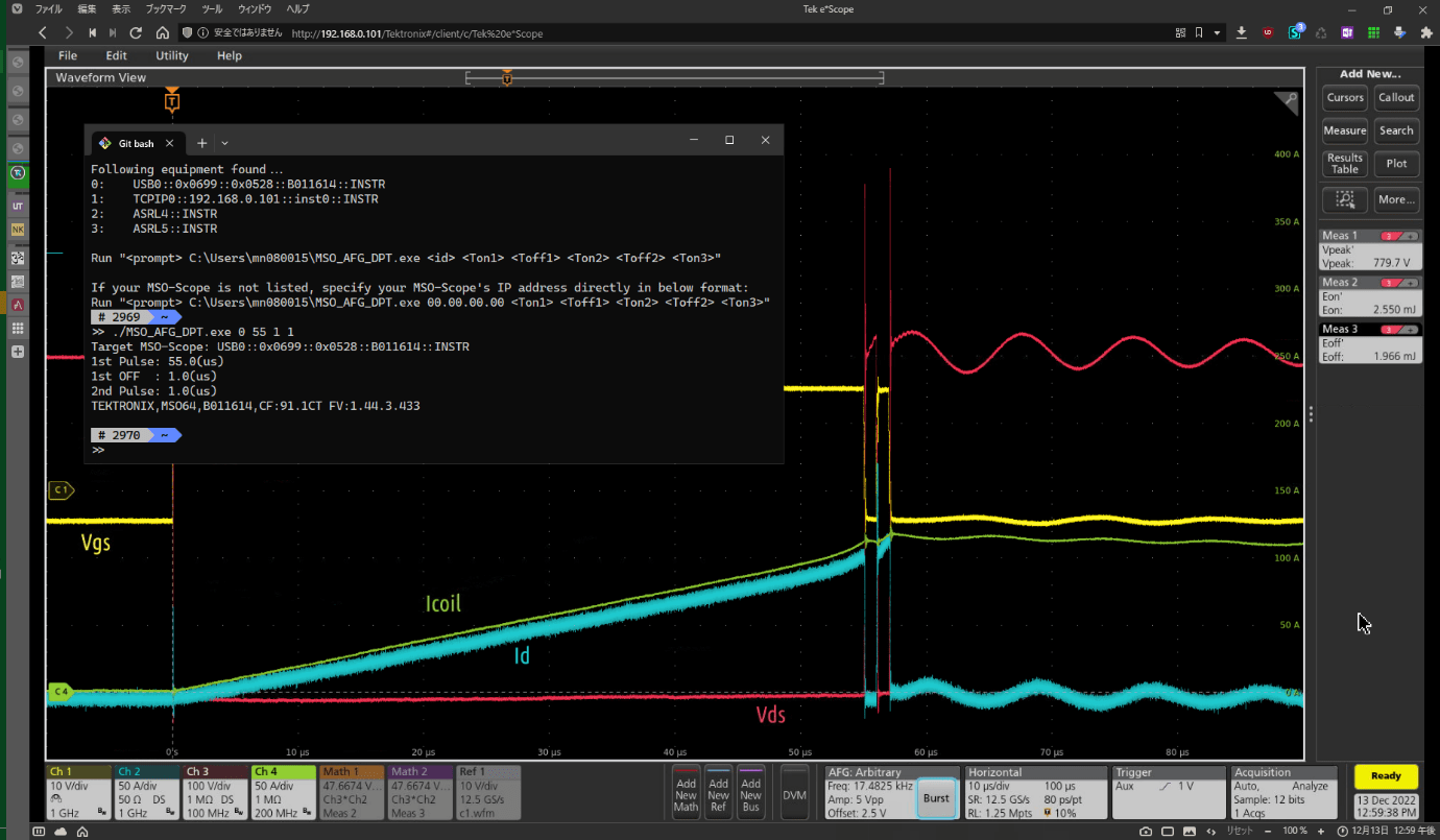
Program Usage 3: 2-Pulse DPT Setup via LAN
By specifying the IP address of the oscilloscope, we can set up a DPT on the AFG module on the scope.
The target oscilloscope will be identified by the program when it is on a local network. In this example setup, the program found the scope at ID = "1", as shown in Figure 7. However, if there are multiple routers in between the host PC and the target oscilloscope, the program will not find the scope. In this case the IP address must be specified to connect.
By opening the "I/O" setting dialog of the target scope from the "Utility" menu, you can identify your scope's IP address and use this IP address as the first parameter for the program. The IP address in this example is 192.168.0.101. The DPT parameters and subsequent steps are the same as the previous section "Program Usage 2: 2-Pulse DPT Setup via USB".

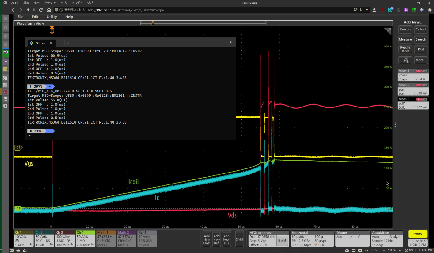
Program Usage 4: 3-Pulse DPT Setup
The program supports 3-pulse DPT by adding two additional parameters. This is shown in Figure 10.
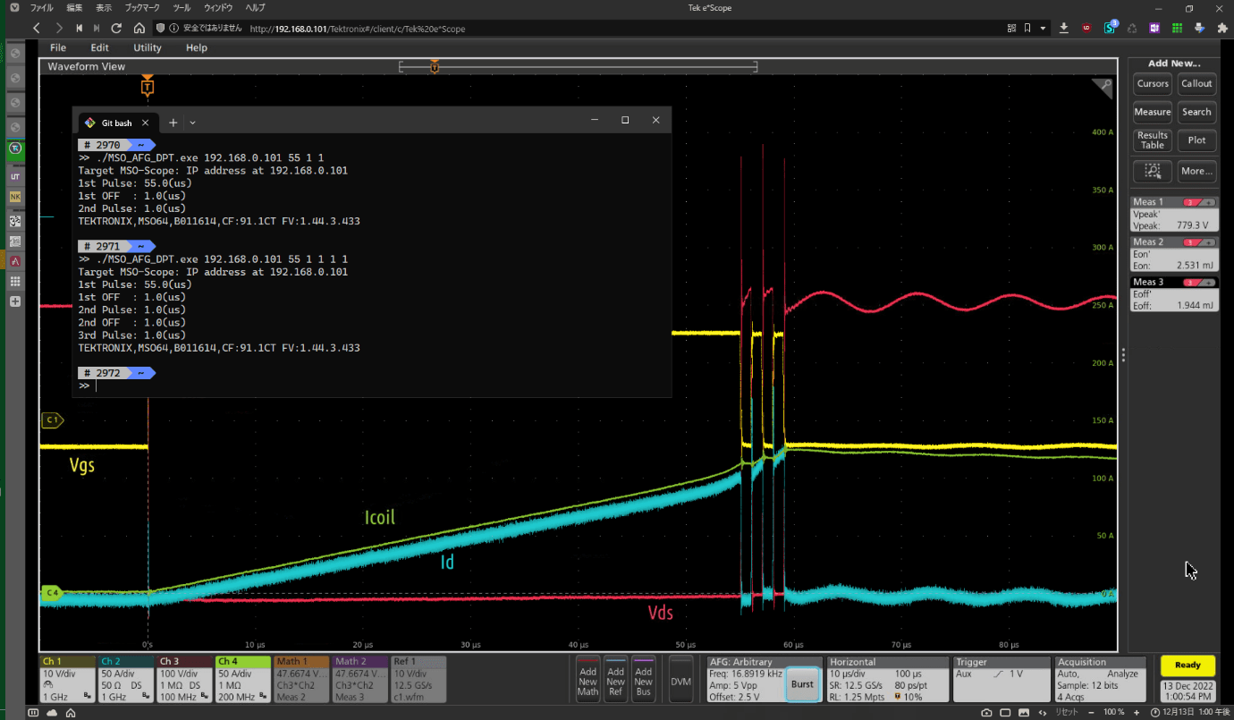
The program with "192.168.0.101 55 1 1 1 1" parameters sets up following DPT on the AFG:
"192.168.0.101": Specifies the IP address of the oscilloscope
"55": Sets the first ON pulse to 55 µs
"1": Sets 1 µs OFF time between the first and second pulses
"1": Sets the second ON pulse to 1 µs
"1": Sets 1 µs OFF between the second and third pulses
"1": Sets the third ON pulse to 1 µs
Again, the parameters are confirmed by the program in the command window.
Program Usage 5: 3-Pulse DPT Setup, with 100 ns resolution
The program supports pulse width control with 100 ns resolution.

In the example shown in Figure 11, the last parameter passed to the program is "0.5" for a 0.5 µs third pulse.
Figure 12 illustrates how the program handles parameter precision. In this case, the second OFF time is specified as 0.9501. The program rounds this to 1.0 µs.
An Example Test Run with Measurements
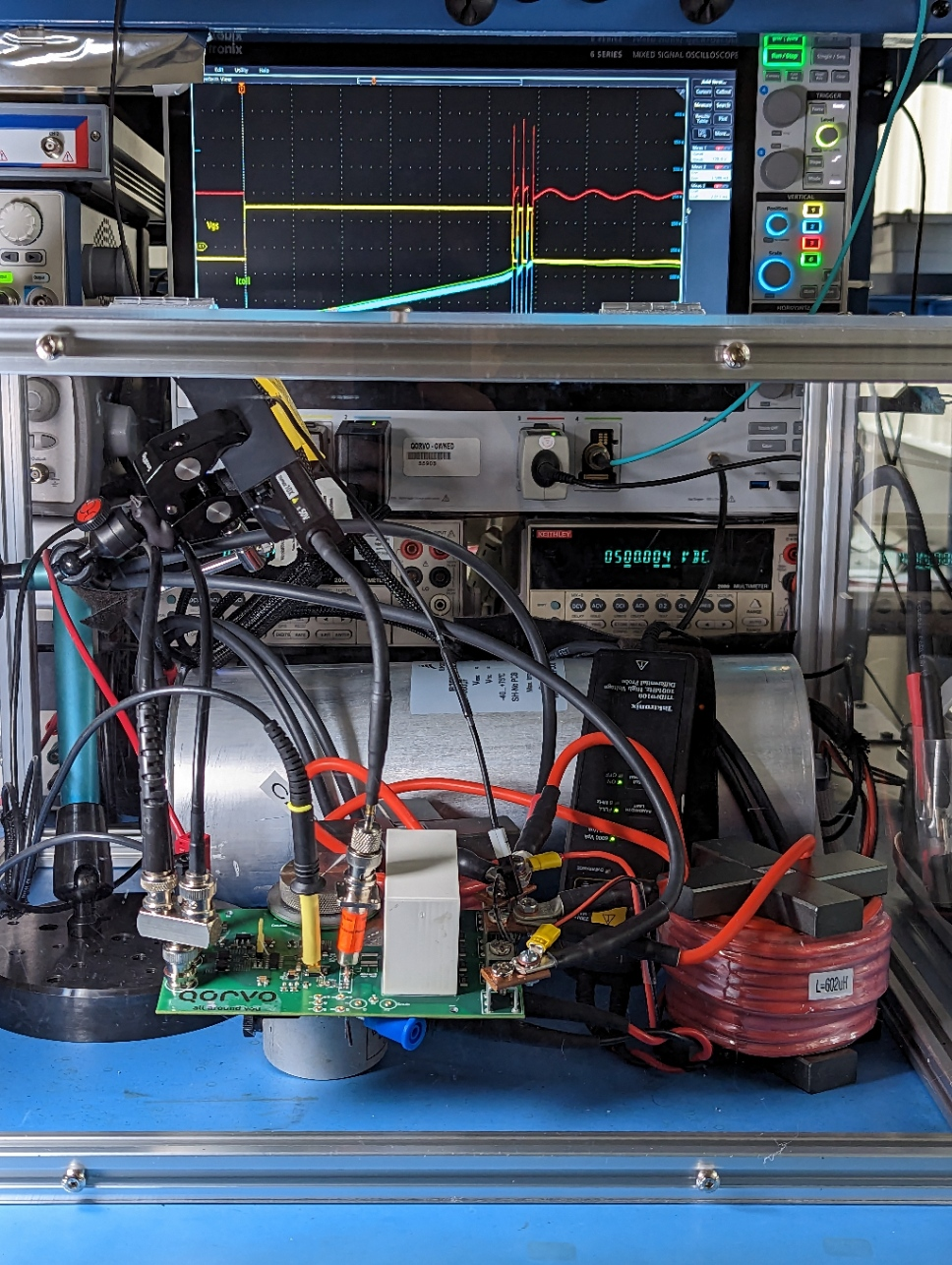
This section describes a typical DPT procedure on an actual DUT. All 6 Series MSO screenshots are captured from a Qorvo DPT test board as the DUT. The DUT and DPT setup information is given below:
- Qorvo's 1200 V SiC cascode devices
- Gate drive of +15 V and –3 V, bipolar drive
- 500 V DC power bus
- 300 mH hand-wound coil
- High-side FET is not driven, stays in diode-conduction mode
– CH1: Gate-Source voltage by TPP1000 probe, with MMCX SMD connector
– CH2: Drain current sensed by 5 mΩ CVR and TIVP1 IsoVu 1 GHz optically isolated voltage probe
– CH3: Drain-Source voltage by THDP0100 high voltage differential probe in 6 kV range
– CH4: Coil current with a Rogowski current probe

After executing the program with the "1 55 0.5 0.5 0.5 0.5" parameters, as shown in Figure 13, the AFG is loaded for a 3-pulse test.
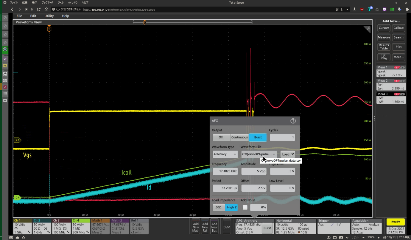
In the dialog in Figure 14, we can confirm that the program set the following parameters, from top-left to bottom-right.
- "Burst" mode selected
- "1" burst selected
- "Arbitrary" waveform selected
- A temporary CSV file selected
- Period of "57.2 µs" selected. (The instrument computes the Frequency of 17.48 kHz.) The 57.2 µs period is based on the sum of:
– 0.1 µs header (OFF)
– 55 µs first pulse width
– 0.5 µs Toff1
– 0.5 µs second pulse width
– 0.5 µs Toff2
– 0.5 µs third pulse width
– 0.1 µs trailer (OFF) - High Level of "5 V" and Low Level of "0 V" selected. (The instrument computes Amplitude of 5 Vpp and Offset of 2.5 V.)
- Load Impedance of "High Z" selected
- No noise added
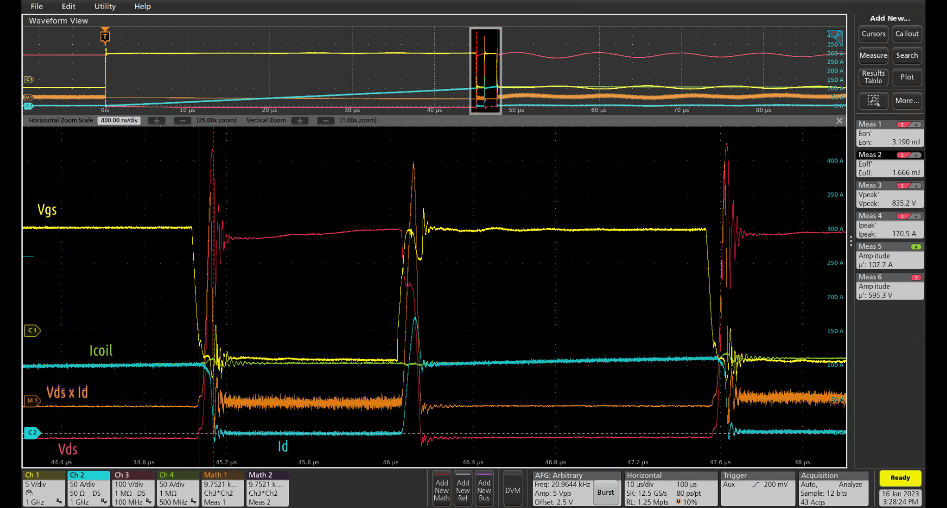
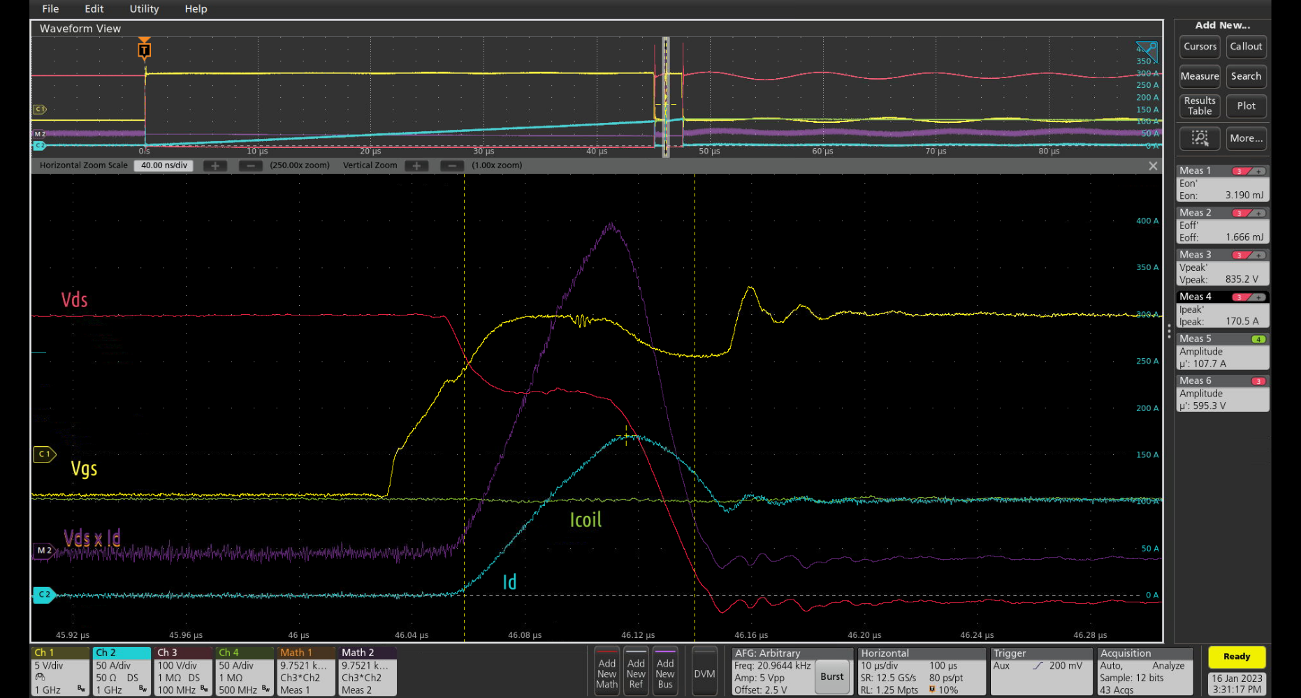
Note that to achieve accurate energy loss measurements, it is important to remove any skew (deskew) between current and voltage probes. This has been performed prior to the test run shown in Figure 15.
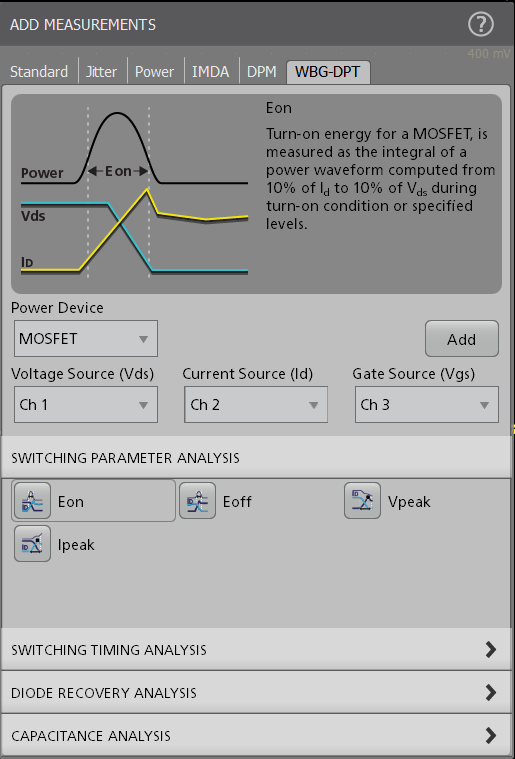
The VDS_peak, ID_peak, EON and EOFF measurements were made using the WBG-DPT double pulse measurement package on the 6 Series MSO. (More on this in the next section.)
Most important, we see that the Qorvo DUT hard-switches a 100 A current at a 1 MHz PWM switching frequency and maintains a clean, square pulse shape.
Automated DPT Measurements
This application note is focused on system setup and gate drive signal generation. Once these the system is configured, the actual switching measurements must be considered. Measurements, like the energy loss measurements shown in Figure 15 may be defined using math on the oscilloscope. However, the measurements shown in Figure 15 were performed using the WBT-DPT double pulse testing software on the 6 Series MSO. This automated DPT testing software package complies with JEDEC and IEC standards for DPT testing on WBG devices like SiC /GaN MOSFETs and on IGBTs.
In addition, Tektronix and Keithley offer stand-alone Arbitrary Function Generators and DC power supplies that can round out a complete solution for double pulse testing.
Summary
As demonstrated in this application note, the internal AFG in the 5 or 6 Series MSO can be used for generating double pulse signals even while the oscilloscope acquires signals. Specially-designed double pulse testing software (WBG-DPT) helps to streamline key measurements. The script described in the application note, and developed by engineers at Qorvo, may be used to generate double pulse gate drive signals using the oscilloscope's internal AFG, providing an effective solution for double-pulse testing. This simplifies double pulse testing and reduces system cost. It also limits the number of ground points. Finally, tests can easily be run with full remote control allowing distance between the engineer and the high-voltage, highcurrent DUT for added safety.
Find more valuable resources at TEK.COM
Copyright © Tektronix. All rights reserved. Tektronix products are covered by U.S. and foreign patents, issued and pending. Information in this publication supersedes that in all previously published material. Specification and price change privileges reserved. TEKTRONIX and TEK are registered trademarks of Tektronix, Inc. All other trade names referenced are the service marks, trademarks or registered trademarks of their respective companies.
02/2023 48W-73984-0