Contact us
Call
Call us at
Available 9 AM - 5 PM CET Business Days
Download
Download Manuals, Datasheets, Software and more:
Feedback
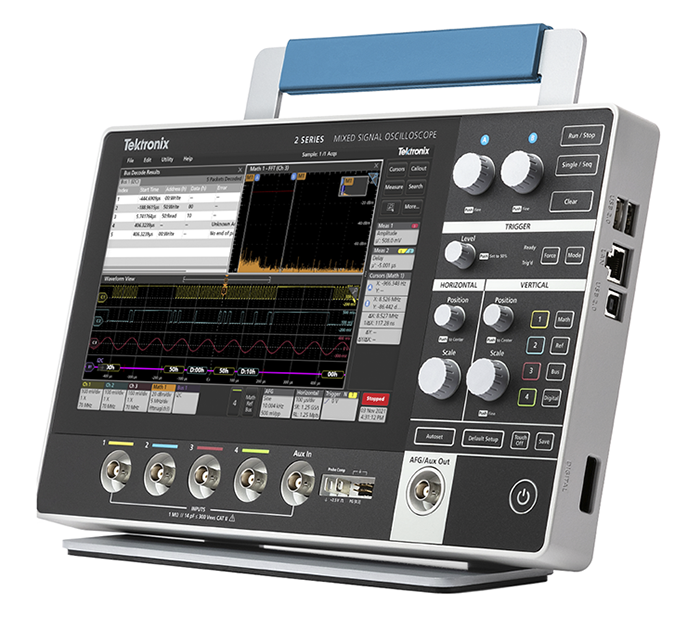
2 Series MSO
Mixed Signal Oscilloscope Datasheet
More Information
- Portable Oscilloscope - 2 Series MSO Mixed Signal
- Product Support
- Explore more Software models