
New De-embedding, Embedding, and Equalization Software for High-Speed Systems Verification and Compliance Test
Verification and compliance of high-speed systems require visibility across the full signal path—from DUT to oscilloscope input. This means de-embedding test fixtures and interconnects, embedding realistic system conditions, and, in some cases, applying receiver equalization to emulate Tx/Rx behavior. Only then can you confirm both compliance and real-world performance.
Tektronix’s new Signal Integrity Modeling (SIM) software — available for the 5 Series B MSO, 6 Series B MSO, and 7 Series DPO oscilloscopes— lets you de-embed, embed, and apply equalization to your signal directly on your oscilloscope.
From multi-gigabit serial designs like PCIe, DDR5, USB4, and multi-lane Ethernet to cutting-edge RF and power electronics, SIM helps ensure your design meets both compliance and real-world performance requirements. By removing and simulating reflections, loss, and delay from cables, components, and fixtures, SIM eliminates two common traps in validation—false failures and false confidence—so results reflect your device, not your setup.
In this blog, we’ll explore how SIM gives you full visibility into the signal path, providing the confidence needed to validate standards compliance and real-world performance for faster time-to-market.
Accurate DUT Visibility Through De-Embedding
Probe loading, cable loss, and fixture reflections are common in high-speed, RF, and fast-switching power designs. Without compensating for these unwanted signal-path effects, you might think your device under test (DUT) is broken or non-compliant when it’s actually fine—leading to false failures. De-embedding is also critical when direct probing is impractical, or when compliance requires visibility at standardized test points (TP0, TP1, TP2, etc.) defined for PCIe, USB, DDR, and others. In these cases, de-embedding allows you to virtually shift the measurement reference plane to the required location.
With SIM software, you can define a variety of models — including S-parameter, transmission line, RLC, transfer function, FIR, and shunt — to correct for loss, reflections, and delay from the setup. SIM also supports cascading multiple models to represent the entire measurement path, giving you full visibility into the DUT’s true signal behavior.
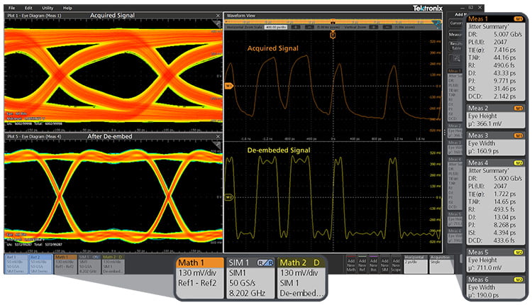
Figure 1. Before and after de-embedding: The simulation defined in “SIM 1” outputs to “Math 2”, which has the measurement artifacts removed, resulting in a cleaner waveform and eye diagram.
See how SIM makes de‑embedding easier, watch this short demo video, De-Embedding PCB Cable and Fixture Effects for Accurate Eye Diagram Measurements with an Oscilloscope.
Embed to Simulate Real-World Effects
Clean preliminary measurements can create false confidence — the device appears fine, but in the real system performance collapses. Impedance discontinuities, channel loss, reflections, and ISI can break the link. Embedding may also be necessary to place the DUT within its required load impedance. That’s why embedding real-world effects is essential not only for compliance but for thorough system testing and validation before deployment.
SIM software allows you to virtually embed real-world interconnects—such as backplanes, cables, or channels. For example, for USB 3.0 compliance testing, SIM can embed PHY and controller interfaces to ensure they conform to the USB 3.0 standard.
You can also apply S-parameter models to simulate various environments directly on your oscilloscope, enabling margin analysis and signal integrity validation without needing to build or swap physical hardware.
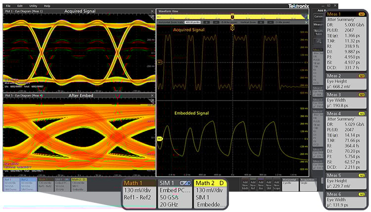
Figure 2. Reduced eye height and width due to ISI from embedding.
Open Closed Eyes and Validate Performance with Equalization
At today’s data rates, channels introduce loss, reflections, and crosstalk that can collapse the signal eye, making timing and amplitude margins hard to measure. Equalization restores that visibility by counteracting distortion in a way that mirrors how real receivers or transmitter operate. The result: cleaner eyes, more accurate jitter and noise measurements, and confidence that your system will meet compliance.
Unlike de-embedding, which removes fixture effects in a fixed way, equalization is adaptive. It adjusts for frequency-dependent behavior and changing channel conditions, allowing you to observe performance as it would actually be recovered in hardware. On the transmit side, techniques such as pre-emphasis or de-emphasis prepare the signal before it enters the channel. On the receive side, methods like CTLE, FFE, and DFE reconstruct the eye to recover integrity at the far end. This dynamic process is essential for standards from PCIe and DDR5 to USB 3.0 and multi-lane Ethernet.
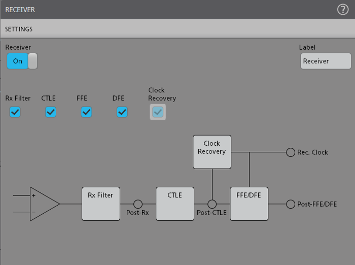
Figure 3. SIM software menu for receiver equalization.
SIM Advanced integrates these capabilities into the oscilloscope, so you can apply transmitter EQ, build custom receiver models, and explore system margins without ever needing direct access to the silicon. Whether your goal is compliance, debug, or design exploration, equalization ensures your measurements reflect how signals behave in the real world.
Fast, Easy, and Flexible
Whether you’re focused on early bring-up, compliance, or debug, SIM software’s modern and intuitive user-interface is designed to make the process easier. With touch-optimized controls and a straightforward interface, you don’t need to be an expert to get started. Simplified workflows and a modernized architecture enable fast setup and processing of de-embed and embed filters, from the simplest to the most complex scenarios.
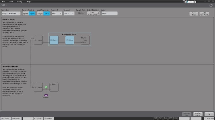
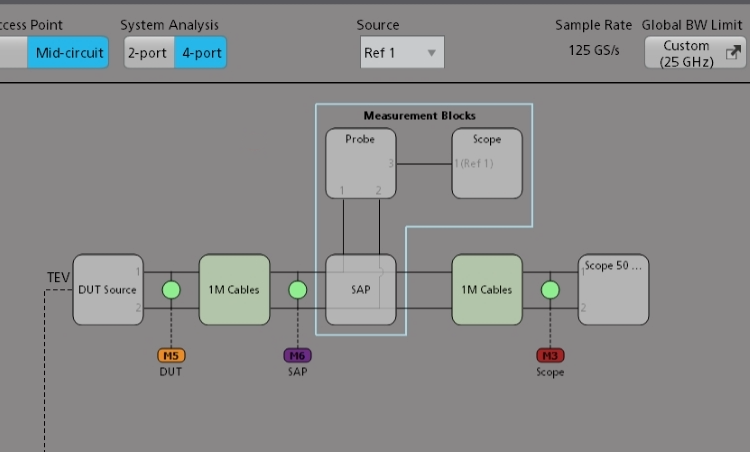
Figure 4. A simple de-embedding example within the SIM menu with the M2 test point resulting in the Math 2 waveform after de-embedding the Physical Model.
Powerful Capabilities Including Unlimited Simulations and Test Points
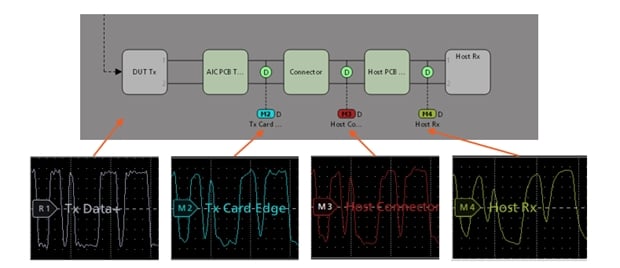
Figure 5. Comprehensive signal path visualization with SIM software.
SIM makes it possible to run essentially an unlimited number of simulations and test points. You can view your signal at any virtual measurement (test point) location to see before-after effects of each block. You can also model parallel paths or more complex signal chains without being limited to just one simulation at a time. Results are preserved side-by-side, so you can compare the original and corrected signals directly and quickly explore “what-if” scenarios.
For example, you can evaluate different CTLE or FFE settings on a PCIe Gen4 link to see which recovers eye margin most effectively. In DDR5 debug, you can compare multiple interposer and DIMM connector combinations before committing to a layout. In USB4 / DisplayPort testing, you can evaluate the impact of alternate cable lengths or via designs without re-running the workflow from scratch.
In each case, SIM reduces iteration time from hours of back-and-forth to minutes of side-by-side insight.
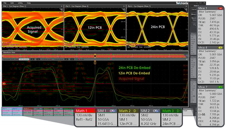
Figure 6. Parallel SIMs allow for fast “what-if” validation. For example, de-embed a 12-in PCB trace, then de-embed a 24-in PCB trace with a second model to evaluate optimal design performance and margin. Original and de-embedded eyes/waveforms shown.
From Clearer Eyes to Deeper Insight: Using SIM and DJA Together
Pairing SIM software with the Tektronix Advanced Jitter Analysis software (opt. DJA) helps understand the signal transmission quality in your high-speed system in greater detail. The Advanced Jitter Analysis software can isolate sources of jitter with TIE, eye diagram, BER bathtub, and spectrum analysis, and decompose total jitter into random jitter, deterministic jitter, and their subcomponents. With these insights you can correlate jitter with likely root causes and use SIM software to de-embed and open eye diagrams.
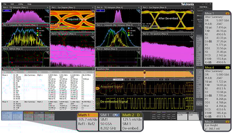
Figure 7. Comparing acquired and de-embedded signals using SIM alongside Tektronix Advanced Jitter Analysis (Opt. DJA).
The Figure above shows how SIM and DJA work together to reveal both physical and statistical improvements in signal quality. The upper left panes show the acquired waveform, while the right panes show the same waveform after SIM de-embedding removes fixture and interconnect effects. The eye diagram opens significantly, and the TIE histogram narrows along the time axis, indicating reduced total jitter and improved timing stability.
This also suggests that while ISI and data-dependent jitter (DDJ) have been largely removed by de-embedding, the remaining jitter is dominated by periodic, deterministic (correlated) components—likely stemming from transmitter PLL phase noise, power-supply coupling, or slow clock modulation. When viewed alongside the TIE spectrum, which shows a lower overall noise floor that slopes downward with frequency, it becomes clear that high-frequency noise has been suppressed and that slow, periodic wander now dominates.
The bathtub plot further confirms these improvements: it widens with steeper edge slopes, demonstrating that bit-error probability decreases and timing margins expand after de-embedding. Together, SIM clarifies the physical signal path, and DJA quantifies how jitter evolves, giving engineers a complete, all-in-one view of signal integrity and root cause.
Get to Market Faster with Signal Integrity Modeling Software
The new Signal Integrity Modeling (opt. SIM) software’s intuitive design and powerful features will help you explore, iterate, and optimize your high-speed systems with speed and precision. Whether you’re working on early bring-up, compliance, or debugging, you can rely on SIM to accelerate decision-making, ensure compliance, and get to market faster than ever.
Learn more about SIM software today.