
THIS APPLICATION NOTE
- Explains how to measure turn-on and turn-off delays when the power supply is controlled by connecting and disconnecting the AC mains input
- Explains how to make turn-on and turn-off timing measurements when the power supply is controlled by a remote on/off signal
- Explains how to make automated timing measurements between many point-of-load regulated supplies
The instrument used in this application note is a 5 Series Mixed Signal Oscilloscope equipped with 8 FlexChannel® inputs. An 8-channel 6 Series B MSO will operate almost identically. Each FlexChannel input can measure one high-resolution analog signal, or by connecting a TLP058 logic probe measure 8 digital logic inputs.
Introduction
In systems that rely on multiple power rails, power-on sequencing and power-off sequencing can be critical. If the power supplies do not turn on and off in the proper order, or if the rise-times of the power supplies are too fast or slow, the system may malfunction or components may be damaged.
The traditional method of evaluating the sequence is to measure the timing between supplies with a 4-channel oscilloscope. When more than 4 signals need to be verified, multiple captures must be taken or two oscilloscopes must be used, usually by triggering on a common power good / fail signal. In both cases the measurements must be synchronized and combined to get a complete picture.
With an 8-channel oscilloscope, power supplies with up to 8 power rails can be characterized using analog probes. To measure turn-on and turn-off timing relationships on power supplies with more than 8 power rails, a mixed signal oscilloscope with digital signal inputs and independently adjustable thresholds may be used.

Turn-on and Turn-off Delays with AC Mains Input
The first example is a 3-phase motor drive that is controlled by connecting and disconnecting the AC mains. After the circuit is powered up, the Run/ Stop signal goes high, and the 3-phase pulse-width-modulated motor drive signals start. The oscilloscope’s window trigger starts the signal capture when either phase of the AC line voltage exceeds ±10V and waveform cursors provide the turn-on delay measurement.
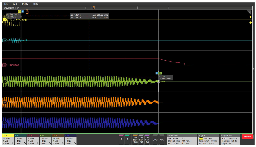
After the AC line voltage is disconnected, the stored energy in the drive allows the motor to continue to run for a short time. In this case, the oscilloscope’s window trigger starts the signal capture when the peaks of the AC line voltage drop by at least 30% for at least 50 ms. Waveform cursors measure the turn-off delay for this unloaded motor to be just over 1 second.
Turn-on and Turn-off Delays with Remote On/Off
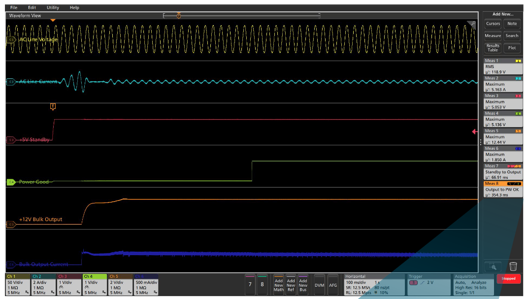
The next example is an off-the-shelf switching power supply that produces a high-current, regulated 12 VDC output. This power supply is remotely controlled with a switch on the front panel of the instrument. Shortly after the switch is pressed, the +5V standby voltage is turned on, enabling the switching converter to start. After the +12V output is in regulation, the Power Good (PW OK) signal goes high to indicate to the load that the supply is reliable.
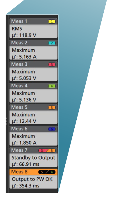
The +5 V standby voltage signal provides a simple rising edge trigger for the acquisition of the relevant signals. Automatic measurements verify that the delay to the output voltage turn-on is <100 ms, and the delay from output voltage turn-on to PW OK is in the specification range of 100 – 500 ms.

After the power supply’s main switch is turned off, the switching converter is turned off and the output voltage decreases. The power supply is specified to remain in regulation for at least 20 ms after the switch is pressed. Most importantly, the PW OK signal is specified to fall 5 – 7 ms before the +12 V output voltage falls out of regulation, allowing the load time to react and shut down cleanly.
The PW OK signal provides a falling edge trigger for the acquisition of the relevant signals. The waveform cursor measurement verifies that the PW OK pre-warning signal is operating as specified.


To verify that the power supply turn-on timing remains within specifications over multiple power cycles, infinite persistence is used to display the signal timing variations and statistics displays of automated timing measurements quantify the variations. In this setup, the 50% point of the +5 V Standby voltage is used as the timing reference. The turn-on sequence is repeated 10 times and the timing variations over the 10 turn-on cycles are within a little over 1%.


Point-of-load Regulated Power Supply Timing
The final example shows the timing of point-of-load supplies in the product during power-up. The input power supplies to the circuit board is the +5V Standby and bulk +12 VDC supply in the previous example.
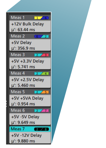
The automated turn-on delay measurements in this test are made between the automatically-calculated 50% points of each of the waveforms, meaning that each measurement has a different configuration with a different set of measurement thresholds. The first measurement shows the delay from the +5V Standby signal to the bulk +12V supply and the second measurement is the delay to the main +5V supply. The remaining measurements are the sequence of critical delays from the main +5V supply.

The automated turn-off delay measurements in this test are made between the points of each of the waveforms that are 5% below their nominal value. Unlike the previous percentage-based measurement thresholds, each measurement has an absolute voltage threshold. As the power supply shuts down, the Power Good signal falls. As you can see in the screen shot, some of the supplies are more heavily loaded and turn off more quickly than others.

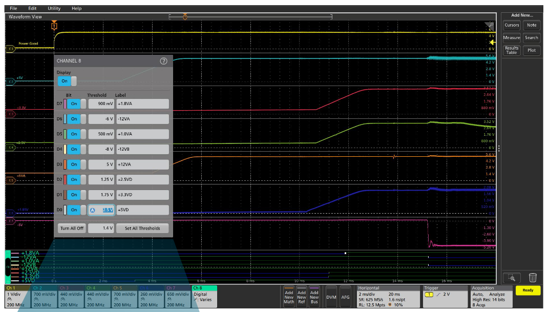
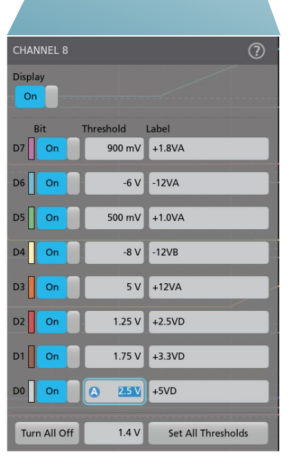
Most power supply designers have had to try to make these timing measurements with a 4-channel oscilloscope. But, even with a 6- or 8-channel oscilloscope, there will be times when a complex system will have more than 6 or 8 power supplies. The FlexChannels® of the 5 and 6 Series MSOs enable timing measurements (but not amplitude measurements) with digital channels. By simply attaching a TLP058 8-channel logic probe to a FlexChannel, you gain access to eight digital inputs.
Automated timing delay measurements are simply based on the times at which the signals cross their respective threshold voltages. Since each automated measurement configuration can include a unique threshold value (typically 50% of the signal amplitude) and each digital channel can have a unique threshold value (also typically set to 50% of the power supply voltage), 5 or 6 Series MSOs with logic probes can make power supply timing delay measurements on up to 64 channels.
Power Supply Rise-Time Measurements
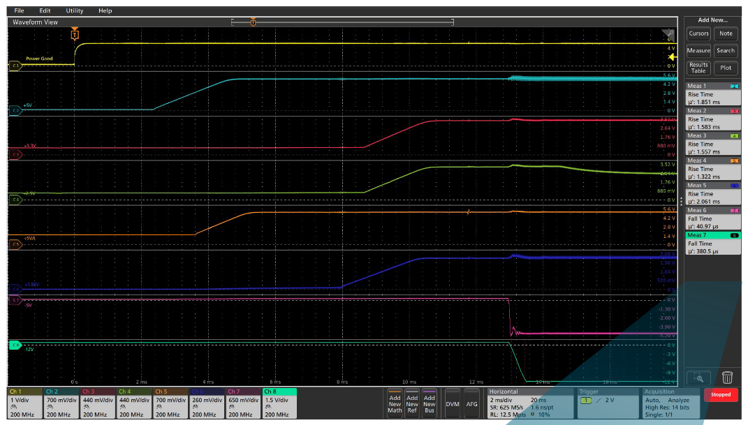
In addition to the power supply sequencing, the rise-times of power supplies must be controlled to meet the specifications of some critical components in a system.
Automated rise- and fall-time measurements are also made based on voltage reference points which are, by default, automatically calculated to be 10% and 90% of the signal amplitude of each channel. In this simple example, the rise-times of the positive supplies and the fall-times of the negative supplies are shown in the measurement badges at the right side of the display.
