Contact us
Call us at
Available 6:00 AM – 5:00 PM (PST) Business Days
Download
Download Manuals, Datasheets, Software and more:
Feedback
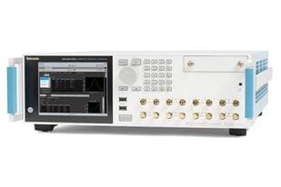
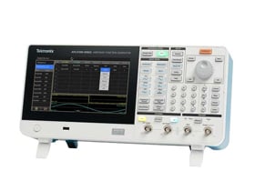
Arbitrary Waveform Generators
The Tektronix arbitrary waveform generator family provides industry-leading performance with sample rates up to 50 GS/s, up to 8 channels, and intuitive software packages that simplify the creation of complex signals. The unparalleled flexibility, speed, and fidelity of the Tektronix arbitrary waveform generators make them an ideal solution for high-speed serial, optical communications, radar test, and electronic warfare.
Find the Best Waveform Generator for Your Bench

Waveform Generator Software
Tektronix offers a suite of powerful software tools designed to simplify waveform creation, signal editing, and instrument control. These tools help engineers accelerate test setup, improve flexibility, and enhance overall productivity.
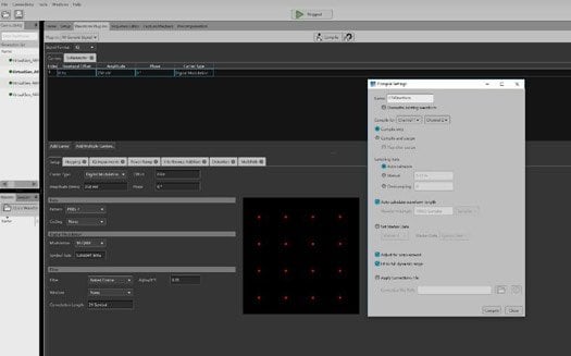
SourceXpress®
A PC-based software platform that mirrors the user interface of Tektronix AWG70000 and AWG5200 Series generators. SourceXpress enables users to create, edit, and manage waveforms remotely—freeing up bench instruments for testing and streamlining workflows in multi-user environments.
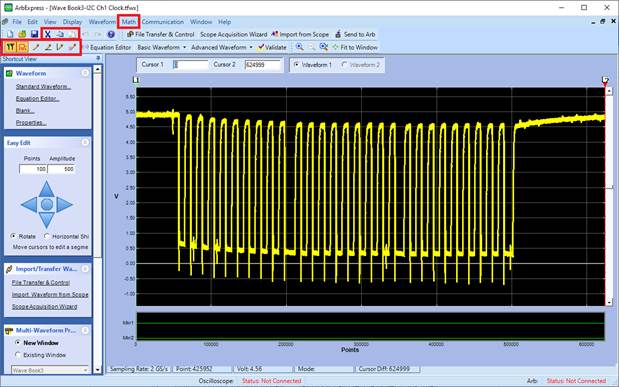
ArbExpress®
An intuitive waveform creation and editing tool that allows you to design complex signals quickly and easily. ArbExpress supports importing waveform data from Tektronix oscilloscopes and converting it into formats compatible with AWG/AFG instruments, enabling a seamless capture-and-generate workflow.
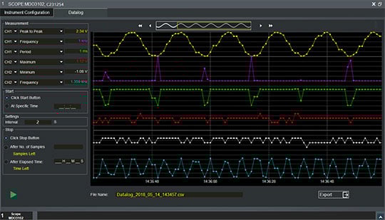
TekBench™
Ideal for lab environments and student use, TekBench simplifies the control of Tektronix arbitrary function generators and oscilloscopes. With features like automated measurement logging and frequency response testing, TekBench is a perfect tool for efficient experiment execution.
Explore Related Signal Generator Options
Key features of Tektronix waveform generators
Tektronix arbitrary waveform generators offer the complete solution for generating complex RF signals and simulating real-world environments in a single instrument. With a Tektronix arbitrary waveform generator, you can:
- Synchronize multiple units to achieve a multi-channel, high-speed AWG system
- Quickly select, edit, and play waveforms and trigger on events directly from the AWG front panel
- Simulate real-world environments by playing back, editing, or re-sampling captured signals from an oscilloscope or real-time spectrum analyzer
- Import waveform vectors from third-party tools such as MATLAB
Arbitrary Waveform Generator Applications
- Communications: Simulate real-world signals to test and validate communication systems, ensuring reliability and performance under different conditions.
- Semiconductor Testing: Generate precise electronic signals to evaluate semiconductor components, aiding in the development and quality assurance of integrated circuits.
- Medical Devices: Create complex biological waveforms to test medical equipment, ensuring devices operate safely and effectively in clinical environments.
- Automotive Electronics: Simulate sensor signals and communication protocols to validate automotive electronic systems, enhancing vehicle safety and functionality.
Benefits of Tektronix Waveform Generators
Tektronix AWGs are engineered for precision and performance, offering an unmatched combination of hardware capability and software control.
- High Signal Fidelity: Achieve low-jitter, high-resolution signal generation with leading-edge vertical resolution and sample rates, enabling the most accurate simulation of real-world signals.
- Multi-Channel Synchronization: Easily generate synchronized waveforms across multiple channels for complex, time-aligned testing of multi-signal systems.
- Deep Waveform Memory: Store and play back long or complex waveform sequences without sacrificing performance—ideal for simulating full protocol patterns or stress conditions.
- Intuitive User Experience: With SourceXpress and ArbExpress, waveform generation is easier than ever. Users can build, preview, and deploy signals with drag-and-drop interfaces, real-time previews, and remote access options.
Conquering Radar Signal Generation with an Arbitrary Waveform Generator

Creating complex radar signals can be a challenging endeavor. Learn how to make the process more efficient in this 25-minute video. The presentation will cover methods for reducing the complexity of writing and debugging your own signal generation code and common traps to avoid when generating complex signals.
Explore Resources Related to Waveform Generators
25 things you can do with a function generator

The signal generator pairs with an acquisition instrument such as an oscilloscope or spectrum analyzer to create a complete measurement solution
Using an Arbitrary Waveform Generator for Threat Generation

For complex threat generation used in radar system evaluation; a high sample-rate arbitrary waveform generator like the AWG70000 series is a great source to consider.
Using a Waveform Generator for Direct RF Complex Signal Generation

By considering the properties of the signal you wish to generate and the AWG’s performance, direct RF signal generation in the 1st or higher order Nyquist bands is possible using RF DAC’s with complex modulator.
How to Select the Right Waveform Generator
Selecting the right waveform generator means matching its key specifications to your application. Focus on these five critical areas to make an informed choice:
- Frequency Range and Sample Rate: Ensure the generator supports the frequency range of your application. Ensure the sample rate is at least 2-5 times higher than your signal's highest frequency component to accurately reproduce complex waveforms.
- Vertical Resolution: Choose a higher resolution (e.g., 16-bit) for greater amplitude accuracy and lower noise, which is critical when testing sensitive analog or RF devices.
- Waveform Memory: Deep memory is essential for generating long, complex, or non-repeating signals, such as full communication protocols, sensor emulation, or stress testing. More memory allows for higher resolution over longer durations without compromising signal integrity.
- Number of Channels: Select a multi-channel generator with tight synchronization for complex tasks like I/Q signal generation, multi-lane bus testing, or phase-aligned signals.
- Advanced Features and Modulation Support:
For applications requiring custom or real-world signal emulation, look for advanced features such as:
- Arbitrary waveform creation
- Sequencing and waveform hopping
- Built-in modulation (e.g., AM, FM, PM, FSK, PWM, IQ)
Matching the right sample rate, resolution, and memory to your application can be complex. Our experts can help you select the perfect waveform generator with confidence.
Waveform Generator FAQs
What is a waveform generator?
A waveform generator is a piece of electronic test equipment used to generate a variety of electrical signals. These signals act as a stimulus to a device under test (DUT), allowing engineers to verify a circuit's performance, troubleshoot issues, or simulate real-world conditions. The types of signals can range from simple, standard waveforms to complex, user-defined patterns.
What is the difference between a waveform generator and an arbitrary waveform generator (AWG)?
A waveform generator is a general term that refers to any instrument capable of producing electrical waveforms. This includes both function generators (also known as AFGs—Arbitrary Function Generators) and arbitrary waveform generators (AWGs). The key difference lies in waveform flexibility and complexity:
Function Generators / AFGs typically produce standard waveforms such as sine, square, triangle, and pulse. Some may offer limited arbitrary waveform capabilities, but they are generally optimized for ease of use and basic signal generation.
Arbitrary Waveform Generators (AWGs) are more advanced instruments designed to generate highly complex, user-defined waveforms with precise control over timing, amplitude, and shape. They are ideal for simulating real-world signals, such as sensor outputs, communication protocols, or distorted waveforms used in stress testing.
What is a waveform generator used for?
A waveform generator is a classification of a signal generator used to generate electrical waveforms over a wide range of signals. Common types of waveforms outputs include sine wave, square wave, ramp or triangular wave, pulse wave, cardiac pattern wave, gaussian pulse waves, arbitrary waves. These waveforms can be injected into a test circuit and analyzed to confirm the device is operating properly.
How do you use a waveform generator?
Arbitrary waveform generators are very user-friendly and can be used to test a circuit’s design in just a few steps.
- Enable the output control.
- Choose the desired waveform type, such as wine wave, square wave or arbitrary wave.
- Connect the waveform generator to an oscilloscope to visualize and capture your signal.
- Configure the desired frequency and amplitude.
- Attach the output leads to your device under test.
What’s the difference between a function generator and a waveform generator?
A function generator has a preset list of waveforms or patterns that it can play. The operator can change the parameters of a waveform, such as how fast it’s played, the amplitude and offset, or add basic distortion or modulation.
An arbitrary waveform generator is a more complex instrument that can produce almost any waveform you can imagine. Arbitrary waveform generators are essentially sophisticated playback systems that deliver waveforms based on stored digital data that describes the constantly changing voltage levels of an AC signal. These instruments are typically used to produce custom compiled waveforms—rather than pre-set common waveforms.
What are the types of signal generators?
There are many types of signal generators, including function generators, arbitrary waveform generators, and vector signal generators. To clarify terminology used in this space and see the differences between each type of signal generator, view the chart below.
| Signal Generator | Generic category name for analog and digital electronic signal sources. |
| Function Generator | Signal generators are typically used when common waveforms like sine, wave, triangular, etc. are needed. |
| Arbitrary Function Generator | Function generators are capable of arbitrary compiled waveforms. |
| Arbitrary Waveform Generator | Arbitrary waveform generators are mostly used when custom compiled waveforms (rather than preset common waveforms) are needed. |
| RF Signal Generator | RF signal generators are used for wireless applications and typically provide normal analog modulation such as AM, FM, and PM as well. |
| (RF) Vector Signal Generator | RF vector signal generators support both analog and vector modulation on RF carriers for digital communication applications. |