Contact us
Call us at
Available 6:00 AM – 5:00 PM (PST) Business Days
Download
Download Manuals, Datasheets, Software and more:
Feedback

Today’s efficient power converters demand less input power per watt of output, but they also demand more in terms of power supply measurements. Topologies are increasingly complex, and parasitics are everywhere, demanding careful comparison of simulations and measurements. Increasing switching frequencies make it harder to control EMI. And systems require a wide range of low-noise, fast-responding power supplies (like DC power supplies). You've come to the right place.
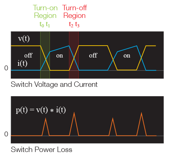
Switching Loss Measurement and Analysis
Switching loss makes up a significant percentage of the total loss in a switch mode power supply. Learn how to measure it under operating conditions.
- Define switching loss during turn-on, conduction, and turn-off
- How to set up measurements
- Performing switch loss using manual setup and math
- Performing switch loss using automated power analysis options
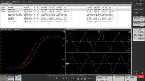
In-circuit Inductor and Transformer Loss Measurement
Find out about making in-circuit oscilloscope measurements on magnetic components, including inductance, loss and B-H curves.
- Brush up on practical magnetics
- Inductance measurements under operating conditions
- Measure loss in inductors and transformers
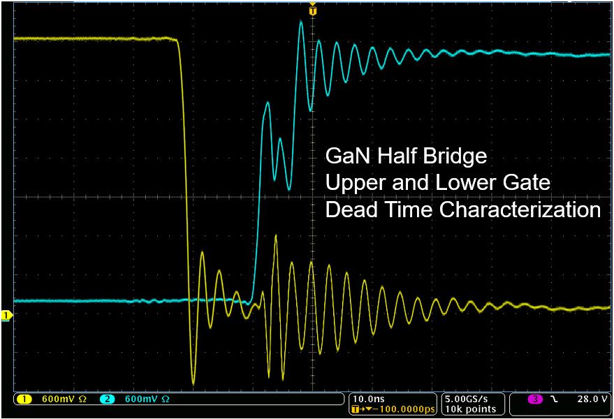
GaN and SiC Switching Device Measurements
High switching speeds and common mode voltage present measurement challenges. Learn how to address them.
- Overcome high common mode voltages
- Simultaneously measure multiple control and timing signals
- Achieve faster automated measurements
- Conduct pre-compliance EMC checks
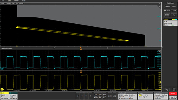
Transistor Safe Operating Area (SOA)
Use measurements to confirm that FETs, IGBTs, or BJTs are operating within the safe operating area specified in their datasheets.
- Making spot checks on voltage and current
- Using limit test to look for overcurrent or overvoltage
- Automated mask testing
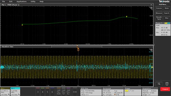
Power Supply Rejection Ratio
Power supply ripple rejection ratio (PSRR) is a measure of how well a Power Converter AC-DC or DC-DC circuit rejects ripple from reaching its output. This is typically performed at various frequencies and is very critical qualifier for the AC-DC or DC-DC converters. Tektronix new PWR software for the 5 and 6 Series MSO now enables this measurement on using the same oscilloscope so you don’t need a different test set-up.
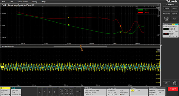
Power supply control loop response measurements
Control loop analysis is an important step in checking for proper frequency response in your control logic. You need to check for loop frequency response and measure the gain and phase margin of the circuit to get insights to the stability of the system. You can avoid using a VNA for Bode plot measurements by using an oscilloscope with built-in function generator. Learn more about control loop analysis using the links below.
