Download

Download Manuals, Datasheets, Software and more:

DOWNLOAD TYPE
MODEL or KEYWORD

Feedback

Digital Power Management and Analysis Software - Enabling Power Integrity Analysis

5 Series B/6 Series B MSO Option 5-DPMBAS, 5-DPM, and 6-DPM Application Datasheet

5 Series B/6 Series B MSO Option 5-DPMBAS, 5-DPM, and 6-DPM Application Datasheet

Most of today’s electronic designs require different supply voltages to function properly. Some components within a given circuit require multiple voltage levels. Testing a product for its specification is a time consuming process; debugging is even more cumbersome process. Hence, power integrity has started playing a significant role and the companies are able to improve their time to market.

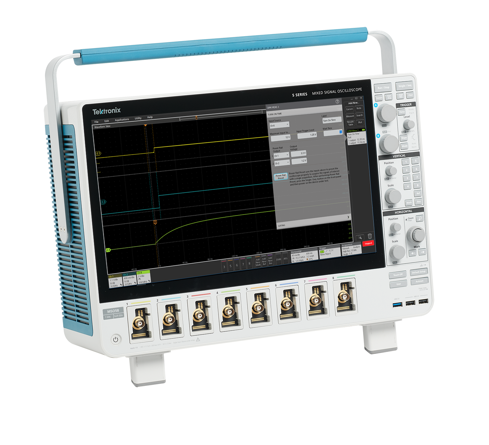
The Digital Power Management and Analysis (DPM) software option provides automated power rail measurements for the Power Integrity Analysis on the 5 Series B/6 Series B MSO. The solution enables simultaneous analysis of multiple power rails using power rail probes and sequencing of measurements using passive probes. The solution is designed with the user work flow in mind to help design engineers meet their time-to-market needs. It also generates an automated report that includes measurements, test results, and plot images.

The solution in combination with the Tektronix 5 Series B/6 Series B MSO and Power Rail Probes helps engineers to measure and analyze Ripple, Transient characteristics, Power Supply Sequencing, Amplitude, Jitter, Eye and timing diagrams and perform measurements repeatability, analyse results to increase accuracy. The multiple FlexChannel® inputs and the next generation user interface of the 5 Series B/6 Series B MSO enables engineers to view the waveform (time-domain), a spectral view (frequency domain), or both simultaneously to efficiently debug and analyze the circuit design.

Salient Features of the software solution

  • Test up to 7 rails simultaneously with automated measurements and configure each channel
  • Allows you to identify the source of the ripple
  • Analyze high frequency ripple overlaid on ripple for better design – Ripple on Ripple
  • PSIJ measurement identifies the inter-dependency between high speed serial load and power rail noise
  • Single click detection and set up of probes
  • Auto-zero: User can deskew probes from menu for each channel

Customer applications

Power integrity analysis plays a critical role especially with highly-integrated system on chip and microprocessor designs in which multiple technologies interface together. It is important to look at each DC line to see if the power supplied is within the tolerance band of a target system or device. The typical applications can be found across industries that need power conversion and have multiple DC voltage levels in the circuit design. Some examples include:

  • Mobiles, Computers, and Tablets

  • Automotive

  • Industrial

Measurement overview

Two of the most important measurements while analyzing a Power Supply design are Ripple and Transient. However, when looking at the complex IC designs these days, there are a few other measurements like Power Sequencing and Jitter that have also become important.

Ripple analysis

In simple terms, Ripple is defined as the residual AC voltage on a constant DC component (offset). Typically, the ripple component is often small in magnitude relative to the DC component.

DPM EN US 61W 61560 03

Designers should not confuse Ripple with the System noise. It is possible to see only the ripple by minimizing oscilloscope and probe noise when measuring DC power rails.

The Digital Power Management solution enables the analysis of multiple power rails simultaneously to reduce test times during design and validation. The 8-channel 5 Series B/6 Series B MSO can measure up to 7 power rails at once.

The solution also leverages the Spectrum View capability to perform Spectrum Analysis on the ripple. This helps the designers to identify the source of ripple and help to save a lot of time and effort on debugging.

DPM EN US 61W 61560 03

Analyze cycle-by-cycle by selecting a PWM clock (if available) and view peak-peak and RMS values for each ripple cycle. This gives statistics for all of the cycles within an acquisition. Bandwidth limit capability enables designers to analyze the ripple numbers at different bandwidths.

DPM EN US 61W 61560 03

One of the unique features of the DPM solution is the ability to leverage the capabilities of the Power Rail probes to analyze additional high frequency noise overlaid on the ripple. This is typically known as Ripple-on-Ripple.

Power sequence analysis

Power sequence analysis enables power designers to ensure that the power rails reach the on or off states within the expected times.

Power sequence analysis runs simultaneously on up to seven power rails. Configure the eighth source as a reference input to measure the turn-on and turn-off time. This enables the designers to measure the power sequencing of their power rails and ensure they reach their turn-on and turn-off states within the required times. Automating these tests helps achieve consistent and accurate results under different load conditions.

DPM EN US 61W 61560 03

To set up the test, configure the nominal input and output voltages, trigger level, and wait time (duration). Pressing the Power Rail Preset button initiates an optimization process in which the software optimizes scale settings, record length, and sample rate for the best results. Turn-on and turn-off times are displayed in the results badge and indicated on the waveform with colors. Results are also available in a tabular format. Compare and validate the design for wait times by observing the results table for anomalies.

Transient analysis

A transient phenomenon in a system is caused by a change of the operating conditions or the system configuration. The importance of transient analysis is to identify the effects the disturbances have on the system performance or the failures they cause to power equipment.

Transient analysis typically includes overshoot and undershoot measurements. Just like Ripple, the application allows for simultaneous automated measurements with a few simple steps. A reference voltage is entered for each power rail before initiating the test. The overshoot measurement gives the difference between the maximum voltage and the reference voltage. The undershoot measurement gives the difference between the minimum voltage and the reference voltage.

DPM EN US 61W 61560 03

Perform this measurement for a single cycle within an acquisition or over every cycle within an acquisition (Cycle Mode). Synchronize cycles based on a power rail signal or another signal in the system. Cycle-by-cycle measurements are analyzed using statistics, histograms, or plots. Bandwidth limit capability enables designers to analyze the ripple numbers at different bandwidths.

Jitter analysis

Jitter measurements help to validate the jitter tolerances on the high-speed side, which uses the DPM outputs to power-on their loads. The common noise sources are crosstalk from data signals, coupling from clocks and power supply switching noise (and harmonics) and SSN (Simultaneous Switching Noise). The DPM multi-rail outputs power on different loads such as FPGA, system/CPU clocks, DDR memories, transceivers, etc. Both, Power Integrity (PI) and Signal Integrity (SI) functions are interrelated and it is important to know that the PI modifications will improve the SI. Power artifacts impact high speed loads. It is important to understand that the power supply noise results in high speed jitter, which eventually results in bit errors, and one can observe the eye closure.

DPM EN US 61W 61560 03

For instance, a SI (Signal Integrity) engineer can measure POL (Point of Load) powering the clock and observe the eye diagram where it is clean and opens up. If the eye diagram is not clean and if there are spurs from POL, then the PI (Power Integrity) engineer can work to modify their power supply design to get better sensitivity. This makes SI engineer see the improvement on the HSS load.

To set up the test, specify the jitter frequency, reference levels, and clock recovery. The Jitter Analysis is included with 5/6-DPM only and is not supported on the 5-DPM-BAS package.

PSIJ analysis

The PSIJ (Power Supply Induced Jitter) measurement acts as a tool that gives insights and confidence to the High Speed Serial (HSS) design engineers to improve the designs before making any power related (hardware) changes during the prototyping phase.

This measurement has two goals:

  • To identify the jitter caused by the power rail noise
  • To suppress the jitter on HSS waveform and see the improvement in the signal quality

The PSIJ measurement correlates periodic jitter (PJ) component in high speed signals (victim) with the power supply (aggressor) rail noise using the jitter suppression technique. The jitter suppression algorithm filters out the specified frequencies from the victim signal which were induced from the power rail source. The HSS designer can configure the notch filter settings with the required center frequency that needs to be removed. It is recommended to run the PSIJ measurement with a constant clock recovery method. The spectrum plots of the HSS before and after filtering out the power rail noise helps to validate the improvement in signal quality. This can also be verified by adding eye diagram plot on the HSS signals.

The measurement gives out essential results such as eye height, eye width, PJ, and TIE before and after filtering.

DPM EN US 61W 61560 03
The image shows a multi-rail example of the effect of noise with various points of loads (POL) such as DDR memory, PCIe, etc.

DPM EN US 61W 61560 03
The image shows improvement in PSIJ results after removing the jitter which was added by the power rail source

Report generation

The application allows for data collection, archiving, and documentation necessary for the design and development process. The DPM software provides the ability to compile all the results of a test run into different report formats (MHT or PDF) with pass/fail results for easy analysis.

DPM EN US 61W 61560 03

Specifications

Ripple analysis
Based on the oscilloscope and the power rail probes used, the ripple varies:
  • <10 mV (MSO6x)
  • >10 mV (MSO5x)
Spectrum View enables to identify the source of ripple
Set bandwidth limit from the measurements
Configure ripple frequency for each power rail
Transient analysis
Measurements include Overshoot, Turn on Undershoot, and DC Rail Voltage
Allows designers to enter voltage levels and reference voltage levels for calculating overshoot and undershoot
Set bandwidth limit from the measurements
Power sequence analysis
Turn on and Turn off times testing enables designers to find out the Turn on or Turn off times of all rails in one go
Allows designers to configure the capture time
Jitter analysis (available on 5/6-DPM only)
Measurements include TIE, RJ, DJ, PJ, Eye High, Eye Low, Eye Height, and Eye Width
Capture jitter across multiple rails at one go
PI/SI analysis
PSIJ measurement to identify the periodic jitter introduced on the high speed serial data due to the power rail noise
Plots
Eye diagram, Spectrum, and Histogram
Report
MHT and PDF format
Raw data can be exported to CSV format
Degauss / Deskew (static)
Automatic detection of probes
Auto Zero: allows to deskew probes from the menu of each channel
Manually deskew from the menus for each channel
Source support
Live analog signals, reference waveforms, and math waveforms

Ordering information

Models

ProductOptionsSupported instrumentsBandwidth available
New instrument 5-DPMBAS (Jitter package not included)5 Series B MSO (MSO54B, MSO56B, MSO58B)
  • 350 MHz
  • 500 MHz
  • 1 GHz
  • 2 GHz
5-DPM5 Series B MSO (MSO54B, MSO56B, MSO58B)
5 Series MSO Low Profile (MSO58LP)
6-DPM6 Series B MSO (MSO64B, MSO66B, MSO68B)
  • 1 GHz
  • 2.5 GHz
  • 4 GHz
  • 6 GHz
  • 8 GHz
  • 10 GHz
Upgrade software on an existing instrument SUP5-DPMBAS (Jitter package not included)5 Series MSO (MSO54, MSO56, MSO58)
  • 350 MHz
  • 500 MHz
  • 1 GHz
  • 2 GHz
5 Series B MSO (MSO54B, MSO56B, MSO58B)
SUP5-DPM5 Series MSO (MSO54, MSO56, MSO58)
5 Series B MSO (MSO54B, MSO56B, MSO58B)
5 Series MSO Low Profile (MSO58LP)
SUP6-DPM6 Series MSO (MSO64)
  • 1 GHz
  • 2.5 GHz
  • 4 GHz
  • 6 GHz
  • 8 GHz
  • 10 GHz
6 Series B MSO (MSO64B, MSO66B, MSO68B)

Software bundles

Bundle optionsDescriptionSupported instruments
5-PRO-POWER-1Y1 Year License Pro Power Bundle5 Series B MSO
5-PRO-POWER-PERPerpetual License Pro Power Bundle
5-ULTIMATE-1Y1 Year License Ultimate Bundle
5-ULTIMATE-PERPerpetual License Ultimate Bundle
6-PRO-POWER-1Y1 Year License Pro Power Bundle6 Series B MSO
6-PRO-POWER-PERPerpetual License Pro Power Bundle
6-ULTIMATE-1Y1 Year License Ultimate Bundle
6-ULTIMATE-PERPerpetual License Ultimate Bundle

Recommended probes

Probe type Nomenclature Probe bandwidth
Power Rail Probes TPR1000 1 GHz Probe
TPR4000 4 GHz Probe

Note:

  • TPR1000 and TPR4000 are the recommended probes for the DPM measurement. The TPR1000 and TPR4000 probes and oscilloscope provides a low-noise measurement solution. The higher input impedance in the probes minimizes the oscilloscope loading effect on the DC rails (50 kΩ at DC).
  • Do not confuse the noise of the oscilloscope and probe with the noise and ripple of the measured DC supply.
  • P6150 and Direct SMA cable with DC Block can also be used for power rail measurement.