
Contact us
Call us at
Available 9 AM - 5 PM CET Business Days
Download
Download Manuals, Datasheets, Software and more:
Feedback
Debugging ECUs with Automated Decode & Trigger
What is the CAN bus?
The Controller Area Network (CAN) is a bus structure originally developed for automotive applications, though it has since been widely adopted across various industries. The CAN bus typically uses a balanced (differential) two-wire interface, which can run over different types of cables depending on the application. The original CAN standard supports data rates up to 1 Mb/s. To address the need for higher bandwidth and improved efficiency, CAN FD (Flexible Data rate) was introduced, allowing transmission speeds up to 10 Mb/s and increasing the maximum data field length for larger payloads. Most recently, CAN-XL has been developed to meet the demands of future automotive and industrial networks, offering data rates up to 20 Mb/s and even larger payload capacities, while maintaining backward compatibility at the physical and protocol layers. Regardless of the version, proper signal integrity is ensured by placing 120Ω termination resistors at both ends of the bus to match impedance.
Since its introduction in the 1980s, CAN technology has been a key enabler of reliable data exchange between electronic control units (ECUs) and vehicle sensors.
CAN bus in the connected car
The amount of data, generated, transmitted, and received in automobiles has increased significantly in recent years, and will continue to rise in the future. Today, many automobiles contain more than 80 Electronic Control Units (ECUs), which are connected via different bus networks. In the years to come, we expect this number to exceed 100 as some luxury cars are already using 150 ECUs.
Greater integration between vehicle subsystems means that, in addition to handling sensor and actuator signals, many ECUs communicate over more serial buses at a time. For example, it is very common for an ECU to communicate over both CAN (for critical systems) and LIN (for lower-priority controls, such as windows and mirrors).
Troubleshooting with a CAN bus decoder and other tools
Because the safety of the driver relies on these systems communicating properly, it’s essential to ensure a CAN bus is configured properly. Fortunately, CAN bus decoding and troubleshooting CAN bus issues is easy when you have the right CAN bus decoding tools, such as a mixed signal oscilloscope. In this short guide, we’ll cover troubleshooting tips and the instruments you need to accomplish the task quickly.
Watch: CAN Bus Decoding and Triggering in Action
This video covers the basics of CAN bus decoding on Tektronix oscilloscopes as well as the setups for decoding, triggering and searching for specific values or conditions.

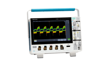
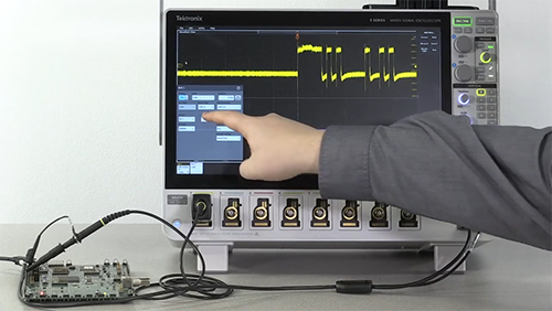
CAN Bus Decoding, Triggering and Searching
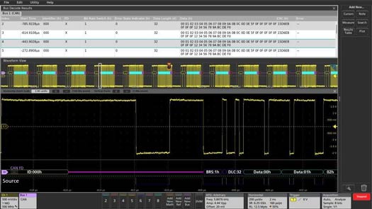
CAN FD signal on Channel 1 being decoded and displayed as a bus waveform (bottom) and event table (top).
Debug the decoded CAN bus protocol
Decoding serial bus protocols manually is time-consuming work, and it is easy to make mistakes. Tektronix’s automotive bus decoding and triggering packages provide straightforward, automated decoding and triggering for popular ECU buses like CAN, CAN FD, LIN and FlexRay.
Troubleshooting Signal Faults
CAN bus protocol decoding is just the beginning. Troubleshooting problems when a bus doesn’t work, or worse, works intermittently, goes beyond the bus traffic and into the realm of signal integrity.
Often these problems, emanating from signal integrity issues in the physical layer like crosstalk, noise, and improper termination, are most effectively detected through waveform analysis.
An oscilloscope allows the engineer to examine the analog bus waveforms to evaluate signal quality and noise, as well as study multiple signals to look for interactions and identify crosstalk.
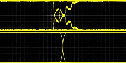
The CAN bus requires 120 Ω termination. An unterminated bus will result in poor signal quality (upper signal).
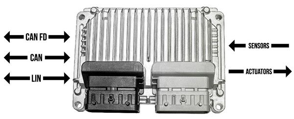
ECUs communicate via CAN, LIN, and other buses, and directly with sensors and actuators.
Visualizing Multiple Channels/Sensors/Actuators
With the complexity of the multi-bus and multi-sensor/actuator systems it’s often difficult to get an overview of the working environment.
Most of Tektronix’s scopes allow the user to view multiple buses and control signals simultaneously. Mixed signal oscilloscopes enable the use of digital channels for bus decoding, freeing up analog channels for evaluating signal quality. The 5 Series MSO is especially good at providing visibility into complex ECUs, thanks to its high channel-count, FlexChannel inputs, and large HD display.
Real-World Applications of CAN Bus Decoder
Tektronix CAN bus decoder are trusted by engineers across the automotive, embedded systems, and compliance testing industries to diagnose and resolve communication issues with speed and precision.
Diagnosing Automotive Network Issues
From engine control to ADAS, reliable communication between Electronic Control Units (ECUs) is critical. Tektronix oscilloscopes with built-in CAN bus decoding allow engineers to:
- Visualize digital waveforms alongside decoded protocol data
- Identify bus errors, arbitration conflicts, and signal integrity problems
- Verify correct message timing (latency) and transmission across vehicle networks or from other ECU inputs/outputs.
This streamlined analysis helps teams uncover the root cause of communication issues faster and ensure consistent performance under real-world driving conditions.
Debugging Embedded System Designs
In embedded designs that incorporate multiple serial protocols—such as CAN, LIN, and FlexRay—visibility across interfaces is essential. With Tektronix mixed signal oscilloscopes, engineers can:
- Decode multiple buses simultaneously
- Correlate analog signal behavior with protocol-level data
- Troubleshoot timing and logic errors across multi-chip interfaces
This synchronized view helps reduce debugging time and improves design validation efficiency.
Identifying Electromagnetic Interference (EMI) Issues
In dense electronic environments, electromagnetic noise can compromise CAN bus communication. Tektronix decoding tools enable teams to:
- Detect EMI-induced anomalies in the waveform
- Correlate protocol-level errors with physical signal disturbances
- Validate system performance under load and environmental noise
This makes it easier to isolate interference sources and verify system compliance with EMC standards.
Step-by-Step Guide to Decoding CAN Bus with a Tektronix Oscilloscope
- Connect the Oscilloscope: Attach the oscilloscope probes to the CAN_H and CAN_L lines. For optimal signal integrity and noise immunity, using differential probes is recommended.
- Configure the Oscilloscope Settings:
- Add CAN bus to a Channel: Tap the Math Ref Bus badge, then Add New Bus button in the Settings bar to launch the BUS1 Settings. Verify the Source is set to the same channel as the oscilloscope connections.
- Set the Voltage Threshold: Double tap threshold to adjust it to accurately interpret the CAN signal levels (typically 3V).
- Choose the CAN Standard: Specify the appropriate CAN protocol (e.g., CAN 2.0, CAN FD, or CAN XL).
- Select the Bit Rate(s): Enter the nominal and, if applicable, data phase bit rates for the CAN bus. These values can be manually set as well.
- Define the Sample Point: Set the sample point as a percentage of the bit time to ensure accurate data sampling (typically 75%).
- Enable Bus Decoding:
- Press the 'Bus' button on the oscilloscope's front panel to define the input as a CAN bus.
- Configure the bus parameters based on the CAN protocol in use.
- Interpret the Decoded Data:
- Graphical Display: The oscilloscope will present color-coded segments representing different elements of the CAN message, such as:
- Start of Frame (SOF): Indicated by a vertical green bar.
- Identifiers: Shown in yellow boxes, displaying either standard or extended IDs.
- Data Fields: Displayed in cyan boxes, representing the transmitted data bytes.
- Cyclic Redundancy Check (CRC): Presented in purple boxes, ensuring data integrity.
- End of Frame (EOF): Marked by a red box.
- Results Table: For a detailed, time-stamped view, utilize the results table to correlate bus activity with specific time instances, facilitating efficient debugging.
- Set Up Triggering (Optional): To isolate specific events or errors, configure the oscilloscope's triggering options based on CAN identifiers, data values, or error conditions. This allows for capturing relevant data frames for in-depth analysis.

Frequently Asked Questions
What is a CAN bus decoder?
A CAN bus decoder is a device that can interpret the signals sent over a Controller Area Network (CAN) bus, which is a communication network used in modern vehicles and other complex systems. The decoder can extract information such as speed, RPM, temperature, and other data transmitted over the CAN bus.
What is the benefits of using a CAN bus decoder?
A CAN bus decoder can provide real-time access to important data transmitted over the CAN bus, which can be used for various purposes such as diagnostics, performance tuning, and data analysis. It can also help detect and diagnose problems with the vehicle's systems and components, allowing for faster and more accurate troubleshooting.
How does a CAN bus decoder work?
A CAN bus decoder works by intercepting the signals transmitted over the CAN bus and decoding the data packets using specialized software. The decoder can then display the data in a user-friendly format, making it easy to interpret and analyze.
What kind of data can be decoded using a CAN bus decoder?
A CAN bus decoder can extract a wide range of data transmitted over the CAN bus, including engine speed, throttle position, vehicle speed, coolant temperature, fuel level, and more. The specific data that can be decoded will depend on the make and model of the vehicle and the type of CAN bus decoder being used.
Can a CAN bus decoder be used with any vehicle?
A CAN bus decoder can be used with most modern vehicles that use a Controller Area Network (CAN) bus. However, compatibility may vary depending on the make and model of the vehicle and the type of CAN bus decoder being used. It's always best to check the manufacturer's specifications before purchasing a CAN bus decoder.
Are there different types of CAN bus decoders?
Yes, there are several different types of CAN bus decoders available on the market, ranging from simple handheld devices to more advanced software-based systems. The specific type of decoder that's best for you will depend on your needs and the complexity of the data you need to extract from the CAN bus.
Can a CAN bus decoder help improve vehicle performance?
Yes, a CAN bus decoder can be used to monitor and analyze vehicle performance data, which can help identify areas for improvement and optimize the vehicle's performance. For example, it can help fine-tune the engine's performance by adjusting fuel and ignition timing, or identify areas of the vehicle that are causing drag and increasing fuel consumption.
How do I setup CAN bus decoding?
Setting up your CAN bus decoding tool of choice is easy. Visit this link for steps and a video on how to set up a CAN bus decoder using a Tektronix oscilloscope as an example.