What is Standby Power?
Standby power refers to the electric power consumed by electronic appliances while they are switched off or in a standby mode. Lawrence Berkeley National Laboratory (LBNL) has defined standby power as “Standby power is the power used while an electrical device is in its lowest power mode.” Devices such as a TV or a microwave oven offer remote controls and digital clock features to the user when in standby. Other devices, such as power adapters for laptop computers, tablets and phones consume power without offering any visible features when in standby mode. These and many other devices are users of standby power.
Why is Standby Power Important?
The standby power of household electronic devices is typically very small, but the sum of all such devices within the household becomes significant. Standby power makes up a portion of homes offices and factories’ steadily rising miscellaneous electric load, which also includes small appliances, security systems, and other small power draws.
For example a typical microwave oven consumes more electricity powering its digital clock than it does heating food. For while heating food requires more than 100 times as much power as running the clock, most microwave ovens stand idle in "standby" mode more than 99% of the time.
Standby power is typically 1 or 2 Watts for a household appliance, less for computing devices. Although the power needed for functions like displays, indicators, and remote control functions is relatively small, the fact that the devices are continuously plugged in, and the number of such devices in the average household means that the energy usage can reach up to 22 percent of all appliance consumption, and 5 to 10 percent of total residential consumption (see the references for the latest information).
The costs of standby power are:
- Personal (around $100 each year per USA household).
- In wasted electricity generation and transmission infrastructure.
- Political in terms of energy security by contributing to energy imports. (See the U. S. EISA 2007 Energy
- Independence and Security Act that minimizes standby power for federal procurements).
- Global (an estimated 1% of C02 emissions are due to standby power).
Many programs are already in place to reduce standby power including ENERGY STAR and the EU Eco Directive. The scope of these programs continues to grow and the level of standby power in Watts necessary to achieve compliance steadily falls.For example the European Community (EC) mobile device charger 5-star rating requires a standby power consumption of less than 30mW.
How to Measure Standby Power
Requirements for a Measurement
Standby power is measured with a suitable wattmeter or power analyzer. Unfortunately it is often not a simple measurement of power in Watts and the following measurement cautions should be observed.
Standby Measurement Challenges
- Low power and current.
- High crest factor load current results into highly distorted waveforms.
- No load conditions along with input capacitive filter result in very low power factor.
- Burst mode operation results in power been drawn irregularly.
Measuring Low Power and Current
The power analyzer must have a suitable range on which to measure the current. In general, measurements below 10% of a current range will not be reliable.
Example: Measure 100mW at 230V and power factor 1.
Watts = Volts × Amps × PF
So
Amps = Watts / (Volts x PF)
= 0.1 / (230 × 1) = 0.4mA
Assuming that the signal is pure sinusoid,
Peak Current = 0.4mA × 1.414 = 0.56mApk
Range on the Power Analyzer should be selected such that the signal 0.56mApk is more than 10% of the total range.
Hence, a range of 5.6mApk or better should be available on the selected Power Analyzer. The lower the range, the better will be the accuracy of the signal measurement.
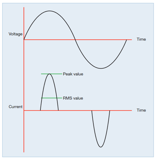
High Crest Factor Waveforms
At low load, the current is often at its most distorted. Current is drawn only at the peak of the voltage to charge the power supply’s reservoir capacitors and appears as a short pulse.
High Crest Factor is a result of high peak currents. Care should be taken while selecting current range on a Power Analyzer while measuring signals with high peaks. Selecting a range based on the RMS value of the signal can lead to clipping peak values resulting in errors. Always select ranges based on peak value when the Crest Factor is high.
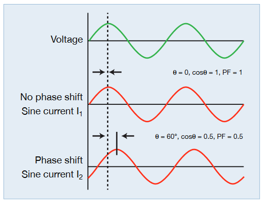
Low Power Factor
Under standby conditions the input current may be dominated by current flowing into the bulk capacitor across the input rectifier stage.
In this case, the current can be phase shifted up to 90 degrees.
In cases where current is in phase with voltage but the product VA is higher than active Watts, the Power factor can still be very low.
High sampling rate and good phase accuracy are important in power analyzers to ensure accuracy of measurement at low power factor.
Burst Mode Operation
Many power supplies operate in burst mode while in standby.In this mode, the power switching devices inside the power supply stop operating and the output voltage is maintained exclusively by the output smoothing capacitors. When the output voltage falls to a pre-determined level then the power supply switching starts again to top up the output capacitors.
In this mode current is drawn in bursts from the AC line. The bursts of current are irregular and vary in duration and size.
In addition, the power drawn by the product under test may simply change due to temperature or further power saving features.
For measurements of power in this circumstance the power analyzer must:
- Have a high sample rate and be able to sample power continuously.
- Take an average of the power over a period of time long enough to provide a stable result.
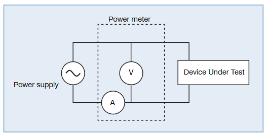
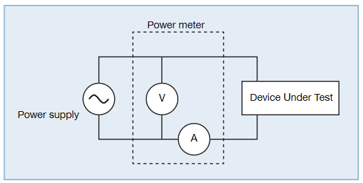
Making Connections
There are two ways a Voltmeter and Ammeter can be connected to make power measurements, as shown in the two figures above.
There is an inherent power drop across both Voltmeter impedance and current shunt, depending on amount of current flowing through each.
Typically, the voltmeter impedance is quite high (approx. 1Mohm) and the drop across it can be tens of mWs, depending on the input voltage amplitude. This is not a significant number while measuring 10s or 100s of watts, but in the case of standby power measurements, where power can be as low as 10mW, this can result in a significant error.
It is recommended to connect the current shunt on the load side for standby power measurement as shown in Figure 5. This will make sure that the current shunt only measures current flowing through the load and the drop across the voltage channel can be ignored. This will ensure minimum errors in low power measurements.
Keep in mind that for full load measurements, the drop across the current shunt will be relatively higher and the connection diagram shown in Figure 4 should be used.
Making a Basic Measurement
Set up the power analyzer to measure Watts. Conditions should be:
- Continuous sampling
- Recording Watts at a rate faster than 1 per second
- Averaging over a selectable time.
Example with a Tektronix PA1000
- Connect the analyzer as above.
- Select the 1A shunt for better low current accuracy.
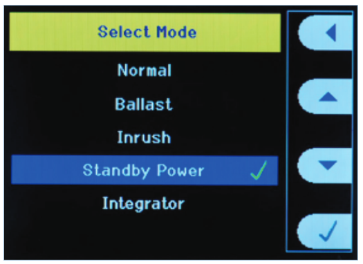
- Select Standby Mode.
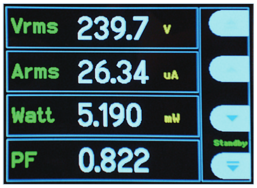
The analyzer will now make accurate standby measurements, sampling continuously at 1MHz without gaps and averaging the power measurement (watts) over the default 10 seconds.No further set up is required for this quick basic measurement.
This is an ideal basic measurement intended for continuous use in everyday product design and development.
If required, the averaging time can be changed in the menu system. 10 seconds is typical but if the measurement is unstable, increase the averaging time to suit the operating cycle.In case of difficulty, use the full compliance measurement ability of the PA1000 with PWRVIEW software.

Making Measurements to IEC62301 Ed.2:2011 and EN50564:2011
The Tektronix PA1000 power analyzer along with PWRVIEW software will also make measurements in full compliance to the above standards. This means that the analyzers meet the strict requirements for measurement methodology as well as accuracy.
IEC62301 Ed2 is important because this is the definitive measurement method reference by ENERGY STAR and the European regulation No 1275/2008 Standby and off mode electric power consumption of electrical and electronic household and office equipment.
Requirements of IEC62301 Ed.2
Please refer to the latest edition of the standard and confirm details before making compliance measurements.
Supply Voltage (IEC62310 Ed.2 Section 4.3)
- Nominal voltage and frequency for the region may be used but must be stable ±1%
- The total harmonic content (THC ) must not exceed 2%.(THC is a modified THD or total harmonic distortion including the first 13 harmonics only).
- Crest factor of the voltage (ratio of peak to RMS) must be between 1.34 and 1.49.
- Since any variation in these parameters will influence the standby power measurement they must be measured and confirmed simultaneously with each power measurement during the test. Simultaneous RMS and harmonic measurements are required.
- The normal AC line supply may meet these criteria, especially if the test connection is made close to the incoming supply or distribution transformer. If the supply does not meet the requirements than a synthetic AC source or line conditioner must be used.
Measurement Uncertainty (IEC62310 Ed.2 Section 4.4)
The IEC standard takes into account the difficulties discussed above and defines a measurement uncertainty that is based on both the level of power to be measured and the distortion and phase shift of the waveform.
To take into account both distortion and phase shift, Maximum Current Ratio (MCR) is defined.
MCR = Crest Factor / Power Factor
The required level of uncertainty, "U" can then be determined as in Figure 8.
Watts Measurement Procedure (IEC62301 Ed.2 Section 5.3)
There are three possible methods for determining the power in Watts:
1. Direct Method
This is the basic power analyzer front panel method described earlier. It is intended for rapid prototyping measurements on products that draw very stable power only.
This method is not recommended unless the power is very stable. This is rarely the case in most modern electronic equipment.
2. Average Reading Method
This method is a modified version of that used by previous versions of the standard (Ed.1).
a. For two measurement periods of not less than 10 minutes each the average power is determined.
b. The power measurements are checked for stability by calculating the rate of change of power (mW /h) between the two measurements. Only if the stability criteria are met is the measurement valid. If stability cannot be achieved the sampling method must be used.Since the measurement takes a minimum 20 minutes and does not apply to all product modes, the sampling method described below is preferred.
3. Sampling Method
This is the method recommended by the IEC. It is the fastest and applies to all possible product modes.
a. Power and other measurements are recorded every one second or less.
b. The product under test is energized for a minimum 15 minutes.
c. The first third of the data (5 minutes) is discarded.
d. Stability of the measurement is determined from a leastsquares linear regression through all the power measurements. Stability is established when the slope of the straight-line regression is either less than 10mW/h (for input power less than 1W) or less than 1% of the power if the power is greater than 1W.
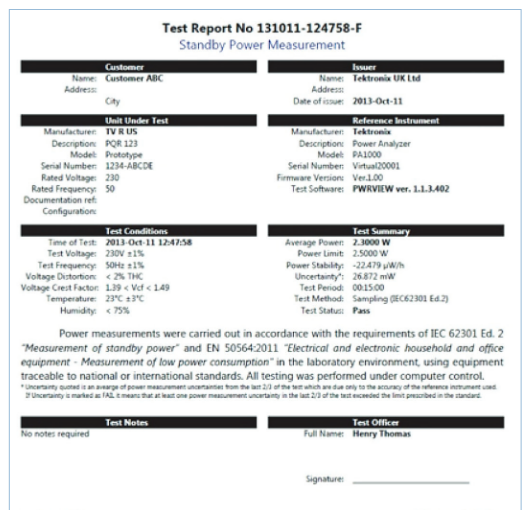
Test Report (IEC62301 Ed.2 Section 6)
The test report must contain details of the product, the test environment and the test laboratory as well as the measured data and measurement method.
General Power Analyzer Requirements (IEC62301 Ed.2 Section B.2)
- Determine all measurements (Volts, Amps, crest factors, THC as well as Watts) and record them simultaneously at an interval of less than 1 second.
- Sample continuously without gaps.
- Have a power resolution of 1mW or better.
- Ability to measure high crest factors of 3 or more.
- Minimum current range of less than 10mA.
- Signal over-range.
- Ability to switch auto-ranging off.
- Frequency response of at least 2kHz.
Making a Compliant Standby Power Measurement
Equipment Required
- AC Supply. Meeting the requirements discussed in section Supply Voltage (IEC62310 Ed.2 Section 4.3). For a test lab, this is normally a programmable AC Source that allows various voltage and frequency combinations to be certified.
- Power analyzer that meets the requirements of IEC62310 Ed.2 for uncertainty, measurement procedure and general characteristics as described earlier.
- Method to connect the test circuit (AC supply, power analyzer and product under test) safely and in accordance with IEC62301 Ed.2 Section B.4
- Method to record and report the measurement as required by IEC62301 Ed.2 Section 6.
Tektronix PA1000 Power Analyzer
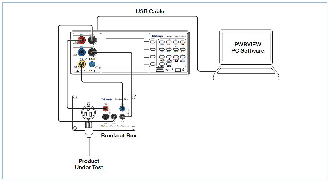
A Tektronix Breakout Box satisfies this requirement and is fitted with 4mm safety sockets for simple 1:1 connection to a Tektronix power analyzer.
A laptop with Tektronix PWRVIEW software installed and a USB connection.
Measurement Procedure
- Connect the supply, load and power analyzer using the Tektronix Breakout Box.
- Remember to use the VLO SOURCE connection on the Breakout Box.
- Apply the desired AC supply (e.g. 230V, 50Hz) and switch on the product under test.
- Switch on the power analyzer, connect the computer via USB and open the PWRVIEW application.
- Set up or wait until the product under test enters the desired standby mode.
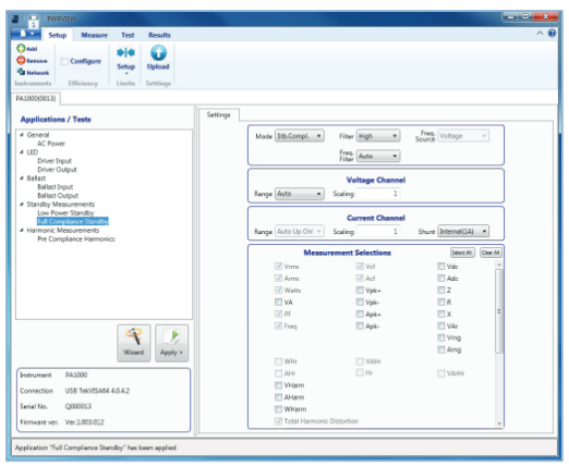
- In PWRVIEW, select the 'Full Compliance Standby' wizard to confirm the test set up or simply click 'Apply'.
- All the measurements required by IEC62301 Ed.2 are selected automatically.
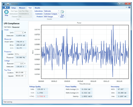
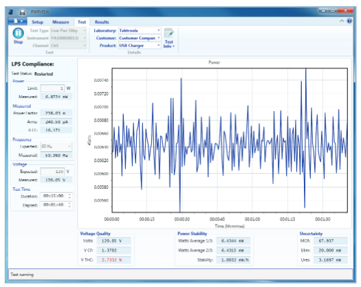
- Now click on the 'Test' tab and the "Start" in the ribbon.The compliance testing will begin.
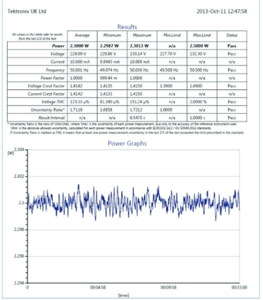
- The graph scales automatically and shows the power in watts on against the time of the measurement.
- Results are updated and displayed at a rate faster than the required 1/sec and recorded for reporting at the end of the test.
- The test duration should be a minimum of 15 minutes, extended if the requirements for stability are not met.
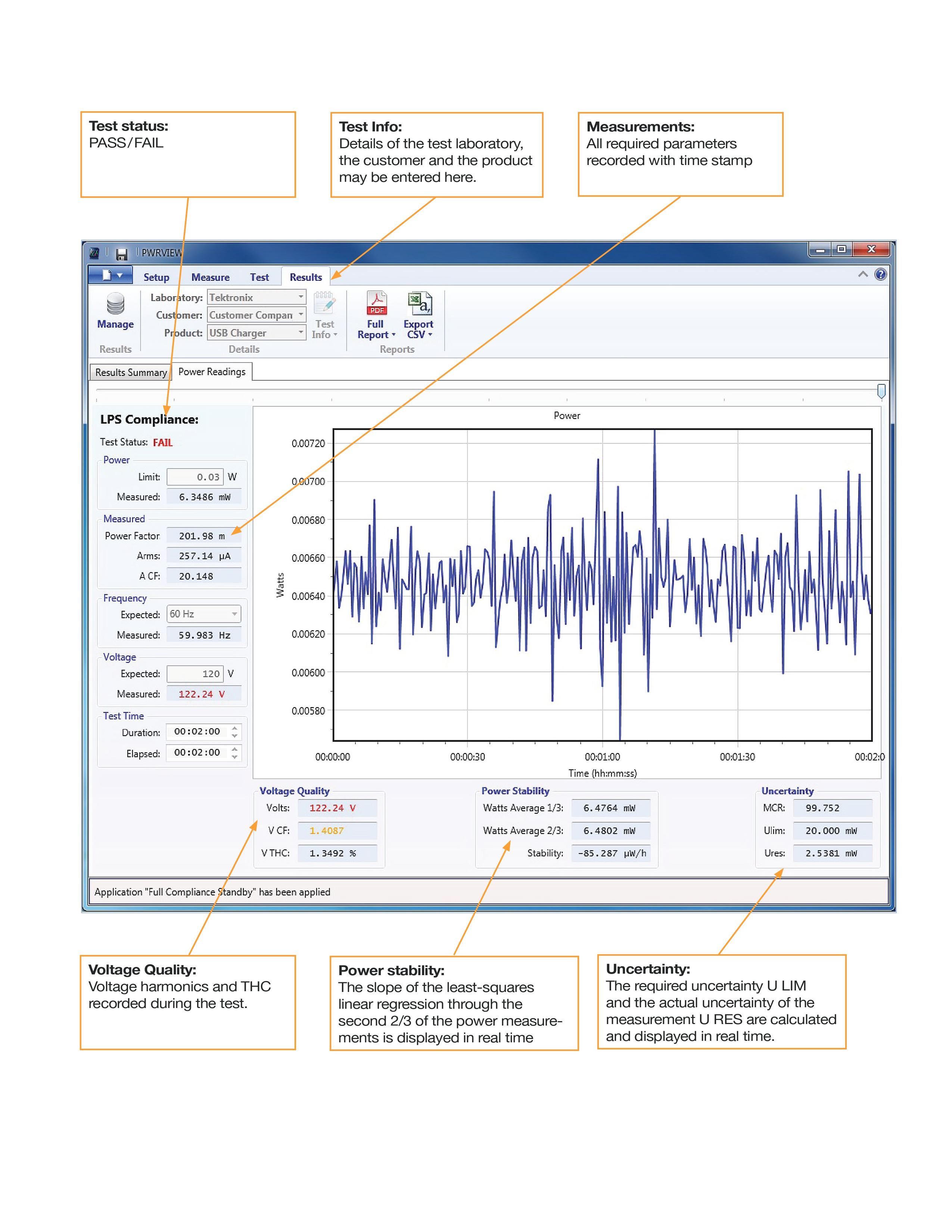
Reporting
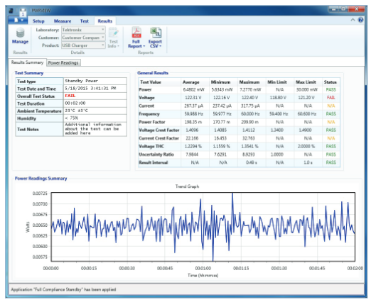
PWRVIEW provides powerful methods to review the measured data including Microsoft Excel compatible data export.
Click in the "Results" tab then select the data required by clicking the "Manage" symbol.
A full compliance report, including all certification notes may also be created as a pdf.
Tektronix Solutions
To make an accurate measurement of standby power, the following factors must be considered:
- The low levels of power and current.
- Highly distorted waveforms with high crest factors
- Low power factor.
- Burst mode operation
Tektronix PA1000 power analyzer is engineered to provide accurate measurements in these circumstances. In fact it is completely capable of fully complaint standby power measurements to IEC62310 Ed.2.
Meeting the Standard
How the PA1000 meets the requirements of IEC61000-3-2 Ed.2.
- Accuracy / Uncertainty
- High Crest Factors
- Low Power Factor
- Burst Mode Operation
- Sample continuously without gaps
- Report all measurements including watts and power quality simultaneously at intervals of less than 1 second
- Calculate stability using least square regression as specified
The PA1000 features a 1A current input as standard. The minimum range is 2mA. (IEC62301 Ed.2 requires a minimum of 10mA or less). The PA1000 will measure as low as 20uA and 5mW when in any standby mode (front panel or via PWRVIEW software).
The Tektronix power analyzers auto-range to a value determined by the peak values in a waveform. This guarantees measurements with high crest factors. If an over-range occurs, it is clearly signaled.
The MCR ratio of Current Crest Factor to Power Factor is determined in real time for each measurement while using full compliance test with PWRVIEW software.
The required uncertainty U LIM is calculated according to the requirements and the actual power analyzer uncertainty U RES is calculated from the actual measurement conditions including range and power factor.
The required and actual uncertainties are clearly displayed and reported to ensure compliance.
IEC62301 Ed.2 requires that a stable measurement is achieved and specifies stability exactly for various conditions. The Tektronix PA1000 Power Analyzer and PWRVIEW software:
Conclusion
The measurement of standby power is important to the engineer designing, testing and certifying power supplies and everyday domestic and office appliances. It is especially important to test and make sure the design will pass compliance, earlier in the design cycle, to avoid expensive board turns on tight deadlines later.
Tektronix PA1000 Power Analyzer, together with the PWRVIEW pc software, provides flexible and powerful tools to measure standby power.
During prototyping the analyzer's 1-click standby mode can be used to provide a 10-second measurement.
During design qualification and certification the full compliance abilities of the analyzers and PWRVIEW may be used to provide full compliance certification to IEC62301 Ed 2