Introduction
Raspberry Pi is a single-board small computer originally used as a tool to teach computer science to students. It has since grown in popularity due its compact size, low cost, modularity and open design. Each revision has added more capability to the original Raspberry Pi, and the computer is now widely used in applications beyond education.
Because of its limited computing power, the Raspberry Pi will not replace the regular PC in many areas. However, with its compact size, flexible I/O interfaces, low cost and builtin support for Python, it is an ideal platform to automate a lab test bench or a manufacturing test rack to control the instruments, capture waveform data and measurement results, and act as a hub to manage data from the instruments or remote access of the instruments.
This application note shows how to quickly set up a Raspberry Pi to automate a Tektronix 2 Series MSO Mixed Signal Oscilloscope and configure the instrument to control it remotely. You can also watch how to configure the setup in this video.
Setting up a Raspberry Pi
The setup for a Raspberry Pi as the controller PC for the lab bench is simple.
Basic requirement and setup:
- Raspberry Pi 4 with Raspberry Pi OS (formerly Raspbian)
- Python 3.7 or above
- PyUSB 1.2.1
- PyVISA 1.11.3
- PyVISA-py 0.5.2
The communication support between the oscilloscope and the Raspberry Pi is based on pyVISA.
Before starting the setup, make sure that the Raspberry Pi's software components are up to date. If they are not current, connect the Raspberry Pi to the network for the software updates.
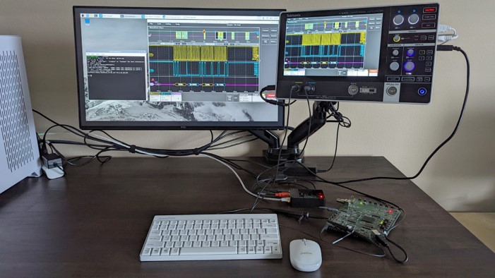
Figure 1: A quick setup for the Tektronix 2 Series MSO Mixed Signal Oscilloscope and a Raspberry Pi.
From the command prompt, enter sudo apt update && sudo apt upgrade -y
The update may take a few minutes or more, depending on when the system was last updated.
A few Python 3.x modules will be needed for setup. To install all the required modules, from the command prompt, enter the following commands for the update:
- sudo python3 -m pip install pyvisa
- sudo python3 -m pip install pyvisa-py
- sudo python3 -m pip install PyUSB
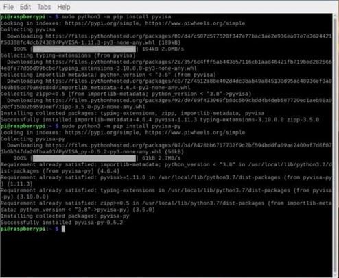
Figure 2: Required Python 3 modules for instrument control.
In some cases, a Raspberry Pi will only allow the root user to access the USB devices. To ensure that all users have access, modify the rule in the Raspberry Pi.
From the command prompt, enter
- sudo su
- echo 'SUBSYSTEM=="usb", MODE="0666", GROUP="usbusers"' >> /etc/udev/rules.d/99-com.rules • exit
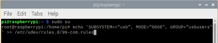
Figure 3: Modify the rule to allow all users to access the USB devices.
To commit the changes, restart the Raspberry Pi. From the command prompt, enter
- sudo reboot
To commit the changes, restart the Raspberry Pi. From the command prompt, enter
- sudo reboot
Setting up the connection with a Tektronix 2 Series MSO Mixed Signal Oscilloscope
Most entry-level oscilloscopes come with the USB device port for connectivity. To connect a Raspberry Pi with a 2 Series MSO
- Connect the USB device port on the right side of the instrument to the Raspberry Pi.
- Check if the Raspberry Pi is able to detect the 2 Series MSO. From the command prompt, enter
lsusb
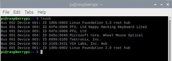
Figure 4: “Tektronix, Inc." is listed as one of the vendors of the attached USB devices.
The “Tektronix, Inc." device refers to the oscilloscope. If the Raspberry Pi does not detect the Tektronix device, repeat the steps above with a different USB port or cable.
To validate that the Raspberry Pi can communicate with the oscilloscope, launch Python 3.0. From the command prompt, enter • python3
Then enter the following to check the oscilloscope's VISA descriptor:
- >>> import pyvisa
- >>> rm = pyvisa.ResourceManager()
- >>> rm.list_resources()
- ('ASRL/dev/ttyAMA0::INSTR', 'USB0::1689::261::PQ100125::0::INSTR')
- >>> inst = rm.open_resource('USB0::1689::261::PQ100125::0::INSTR')
- >>> print(inst.query("*IDN?"))
The return from the rm.list_resources() will display the VISA descriptor. After it lists the correct VISA descriptor, enter
- inst = rm.open_resource(<VISA descriptor>) to connect the Raspberry Pi to the oscilloscope.
To confirm the communication, enter an *IDN? query. If the return string lists the correct model number and serial number, then the Raspberry Pi is able to communicate with the oscilloscope. (See Figure 5 below.)
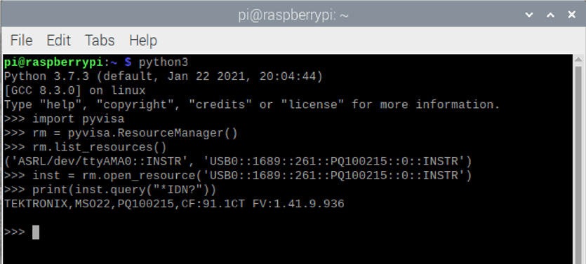
Figure 5: Validate the communication using *IDN? query command.
In addition to the 2 Series MSO, other entry-level oscilloscopes such as the Tektronix TBS2000B and TBS1000C Digital Storage Oscilloscopes are also compatible with the Raspberry Pi setup.
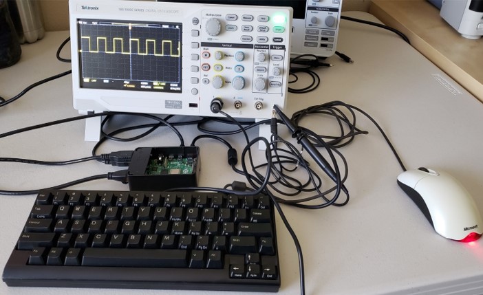
Figure 6: Connecting to the Tektronix TBS1000C Digital Storage Oscilloscope.
Example script
Following is a Python example script for querying waveform data and plot. This example script can also be downloaded and copied from the attached file named example_script.txt import time # std module
import pyvisa as visa # http://github.com/hgrecco/pyvisa - pyvisa for connectivity import matplotlib.pyplot as plt # http://matplotlib.org/ - for plotting import numpy as np # http://www.numpy.org
# VISA descriptor to identify the test and measurement device
# Please update the VISA descriptor from the query result from pyvisa visa_address = 'USB0::1689::261::Q300209::0::INSTR'
rm = visa.ResourceManager() scope = rm.open_resource(visa_address) scope.timout = 10000 # ms scope.encoding = 'latin_1' scope.read_termination = '\n' scope.write_termination = None scope.write('*cls') # clear ESR scope.write('header OFF')
# acquisition
scope.write('acquire:state OFF') # stop
scope.write('acquire:stopafter SEQUENCE;state ON') # single r = scope.query('*opc?')
# curve configuration
scope.write('data:encdg SRIBINARY') # signed integer scope.write('data:source CH1') scope.write('data:start 1')
acq_record = int(scope.query('horizontal:recordlength?')) scope.write('data:stop {}'.format(acq_record)) scope.write('wfmoutpre:byt_n 1') # 1 byte per sample
# data query
bin_wave = scope.query_binary_values('curve?', datatype='b', container=np.array, chunk_size = 1024**2)
# retrieve scaling factors
wfm_record = int(scope.query('wfmoutpre:nr_pt?')) pre_trig_record = int(scope.query('wfmoutpre:pt_off?')) t_scale = float(scope.query('wfmoutpre:xincr?'))
t_sub = float(scope.query('wfmoutpre:xzero?')) # sub-sample trigger correction v_scale = float(scope.query('wfmoutpre:ymult?')) # volts / level v_off = float(scope.query('wfmoutpre:yzero?')) # reference voltage v_pos = float(scope.query('wfmoutpre:yoff?')) # reference position (level)
# disconnect scope.close() rm.close()
# create scaled vectors
# horizontal (time)
total_time = t_scale * wfm_record
t_start = (-pre_trig_record * t_scale) + t_sub t_stop = t_start + total_time
scaled_time = np.linspace(t_start, t_stop, num=wfm_record, endpoint=False)
# vertical (voltage)
unscaled_wave = np.array(bin_wave, dtype='double') # data type conversion scaled_wave = (unscaled_wave - v_pos) * v_scale + v_off
# plotting
plt.plot(scaled_time, scaled_wave) plt.title('channel 1') # plot label plt.xlabel('time (seconds)') # x label plt.ylabel('voltage (volts)') # y label print(“look for plot window...") plt.show()
Setting up the TightVNC (optional)
This is optional for the user who prefers to set up VNC on the Raspberry Pi to remote into it.
To update to the latest version, from the command prompt, enter
- sudo apt update && sudo apt upgrade -y
Then to install the VNC Server, from the command prompt, enter
- sudo apt install tightvncserver
For the initial setup for the VNC server, from the command prompt, enter
- •vncserver
Because this is the initial setup, the command prompt will ask for a password. Enter a password composed of eight characters. The password will automatically be shortened to eight characters.
Reenter the password for verification.
When asked if it is a viewer-only password, select No.
On the other PC, install the TightVNC client at tightvnc.com.
Once installed, start the TightVNC Viewer. In the connection window, enter the Raspberry Pi's IP address and the default port number (5901).
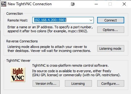
Figure 7: TightVNC viewer connection window.
To look up the IP address in Raspberry Pi, use the command ifconfig.
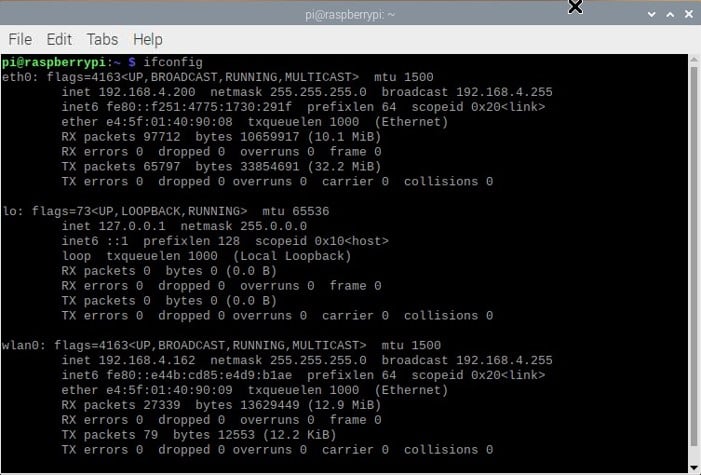
Figure 8: Look up the IP address using the command ifconfig
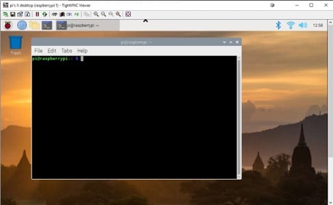
Figure 9: TightVNC viewer on the remote PC.