Introduction
Electric vehicles are taking over the transportation market, and this means that the demand for high performing battery packs is also on the rise. To ensure that every vehicle meets our expectations for power output, charging speed, safety and lifespan, battery and car manufacturers both must test the battery packs for defects and performance. This testing can be a bottleneck in the manufacturing process, so test solutions that reduce time or increase test density are highly desirable. One of the most useful measurements for a battery cell or pack is the open circuit voltage (OCV), but the considerations that must be made at the module or pack level differ from the cell level. This application note describes several ways of measuring open circuit voltage on a battery pack including at the full pack level, on individual cells that are connected in parallel and on individual cells connected in series.
Battery Open Circuit Voltage
The open circuit voltage on any device is the voltage when no load is connected to the rest of the circuit. In the case of a battery, the OCV measurement reflects the potential difference between the two electrodes. This potential difference is a direct result of the battery’s chemistry and is an indicator of the state of charge (SOC) or how much energy is stored in the battery at any given time. In fact, this measurement is often used to characterize the relationship between SOC and OCV at the cell level. Monitoring the cell OCV over time as the cell self-discharges can also expose defects in the battery cell and allow manufacturers to grade the quality of the battery.
Battery packs are comprised of many cells that are connected together in series or parallel to achieve the desired voltage and current output and energy storage. The cells may be connected into smaller subgroups called modules, and then those modules may be combined to form the pack. The open circuit voltage in this case indicates the energy that is stored in the entire pack or module. This could be used for verifying the charging or discharging behavior in the vehicle, monitoring self-discharge behavior or modeling pack behavior in varying environmental conditions.
It may also be necessary to measure the open circuit voltage of the individual cells in addition to the voltage of the pack as a whole. This is especially useful for judging the cell balancing routines during charging and discharging that prevent cell stress and validating monitoring in the battery management systems. Measuring the open circuit voltage of the individual cells may also help identify single defective cells in the pack. A key difference between measuring the cells and the entire pack is that each of the cells is less than 10 V and typically it is desirable to measure smaller resolution at the cell level than at the pack level, which may be hundreds or thousands of volts. Therefore, we must consider special methods to isolate the voltage of each cell from the rest of the pack.
Measuring Open Circuit Voltage of the Entire Pack
Even though the modules and packs are made up of cells, the entire group can be treated as a single larger battery and the voltage can be measured directly across those two terminals with a digital multimeter (DMM) as shown in Figure 1.
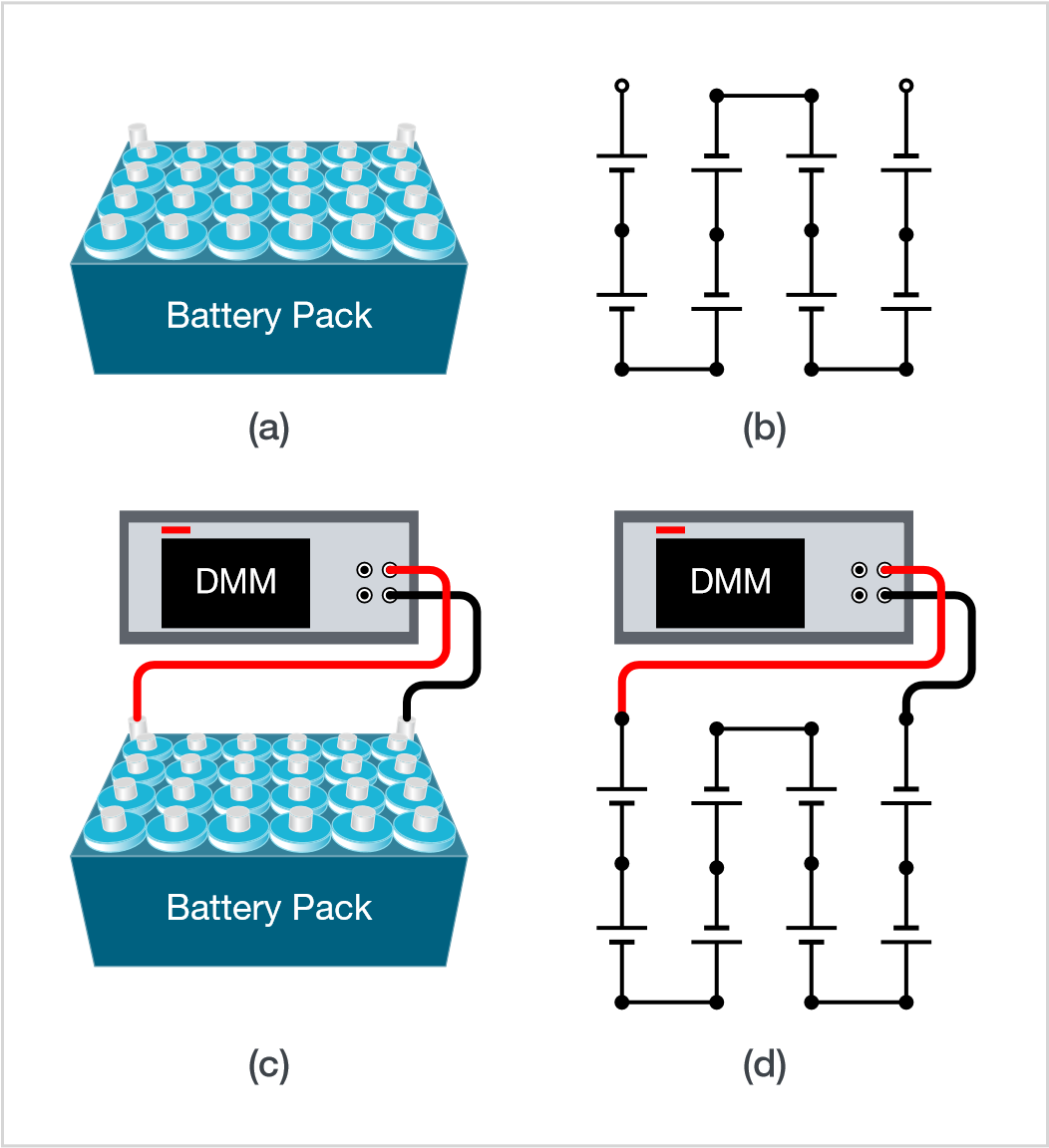
At the pack or module level, the output voltages and currents are much larger than at the cell level. When choosing a DMM to measure the OCV of a pack, ensure that the DMM has high input impedance (10 MΩ or greater) to prevent the battery from discharging, which can change your measurement or cause damage to the test system in the event of high currents. Also check that the applied voltage is within the limitations of the DMM. If the battery module or pack is capable of high current output consider adding fuses to the test system to protect the DMM or other test equipment from damage.
Measuring Open Circuit Voltage on Cells Connected in Parallel
Battery cells are connected in parallel to increase the current output in the system. In this case, the open circuit voltage remains the same across the combination of the cells. To measure the open circuit voltage of an individual cell in the parallel combination, connect the DMM directly across the cell as shown in Figure 2.

The considerations for this measurement are similar to that of just a single cell. High voltage exposure is not a concern for this configuration, however any short in the system can lead to a high current event as shown in Figure 3.
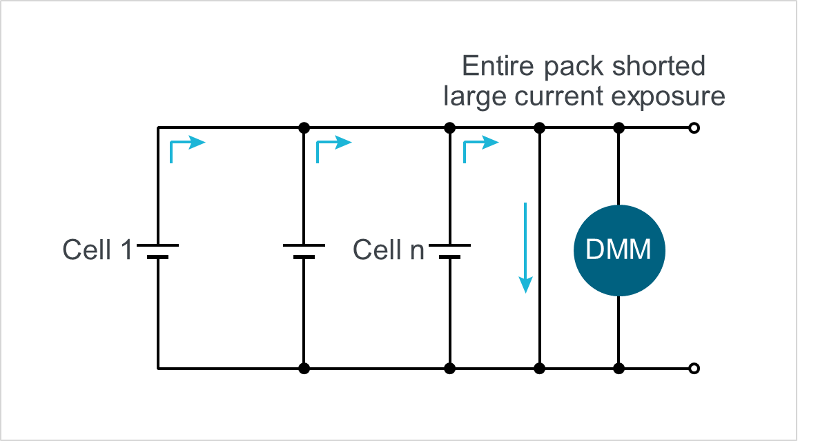
To prevent damage to the batteries or the test equipment, take care to prevent any shorts during connections. Also add fuses to the test system to protect the test equipment from high current.
Measuring Open Circuit Voltage on Cells Connected in Series
Battery cells are connected in series to increase the voltage potential in the system. The current output remains the same across all the cells. Since shorts are less likely to cause a severe current event, fusing is not as critical as when cells are wired in parallel. We must instead consider the instrument’s exposure to high voltage.
A large number of cells are wired in series in Figure 4a. If we assume one terminal of the battery pack is connected to ground, we can measure the open circuit voltage across each cell. This works because DMMs measure differential voltage, or the voltage potential at HI minus the voltage potential at LO. With the left side terminal of the battery connected to ground, the LO terminal of the DMM ends up floating above the voltage of common ground. This voltage is known as the common mode voltage. If this common mode voltage gets too high, the DMM’s input terminals can be damaged. For a DMM with a maximum common mode voltage of 500 V, the measurement of the final cell in the series would damage the low terminal of the DMM.
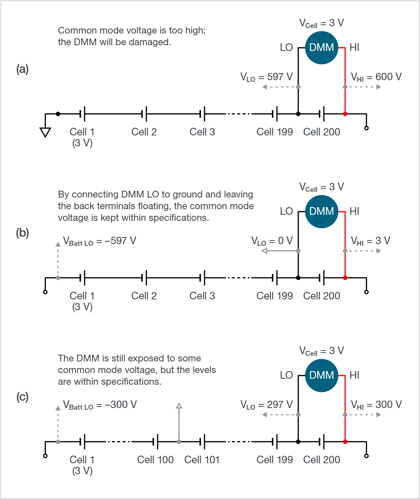
We can avoid this by moving our common ground connection with the LO terminal of the DMM as shown in Figure 4b. Battery potential is only relative to the electrodes. When fully charged, the cathode is at a voltage potential higher than the anode, typically equal to the nominal voltage of the battery. With cells connected in series, this potential difference increases across each cell, but there is still no reference to ground. Therefore, we are free to connect any point in the circuit to common ground, ensuring that our DMM LO terminal is set to 0 V and is protected from damage.
Other variations of this method can also be used. For example, the reference ground could be permanently placed in the center of the pack. In this case, the pack potential would be at one half of the full potential of the pack below ground at the low potential end and above ground at the high potential end. Provided this voltage is within the common mode voltage specifications of the DMM, the DMM is protected from damage.
Measuring Cells in Series and Parallel Combinations
Most battery packs contain some combination of cells in series and in parallel. For example, modules may be broken down into a few groups of parallel cells that are connected in series and then that module is connected in series to other modules. In these cases, it is important to keep in mind both the need for fuse protection against high current events and proper grounding to prevent high common mode voltage. At each potential measurement point, consider the voltage potentials and short circuit current levels.
Multichannel Solutions
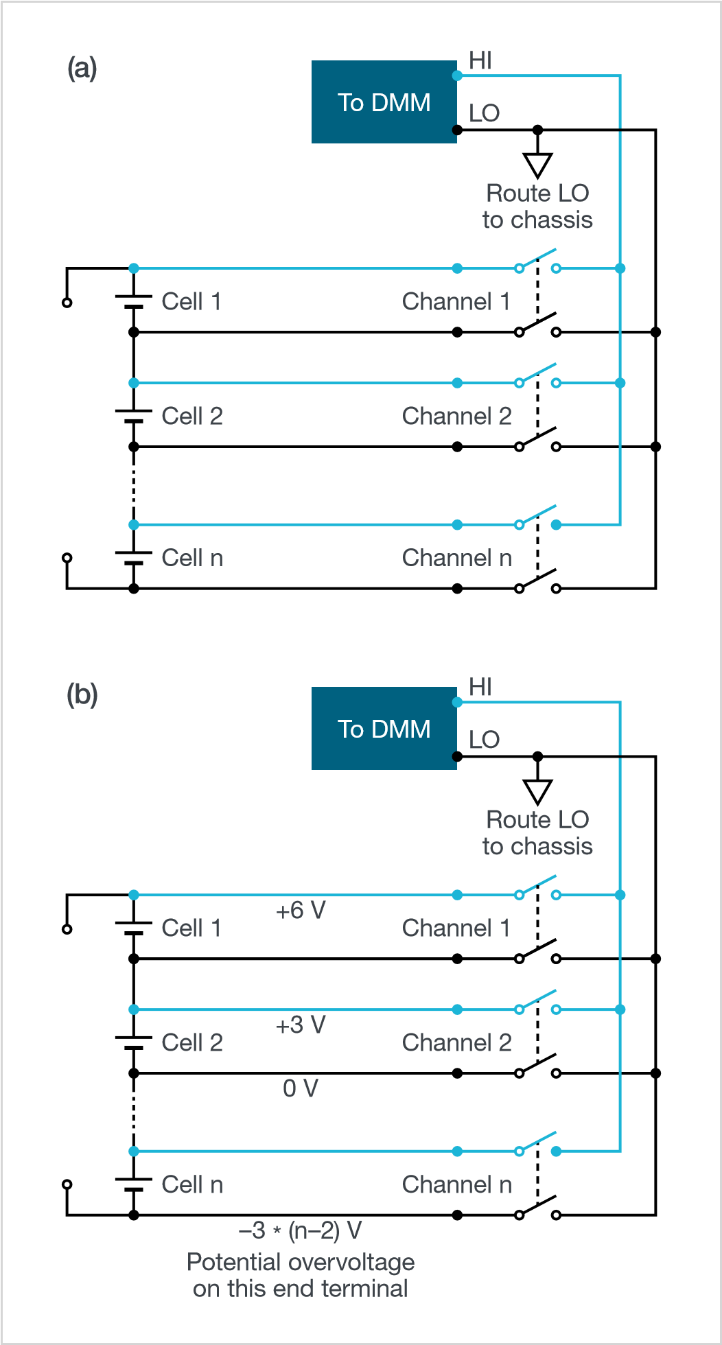
Battery packs can contain hundreds of cells so one way to reduce the time requirements on testing and equipment costs is to use a multichannel solution. A multichannel DMM uses a switching system to measure multiple signals sequentially without needing to rewire. When using a multichannel system, keep in mind that the switching pathways will introduce some uncertainty to your measurement. The relays used in switch cards also have maximum signal level and common mode voltage specifications that must be considered when sizing fusing or measuring many cells connected together.
In particular, the common mode voltage specification must be carefully considered, as the specification applies to all channels and may apply between signal paths or between signal paths and chassis ground. For cell configurations that may expose the DMM to high common mode voltages, routing the LO terminal to ground at all times is enough to protect the DMM, but the switch terminals that are unused may still be exposed to high common mode voltages. In that situation, the switch system must be rated to handle the highest voltage that could be present in the pack. Figure 5 shows an example of using a multichannel solution to measure several cells connected in series.
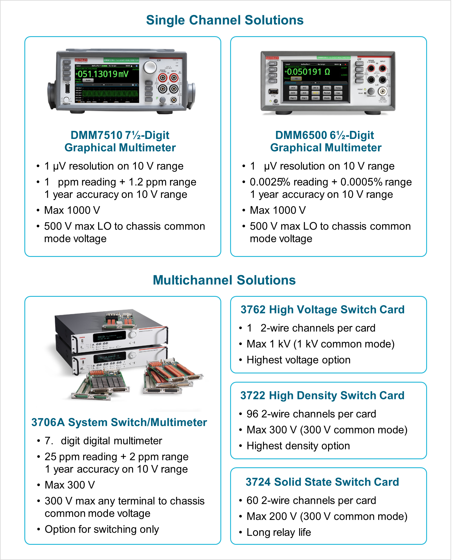
The Keithley Solution
Keithley Instruments has several options for measuring open circuit voltages on packs shown in Figure 6. The DMM7510’s 7.5-digit resolution and high accuracy is great for critical tests like characterization and selfdischarge monitoring, giving you an accurate picture of small changes in the open circuit voltage. The DMM6500 provides slightly less resolution and accuracy at only 6.5 digits but is good for monitoring the open circuit voltage as part of other tests, where minor changes are not necessarily important. The Keithley 3706A System Switch and Multimeter is a high density multichannel DMM that has six built-in slots for switching cards. Switch card options include high density cards for up to 576 2-wire channels or high voltage cards to measure up to 1000 V.
Conclusion
There are many reasons for measuring the open circuit voltage on a battery pack and several different ways to measure it. With any high energy system, the most important consideration to make is how much energy the system will be exposed to and then place the necessary test routines or protection in place to get the best measurement possible.