Introduction
As battery-powered devices have become a staple of everyday life, battery performance has become a critical factor in device design. Single use, or primary, disposable batteries remain ubiquitous in their usage, often used to power remote controllers, flashlights, and radios. These are most often seen in the form of alkaline batteries or the older zinc-carbon batteries. However, rechargeable, or secondary, batteries are commonly and increasingly used in place of disposable batteries in electronic devices such as laptops, mobile phones, and digital cameras. Common types of rechargeable batteries include Li-ion (Lithium Ion) and Ni-MH (Nickel Metal Hydride). Because of the criticality of battery performance to everyday life, and the wide range of battery types, test and design engineers working with battery powered devices need a way to optimize their device’s performance and battery life.
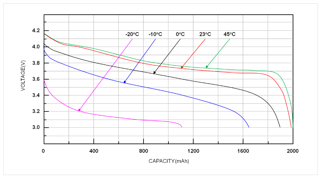
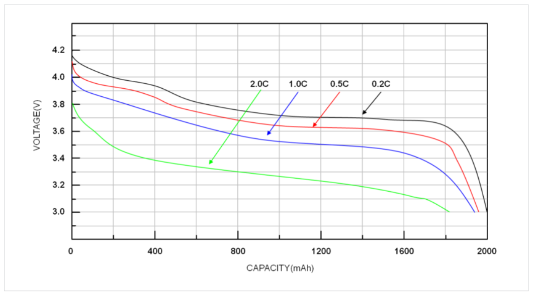
When optimizing a device for battery life, it may be important to analyze the performance of a given battery type over one charge cycle. This is done through a discharge curve which shows the battery’s change in voltage over time when connected to a load. A battery’s performance over one charge cycle varies greatly with many different factors including size, temperature, material, and discharge current. A battery’s performance is also heavily dependent on the Equivalent Series Resistance, ESR, of the battery. The ESR of a battery is the inherent internal resistance, depicted as the resistor in a battery’s Thevenin equivalent circuit. Examples of discharge curves, as well as this variance in performance, can be seen in Figure 1, where a lower temperature increases the ESR, which in turn increases the battery’s discharge rate. This behavior can also be observed in Figure 2, where a higher load current also leads to an increase in discharge rate.
When Keithley’s KickStart Software, and the KickStart Battery Simulator App, is paired with the 2281S model generation becomes simple. KickStart Software’s intuitive interface, model editing abilities, and battery model repository allow the test or design engineer to create battery models at different conditions and test their device against these various models quickly.
To optimize the battery life of a device, it may be useful to test the device’s performance at different “States of Charge”, SOC, and “Open Circuit Voltage”, VOC For instance, a lithium polymer battery typically operates over a range of 4.2 V fully charged to 3 V. Design and test engineers will want to ensure their device operates properly at all voltages or shuts down before low power causes instability. Keithley’s KickStart Software makes this easy, allowing the user to set the SOC of their simulated battery, even during simulation. The KickStart Software also allows for dynamic and static battery models, where the simulated battery’s SOC can decrease in real time according to the applied load, or where the model stays at the exact SOC and VOC set by the user. Because of these powerful data collection tools, easy to use interface, and the “all-in-one” nature of Keithley’s KickStart Software, the KickStart Battery Simulator App offers unprecedented value and simplicity in quickly simulating various battery models for device testing.
Application
The objective of this app note is to demonstrate the abilities of KickStart software’s Battery Simulator App, and the 2281S through analyzing the battery performance of a smart,wearable medical device.
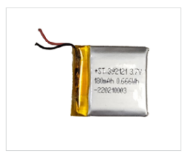
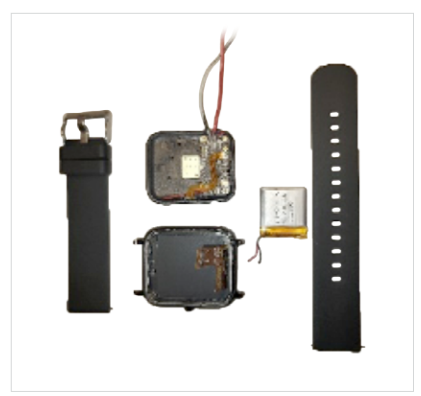
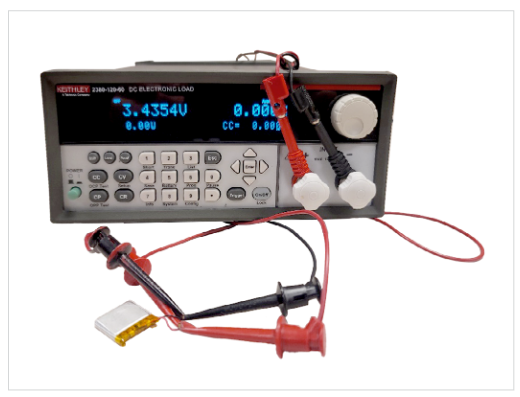
Recently, Smart or Internet of Things (IoT), wearables have seen a marked uptick in adoption. Smart wearables, with their ability to monitor the user’s vitals, offer new ways of tracking patient health and worker safety. These devices are intended to collect data over long periods of time and, as such, there is a need to test them to optimize both battery life and efficiency. The Battery Simulator App within KickStart software makes this testing quick and simple. However, before the device’s performance can be optimized, models of the battery must be made. Battery models can be generated in KickStart software by discharging a battery using a Keithley Series 2380 DC Electronic Load. This app note will focus on the KALINCO Smart Fitness Tracker and its built-in battery. The fitness tracker is displayed in Figures 3–5.

Creating a model with the 2380 Electronic Load
Figure 6 shows the configuration used in the KickStart software to create a discharge model of the fitness tracker’s battery using the Keithley Series 2380 DC Electronic Load. To start model generation, open the KickStart Software. The 2380 should be detected automatically and displayed in the instruments tab on the left-hand side of the screen. Double click or drag the 2380 icon into the center of the screen. This will launch a new window asking for your desired app. Select Battery Simulator and edit the parameters to reflect the qualities of the device under test. When a model is generated using a Series 2380 instrument, the device being modeled must be in a fully charged state. An example of the Generate Discharge Model screen and its relevant parameters are shown in Figure 7.
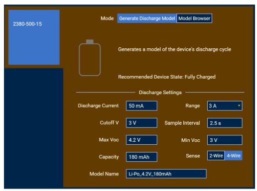
When generating a discharge model, the specific parameters corresponding to your battery as outlined by the battery’s datasheet must be used. The discharge current is the maximum amount of current that will be drawn from the battery during the test. Because this discharge model operates in constant current mode, this current will be present throughout the duration of model generation. For this example, discharge current will be set to 50 mA. Next, the range was set at the low range option. For the 2380-120-60 this is 6 A and for the 2380-500-15 and 2380-500-30 this is 3 A. Next, the “Cutoff V” is the end voltage condition for generating discharge models. Once the battery voltage reaches this level the data collection is complete. For this example, the Cutoff voltage was set to 3 V. The sample interval is the time between data measurements. This was left as 2.5 seconds. The Max and Min VOC values are the maximum and minimum open circuit voltages of the battery model after generation. These were set for 4.2 V and 3.0 V respectively. The capacity is the total energy in the battery, measured in Amp hours. For the battery included with the Kalinco Smart Fitness Tracker, the capacity is listed as 180 mAh.
The “Sense” setting corresponds to the use of either 2-wire or 4-wire sense for taking measurements. When measuring voltage or resistance within a circuit, an instrument will generally source a current, measure the voltage, and calculate the resistance. In a 2-wire sense setup the current source and voltage measurement happen at the same leads, while a 4-wire sense uses separate leads for the current source and the voltage measurement. Because of this, 2-wire measurements will introduce lead resistance into the measurement. For DUTs with high resistances, the added resistance from the test leads may not lead to significant error. However, in cases where resistance is 1 kΩ or less test lead resistance may lead to significant error. Therefore, for the best accuracy, this was set to 4-Wire. Lastly, after these parameters are set a model name can be chosen and the blue play button can be pressed to begin the data collection. As the voltage at the battery terminals, Vt, decreases, the progress bar will fill up at the bottom of the KickStart Battery Simulator App screen.
Once data collection has completed, the file will be automatically exported to the following directory: “C:\ Users\%userprofile%\AppData\Local\Keithley\KickStart\ BatterySimulator\ImportedModels”. For the purposes of this demonstration, another discharge model is generated with the battery enclosed in a temperature-controlled environment at about 5°C.
Simulating the Model with the 2281S Battery Simulator
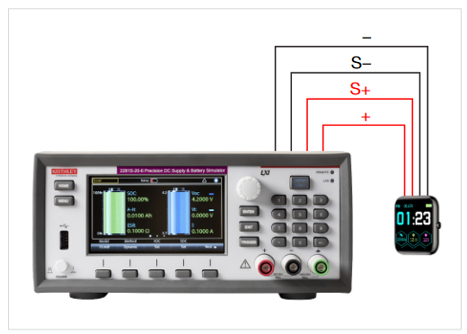
After the battery models have been generated using the 2380, simulation and analysis can begin. Figure 8 shows a 4-wire sense connection between the Keithley 2281S, connected to KickStart Software’s Battery Simulator, and the Kalinco fitness tracker. However, the model that was generated using the 2380 must first be transferred to the 2281S. To do so you must import a new battery model by navigating to the Model Browser tab. An example of this screen is shown in Figure 9. In addition to any usergenerated models, the KickStart Battery Simulator App comes pre-loaded with several models of common batteries, which can be seen in the “available models” drop-down menu. Next, click “Import Model File.” The software will prompt for a *.csv file. Simply select the preferred file of the appropriate type and the new model will be added to the list of available models stored in the app. After selecting the model, you’ll see the graph and table on this screen populated with data. Custom battery models can also be edited or deleted within the Model Browser.
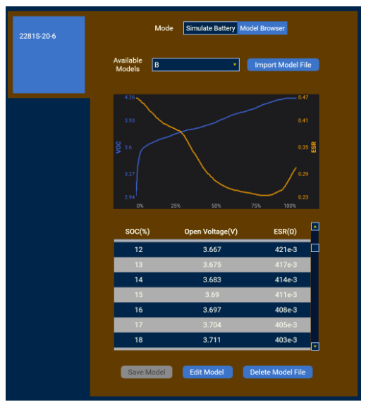
To edit a model, select the preferred model from the “Available Models” dropdown menu and navigate towards the bottom of the window. Click “Edit Model.” This will allow you to interact with the model table and change the Open Voltage and ESR values by double clicking on any individual cell. To keep the edits, click the “Save Model” button. To dismiss the changes, click “Cancel Edit.” Once the model is imported, and the model entries are confirmed to be as desired, switch the view to the Simulate Battery tab. Next select the desired model from the “Selected Model” dropdown. Lastly, ensure SOC is set to 100% and all simulation parameters are as desired. An example of this view with simulation parameters is shown in Figure 10.
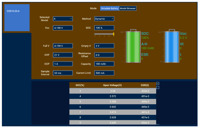
The KickStart Battery Simulator app offers two methods of simulation: “dynamic” and “static”. A dynamic model will simulate the discharge of battery, lowering its capacity and VOC as a load is applied, while a static model holds one SOC constant. A slider is also located underneath SOC to easily slide through battery percentages. For the purposes of this example, this should be set to dynamic. There are additionally three protection parameters which should be set before starting the simulation. The first two are “Over-Voltage Protection”, OVP, and “Over-Current Protection”, OCP. These two settings will stop the simulation if the voltage or current of the simulated battery exceeds this value. For this example, these were left at the default value of 21 V for OVP and 1 A for OCP. The third setting is the “Current Limit”. This is the maximum value the simulated battery will output. This was set at 500 mA. An additional setting, “Resistance Offset”, allows for adjustments to the ESR value by adding a positive or negative offset. This was left at 0 Ω. With these settings now in place, you can start the model simulation and data collection by pressing the blue play button at the bottom of the KickStart Software screen.
Once the run button is pressed, the smart watch is powered, and data will begin filling the table and graph. The battery icons featured in the simulation settings view allow the user to monitor the state of the simulated battery in a visual format. These indicators update in real time and allow for the visualization of key parameters such as SOC, capacity, ESR, VOC, voltage at the terminal (Vt), and current. From here, the battery usage of the smart watch in various conditions can be determined. For the purposes of this application two conditions were determined. The first was an exercise mode which tracks fitness information such as heart rate, steps, and time. The second was a timer mode which forces the screen to stay on. These two conditions were then run for one hour each, using both the room temperature, about 20°C, battery model and the 5°C, cold model.
Results and Added Value
To see the simulation data or model data in a larger tabular or graphical view, select the “Table” or “Graph” tabs. In the table tab, columns can be renamed or hidden, and statistics such as minimum, maximum, mean, standard deviation, and coefficient of variation can be viewed. Under the graph tab, the VOC, current, and ESR can be viewed. The graph tools allow for viewing additional statistics under the curve, zooming in to see areas of interest, and changing the axes from linear scale to logarithmic.
In addition to the data collected with the KickStart Software, the behavior of the device at low SOC can be characterized. For instance, while the Kalinco Fitness Tracker stayed powered on the end of the charge around 3 V, the screen was visibly dimmer, the device was noticeably slower, and, when powered off, would not power back on. Figure 11 shows examples the table and graph tabs within the KickStart Software, after data has been collected.
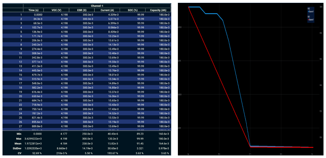
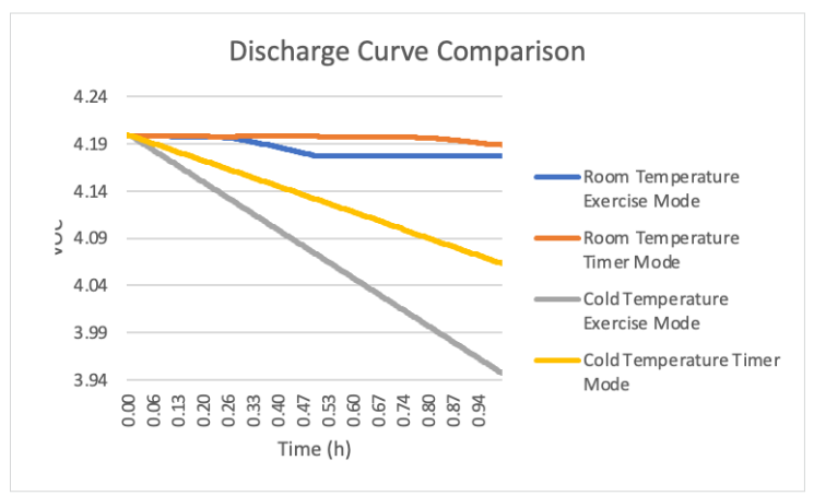
Figure 11 shows the changes in SOC and VOC as the battery discharges, as well as the table containing all the measurements taken over the simulation. Figure 12 combines each discharge curve from every test into a single graph to compare battery life over the subsequent runs. From this, it can be seen that the battery discharges much faster at colder temperatures. Both the cold temperature exercise mode and cold temperature timer mode dropped to a lower voltage compared to the room temperature models in the same amount of time. After these simulations were performed and the data was collected, a test engineer could instantly “recharge” their model back to 100% or switch to a different model for further testing. For the purposes of this example, the power consumptions of two device operating modes were compared with two separate battery models. However, a test engineer may be interested in making improvements to a certain device behavior, rather than comparing between different modes. Battery simulation is perfect for this because they can restart the model after changes to the device design or software and know that the simulated battery behavior is the same for each test.
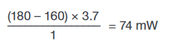
It should also be noted that although the KickStart Software, and the Battery Simulator App, does not directly output power consumed, it can easily be calculated using the formula:

To do so, just the starting capacity, capacity at the end of simulation, time of simulation, and nominal voltage are needed. Using the Room Temperature Exercise model as an example, the difference between the beginning and ending capacities of 180 mAh and 160 mAh, 20 mAh, is converted into mWh by multiplying by the nominal voltage of 3.7 V. This leads to a Wh capacitity of 74 mWh. With a simulation time of one hour this leads to 74 mW of power consumed:
Conclusion
In conclusion, KickStart software’s battery simulator app paired with the 2281S enables easy repetition of tests under various conditions and allows for a simple method to generate battery models for simulation. The simplicity afforded by a total software solution means that it is possible for anyone to set up and run tests quickly and efficiently – from students to technicians to design engineers.
Kickstart software provides a no code solution to generate battery models with a few simple mouse clicks and straight forward battery simulation tools. Simulation makes it easy to optimize battery life and overall performance without needing to test tens of dozens of batteries individually. Through battery simulation, tests are repeatable with consistent comparable performance, and with the power of software, data gathered during these tests can be saved, visualized, and analyzed all in one place on the PC.
Find more valuable resources at TEK.COM
Copyright © Tektronix. All rights reserved. Tektronix products are covered by U.S. and foreign patents, issued and pending. Information in this publication supersedes that in all previously published material. Specification and price change privileges reserved. TEKTRONIX and TEK are registered trademarks of Tektronix, Inc. All other trade names referenced are the service marks, trademarks or registered trademarks of their respective companies.
120922 1KW-73977-0