Contact us
Call us at
Available 6:00 AM – 5:00 PM (PST) Business Days
Download
Download Manuals, Datasheets, Software and more:
Feedback
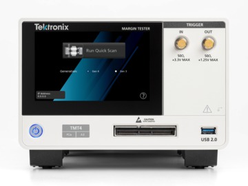
TMT4 Margin Tester
Margin Tester Datasheet
The products on this datasheet are no longer being sold by Tektronix.
The products on this datasheet are no longer being sold by Tektronix.
View Tektronix Encore for reconditioned test equipment.
Check support and warranty status for these products.
PCIe link health evaluation in under 2 minutes.
A first-to-market PCIe testing tool like no other
The first of its kind, the Tektronix TMT4 Margin Tester is a certified PCIe testing tool that enables fast and easy evaluation of the link health of PCIe Gen 3 (8 GT/s) and Gen 4 (16 GT/s) devices. Supporting most common PCIe form factors like CEM, M.2, U.2, U.3, and E1, it is capable of linking with the majority of the PCIe devices available today.
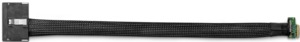
Using a single PCIe-enabled 16-lane high density cable and connectors, the Margin Tester can be adapted to test system boards or add-in cards in seconds. Complete evaluation of the transmitter and receiver link health of PCIe Gen 3 and Gen 4 devices can be conducted in as little as 2 minutes. It is truly in a class of its own.
The TMT4 Margin Tester re-imagines the way that PCIe link health testing is performed. As an active link partner with the device under test (DUT), the instrument is capable of controlling presets and link training parameters of the DUT directly, providing insights into potential design flaws on a lane-by-lane or preset-by-preset basis. Evaluating the link health of your PCIe Gen 3 and Gen 4 devices has never been easier.
Time to insight and ease of use at the forefront of Tektronix innovation
The TMT4 Margin Tester was specially designed for the modern engineer. Today, testing times and the complexity of equipment setups can often lead to testing bottlenecks for design and validation engineers. The TMT4 was designed with these two challenges in mind and has answered the call when it comes to testing times and ease of use.
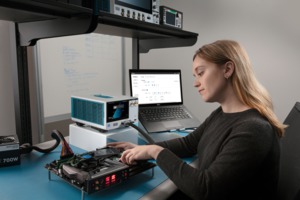
The TMT4 can be set up and ready to test in as little as 5 minutes, and an optimized user interface makes testing easier than ever. With the Margin Tester, Tektronix has responded to the needs of the modern engineer when it comes to the evaluation of link health in PCIe Gen 3 and Gen 4 devices.
Key features
- PCIe Gen 3 (8 GT/s) and Gen 4 (16 GT/s) speeds supported
- Link widths up to 16 lanes supported
- Support for CEM, M.2, U.2, U.3, and E1 devices
- Two scan options: Quick Scan and Custom Scan
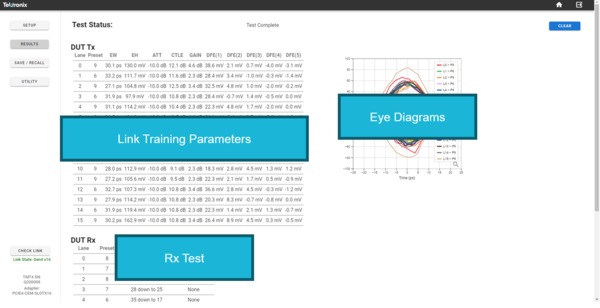
- DUT transmitter (Tx) eye diagrams and link training parameters for each lane tested
- DUT functional receiver (Rx) evaluation for each lane tested
- LTSSM Monitoring
- Receiver DUT Test beyond standard presets

Adapters and cables to address a wide range of PCIe devices
The TMT4 Margin Tester platform supports 13 standard PCIe adapters for testing system boards and add-in cards. This allows users to test a wide range of possible DUTs and allows evaluation of most common PC components, such as motherboards, graphics cards and SSDs; a straightforward way to link to and test PCIe devices.
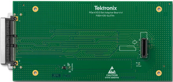
All adapters, aside from the M.2 and E1 edge, which have an integrated cable to accommodate specific loss conditions, can be interchanged easily with the use of the standard 16-lane high density cable. This gives users the flexibility to switch between PCIe form factors in seconds and minimizes downtime between tests.
Testing the signal path of DUT transmitters has never been easier
The DUT Transmitter (Tx) tests are optimized to deliver insight into the transmitter path performance of the DUT in minutes. For engineers today, evaluating the full link width Tx performance of their DUT can often take days or even weeks to perform. With the TMT4 Margin Tester, a high level link health evaluation of a Gen 4 device can be completed in as little as two minutes.
This test provides users a fast look at the eye diagrams of the link formed between the Margin Tester and the DUT and displays the associated link training parameters used to open the eye. This information enables teams to conduct more regular performance checks of the link and to quickly identify gross errors for any lane and preset combination.
This is especially useful for design and validation engineers who are often bottlenecked by the testing times of traditional oscilloscope and BERT testing equipment. For example, if engineers want to quickly see the effects of a BIOS change on the health of the link, they can scan the DUT, update the BIOS, scan the DUT again, and in minutes be able to evaluate the effect those changes had on the link performance.
Eye diagrams faster than ever before
As part of the DUT Tx tests, the user is shown eye diagrams for each lane and preset combination that represent the error-free region of the link formed between the DUT and the Margin Tester.
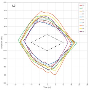
The major benefit of the Margin Tester is the speed at which a user can generate these eye diagrams. Since the eyes are shown to the user in real-time, it only takes seconds before results are displayed. This speed leads to dramatically reduced time to insights into DUT link health. With time to market pressures rising for engineers, Margin Tester steps up to provide insights to design and validation teams faster than ever before.
Link equalization parameters: Eye diagrams are not always the full story
The Margin Tester shows not only the performance of the link by displaying eye diagrams, but also displays how the Margin Tester’s receivers were adjusted to maximize the generated eye. Having both pieces of information is critical to understanding performance, as some eyes may need especially high levels of equalization in order to form the link. In the table displayed to the user, the Margin Tester shows the Attenuation, VGA (Gain), CTLE, and 5 DFE taps values used to maximize the eye opening. With this, the user can quickly see how much equalization is needed for each displayed eye diagram. The possible range of values for each of these equalization settings is shown in the following tables.
| Equalization | Number of possible settings | Range |
|---|---|---|
| ATT | 8 | -10.0 dB to -2.0 dB |
| VGA | 15 | 0.0 dB to +8.0 dB |
| CTLE | 32 | +2.0 dB to +15.0 dB |
| DFE Tap 1 | 256 | -55.0 mV to +55.0 mV (TYP1) |
| DFE Tap 2 | 128 | -44.0 mV to +43.3 mV |
| DFE Tap 3 | 128 | -22.0 mV to +21.7 mV |
| DFE Tap 4 | 128 | -16.0 mV to +15.8 mV |
| DFE Tap 5 | 128 | -11.0 mV to +10.8 mV |
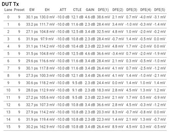
Having these settings visible enables engineers to not only get a quick glimpse of the performance of their link with eye diagrams, but also allows them to dig a layer deeper to understand the equalization used to open the eye. If an eye is wide open, but the equalization settings were pushed to their maximum, it may indicate there are some performance considerations for that given lane and preset combination. Eye diagrams on their own are not always the full story.
Enhanced DUT receiver testing: Receiver performance beyond presets
The DUT receiver (Rx) testing feature is a functional evaluation of the DUT’s receiver path. The test aims to determine how far the transmitted signal from the Margin Tester can be decreased, within a range of operation, before errors are returned. This enables engineers to easily evaluate functional Rx link health performance in as little as 30 seconds, saving valuable time and effort compared to existing equipment.
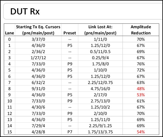
This quick test consists of a link train between the Margin Tester and DUT, where the DUT selects the presets for communication. The Margin Tester then steps down the transmitted amplitude by dropping the main cursor value by lane/preset, within an expected range of operation.
With this approach, a user can get a high-level evaluation of their Rx performance in less than a minute and determine if there are any problem lanes that may be worth investigating further with other equipment. If no errors are indicated, this is considered a functional pass. If errors are seen, the main cursor value where the error occurred is displayed to the user, and the test is considered a functional fail.
The receiver DUT is allowed to request the TMT4 transmitter, on any and all lanes, any valid combination of cursor coefficients. This means that TMT4 margin tester not only test standard presets but also test anything that the receiver under test requests.
When the receiver test is running, the TMT4 uses cursors to decrease the amplitude, but do not limit the test to a range. Instead, push the receivers as far as they will go until an error is registered, and report back both the main cursor value and % in amplitude reduction at point of failure. You can add a custom amplitude threshold value on the Custom Scan setup screen to assist in highlighting lanes that do not meet acceptance criteria.

Multiple scan options to choose from
The TMT4 offers two scan options: Quick Scan and Custom Scan. Both scan types include DUT Tx and DUT Rx tests and can be run from the same physical setup, but allow for different levels of control for the user. Each scan option has its own advantages.
An additional feature to the TMT4 Margin Tester is the use of the advanced Link Training Status State Machine (LTSSM) monitor. This advanced feature, together with the Quick and Custom Scan options, allow the user to identify anomalies in the Physical Layer interaction with the Data Link Layer according to PCIe State Machine descriptions.
Quick Scans: The fastest option for link health evaluation
The Quick Scan was developed to be the fastest option with minimal ability for the user to control specific parameters of the test. The intention is to provide results on how the link between the DUT and the Margin Tester performs after a natural link training to the specified speed and the maximum width of the DUT; up to Gen 4 x16.
This test offers the ability to do more frequent evaluation of link health after a natural link negotiation throughout the design process, to see general trends as physical layer, firmware, and BIOS settings are changed over time. Results include eye diagrams from each lane trained to the negotiated preset, the associated link training parameters, and the functional Rx test all within a few minutes. This offers users the ability to evaluate the health of the link their DUT forms with TMT4 faster than it often takes to even set up traditional testing equipment.
Approx. test time @ Gen 4 x16 links: 2-4 min.
Custom Scans: The comprehensive option for link health evaluation
The Custom Scan offers users much more flexibility in terms of testing and enables users to force specific test parameters to do more thorough evaluations of their Tx signal paths. In Custom Scan, users are able to select:
- Generation (PCIe Gen 3 or Gen 4)
- Lanes (Within the specified link width)
- Presets (Preset 0 – Preset 9)
- Clock Settings (SSC or SRIS)
- Pass/Fail Limits (User-specified)
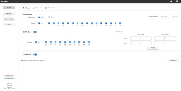
Custom scan is intended to be used when there is deeper investigation into specific lane-preset combinations needed or when a more comprehensive test of all lanes and presets is desired. Users can specify their own pass-fail limits and the Margin Tester will flag any results that fall outside these specified limits.
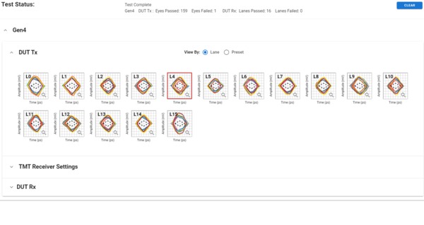
The results for Custom Scans appear different than for Quick Scans. In Custom Scan, a tiered results structure allows data to be expanded and collapsed based on the generation tested or by the type of test in a specified generation. Both the Tx eye diagram and the link training parameter table results can be configured to view the results by lanes tested or by presets tested. This enables users to quickly view results across all charts and draw conclusions as to the performance of any given lane or preset grouping for up to 160 lane-preset combinations in under 30 minutes.
Approx. test time @ Gen 4 x16 all lanes/presets: 25-30 min.
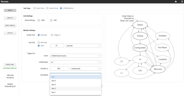
LTSSM monitoring
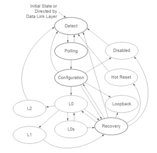
The state of the PCIe link is defined by a Link Training and Status State Machine (LTSSM). The LTSSM monitor provides information about the various states that the TMT4 Margin Tester experiences as a result of its interaction with the DUT, without regard to its role as a Root Complex (RC) or End Point (EP).
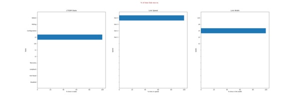
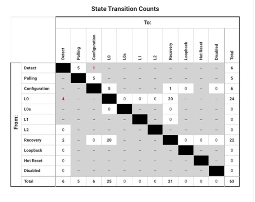
LTSSM Monitoring can be initiated manually or in the presence of a valid hardware Trigger in the signal. Additionally, a Trigger out signal can be generated on the occurrence of a selected event associated with a LTSSM state. Whenever performing LTSSM monitoring tests, the TMT4 results window displays the percentage of time that the link was seen in each of the LTSSM states and the transitions from one state to another using the LTSSM map.
Sub-state information
The LTSSM Setup window shows a graphical representation of the State Machine diagram for PCIe devices. Sub-state information is available for the Detect, Polling, Configuration, and Recovery states. To access the sub-state information, do the following.
- Hover over the desired LTSSM Major State.
- Click the chosen state to display the sub-state information.
- Click the Back button to return to the main LTSSM states diagram.
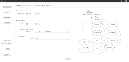
Setup and run LTSSM Monitor test
To configure and run the LTSSM Monitor Test in the Web UI, do the following.
Select Setup and then click the option next to LTSSM Monitor.

- Select the appropriate clock setting under Link Settings.
- You can select a manual start/stop or a triggered start for the test.
Select Manually to allow for test start when you click the Go button at the bottom of the screen.
Test stop will be set to occur when you click the Stop button.
Select Trigger In to allow for test start from an externally provided hardware trigger. The Trigger In becomes active on a HIGH to LOW transition. (See the TMT4 Specifications and Performance Verification Technical Reference on tek.com for further trigger information.)
Select After and set a specified amount of time in seconds, minutes, or hours after trigeer start to stop the test.
Trigger Out: If no trigger out signal is required, select None.
Any other selection will generate a trigger out hardware signal when one of the following valid test conditions is selected.
- State Entry or Exit: select one of 11 available States.
- State Transition: Select a From State and a To State.
- State Duration: Select the minimum time to satisfy the condition.
- Link Speed: This menu item appears for all of the above conditions except None. Select Any or the desired link speed.
Time for completion of a LTSSM test includes the user selected test time (for example, 10 s) plus additional processing time that is required for the data to be collected and compiled, such that the overall elapsed time can be a few seconds longer than the actual test.
LTSSM Monitor test results
Select the Results button to view the test results. In the Results window, you can view the % of time the link was in specific states and the count of state transitions.
The maximum test time of LTSSM events is limited to 6.5 hours.
Use the Save/Recall button in the left panel to save or recall files.
Save and recall results easily
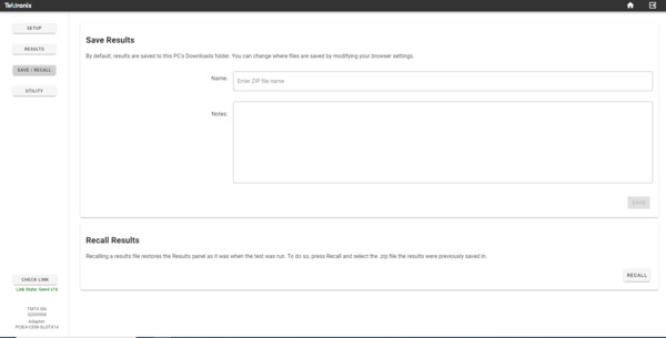
Results from any scan can be saved to a .zip file quickly and easily. All tabular data, like link training parameters and raw eye diagram measurements, are saved as .csv files and eye diagram images are saved as .png files.
Range of user interface options
The TMT4 Margin Tester can be controlled via three separate user interfaces: the Front Panel UI, the Web Browser UI, or the REST API. The Web Browser and REST API both enable users to control the instrument remotely.
Front Panel UI: Get to testing quickly
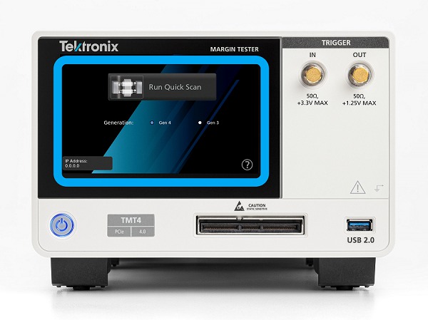
The front panel user interface is intended for quick use only and offers the ability to run Quick Scans, review the results, export the data, and access the IP address of the unit. For the ability to run Custom Scans, the user must use the web browser user interface or the programmatic interface via the REST API.
Web Browser UI: Remote use and greater user control
The web-based browser interface is optimal for users who want more access to the capabilities of the Margin Tester than is available via the front panel. From this interface, the user can access Quick and Custom Scans, Save/Recall results, and Utility menus to see firmware revisions and export error logs; all from an intuitive, easy-to-use web-based UI.
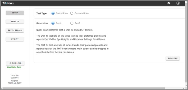
To access the web-based browser interface, the user must connect the Margin Tester via the Ethernet port located on the back of the instrument to either a local network or point-to-point to a PC. The Margin Tester has a dedicated IP address that is configured once connected to a local network or PC, allowing the user to connect to the UI by inputting the IP address shown on the Margin Tester into a supported web browser, which includes Google Chrome, Firefox, and Microsoft Edge.
Programmable REST API: Remote use and automation
The Margin Tester also supports programmatic control via the REST API. The API allow the user to select their programmatic language of choice and are ideal for engineers to use in automation applications.
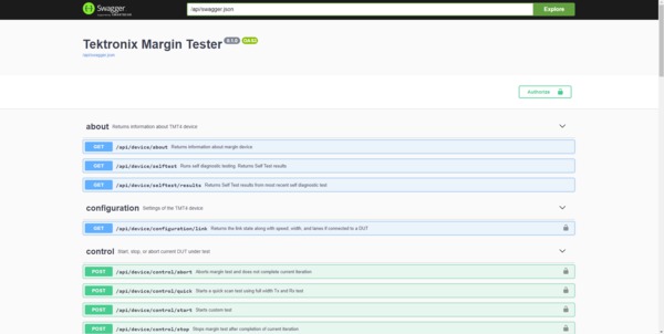
Documentation for how to use the REST API is available in the TMT4 Margin Tester User Manual.
DUT requirements
In order for the Margin Tester to successfully scan a DUT, there are a set of minimum requirements that the DUT must support. These include:
- The DUT must be capable of achieving an L0 state at Gen 3 (8 GT/s) and/or Gen 4 (16 GT/s) speeds.
- The DUT must be PCIe protocol aware and capable of handling a PERST (reset) signal.
- The link must be trained to at least x1 width.
- The selected lane to be tested must be within the current link width.
- The DUT must be capable of being forced into different Tx presets via protocol.
- The DUT must be able to return to L0 under its own control, without manual intervention.
- Add-in cards must support their own power beyond 75 W if required. The TMT4 supplies up to 75 W to AICs.
- End point DUTs must be configured as add-in cards, and root port DUTs must be configured as system boards.
- The DUT must select standard PCIe presets (0-9) from the Margin Tester to perform Rx tests.
Specifications
All specifications are typical unless noted otherwise. All specifications apply to all models unless noted otherwise.- PCIe generations supported
- Generations 3 and 4
- PCIe presets supported
- Presets 0 through 9
- PCIe adapters supported
Adapter2 Width DUT CEM Edge x1 System CEM Edge x4 System CEM Edge x8 System CEM Edge x16 System CEM Slot x16 Endpoint M.2 Edge3 x4 System M.2 Slot x4 Endpoint U.2 Edge x4 System U.2 Slot x4 Endpoint U.3 Edge x4 System U.3 Slot x4 Endpoint E1 Edge3 x4 System E1 Slot x4 Endpoint - Typical insertion loss
Insertion loss component4 At 4 GHz, typical At 8 GHz, typical TMT4 1.4 2.6 TMT4 cable 1.4 3 CEM Edge x1 0.5 1.5 CEM Edge x4 0.5 1.5 CEM Edge x8 0.5 1.5 CEM Edge x16 0.5 1.5 CEM Slot x16 7.1 13.5 M.2 Edge5 1.6 3.5 M.2 Slot 7.5 13.5 U.2 Edge 1.3 1.9 U.2 Slot 5.3 10 U.3 Edge 1.1 1.6 U.3 Slot 5.4 10 E1 Edge 1.7 2.7 E1 Slot 6 11.1 - Power source
- 240 W
- Physical characteristics
Dimension Including protective cover, handle, feet Without protective cover; including 50 Ω connectors Length 286 mm 277 mm Height 150 mm 147 mm Width 206 mm 200 mm - Environmental specifications
Attribute Specification Temperature Operating: 0°C to +50°C, with 15°C/hour maximum gradient, non-condensing.
Non-operating: -40°C to +71°C, with 30°C/hour maximum gradient.
Humidity Operating:
5% to 95% relative humidity (% RH) at up to +30°C,
5% to 75% RH above +30°C up to +40°C,
45% RH above +40°C up to 50°C, non-condensing.
Non-operating:
5% to 95% RH (Relative Humidity) at up to +30°C,
5% to 45% RH above +40°C up to +71°C, non-condensing.
Altitude Operating: Up to 3,000 meters, derate maximum operating temperature by 1°C per 300 meters above 1,500 meters altitude.
Non-operating: Up to 12,000 meters.
Mechanical shock Operating: Half-sine mechanical shocks, 50 g peak amplitude, 11 msec duration, 3 drops in each direction of each axis (18 total). (Military Standard MIL-PRF-28800F Class 3)
Ordering information
Use the following steps to select the appropriate instrument, adapters, and options for your needs.Step 1: Select instrument and adapters
| Model | Description |
|---|---|
| TMT4 | Tektronix Margin Tester for PCIe Gen 4 |
| PCIE4-CEM-EDGEX1 | PCIe 4.0 x1 CEM Edge Finger Adapter |
| PCIE4-CEM-EDGEX4 | PCIe 4.0 x4 CEM Edge Finger Adapter |
| PCIE4-CEM-EDGEX8 | PCIe 4.0 x8 CEM Edge Finger Adapter |
| PCIE4-CEM-EDGEX16 | PCIe 4.0 x16 CEM Edge Finger Adapter |
| PCIE4-CEM-SLOTX16 | PCIe 4.0 x16 CEM Slot Adapter |
| PCIE4-M2.22-EDGE | PCIe 4.0 M.2 22mm M-type Edge Finger Adapter and Cable |
| PCIE4-M2-SLOT | PCIe 4.0 M.2 M-type Slot Adapter |
| PCIE4-M2.22-EXTENDER | Five replacement extenders for PCI4-M2.22-EDGE adapter / cable |
| PCIE4-U2-EDGE | PCIe 4.0 U.2 Edge Finger Adapter |
| PCIE4-U2-SLOT | PCIe 4.0 U.2 Slot Adapter |
| PCIE4-U3-EDGE | PCIe 4.0 U.3 Edge Finger Adapter |
| PCIE4-U3-SLOT | PCIe 4.0 U.3 Slot Adapter |
| PCIE4-CABLE | Accessory cable for all PCIE4 adapters except PCIE4-M2.22-EDGE |
| PCIE4-ADAPTER-BAS | Accessory base to hold and stabilize slot adapters |
| PCIE4-PRO-BUNDLE | All PCIe 4.0 Adapters in a Hard Case |
| PCIE4-E1-EDGE | PCIe 4.0 E1 Edge Finger Adapter |
| PCIE4-E1-SLOT | PCIe 4.0 E1 Slot Adapter |
Step 2: Select power cord option
| Power cord option | Description |
|---|---|
| A0 | North America power plug (115 V, 60 Hz) |
| A1 | Universal Euro power plug (220 V, 50 Hz) |
| A2 | United Kingdom power plug (240 V, 50 Hz) |
| A3 | Australia power plug (240 V, 50 Hz) |
| A5 | Switzerland power plug (220 V, 50 Hz) |
| A6 | Japan power plug (100 V, 50/60 Hz) |
| A10 | China power plug (50 Hz) |
| A11 | India power plug (50 Hz) |
| A12 | Brazil power plug (60 Hz) |
| A99 | No power cord |
Step 3: Select service option
Protect your investment and your uptime with a service package for your TMT4.
Optimize the lifetime value of your purchase and lower your total cost of ownership with a calibration and extended warranty plan for your TMT4 Margin Tester. Plans range from standard warranty extensions covering parts, labor, and 2-day shipping to Total Product Protection with repair or replacement coverage from wear and tear, accidental damage, ESD or EOS. See the below table for specific service options available on the TMT4 product. Compare factory service plans https://www.tek.com/en/services/factory-service-plans.
Additionally, Tektronix is a leading accredited calibration services provider for all brands of electronic test and measurement equipment, servicing more than 140,000 models from 9,000 manufacturers. With 100+ labs worldwide, Tektronix serves as a global partner, delivering tailored whole-site calibration programs with OEM quality at a market price. View whole site calibration service capabilities https://www.tek.com/en/services/calibration-services.
| Service option | Description |
|---|---|
| T3 | Three Year Total Protection Plan. Includes repair or replacement coverage from wear and tear, accidental damage, ESD or EOS plus preventative maintenance. Including a 5 day turn-around time and priority access to customer support. |
| T5 | Five Year Total Protection Plan. Includes repair or replacement coverage from wear and tear, accidental damage, ESD or EOS plus preventative maintenance. Including a 5 day turn-around time and priority access to customer support. |
| R3 | Standard Warranty Extended to 3 Years. Covers parts, labor and 2-day shipping within the country. Guarantees faster repair time than without coverage. All repairs include calibration and updates. Hassle free - a single call starts the process. |
| R5 | Standard Warranty Extended to 5 Years. Covers parts, labor and 2-day shipping within country. Guarantees faster repair time than without coverage. All repairs include calibration and updates. Hassle free - a single call starts the process. |
| G3 | Three Year Gold Care Plan. Includes expedited repair of all product failures including ESD and EOS, access to a loaner product during repair or advanced exchange to reduce downtime, priority access to Customer Support, among others. |
| G5 | Five Year Gold Care Plan. Includes expedited repair of all product failures including ESD and EOS, access to a loaner product during repair or advanced exchange to reduce downtime, priority access to Customer Support, among others. |
| C3 | Calibration service 3 Years. Includes traceable calibration or functional verification where applicable, for recommended calibrations. Coverage includes the initial calibration plus 2 years calibration coverage. |
| C5 | Calibration service 3 Years. Includes traceable calibration or functional verification where applicable, for recommended calibrations. Coverage includes the initial calibration plus 4 years calibration coverage. |
1 DFE Tap 1 has a wide range of possible values, but will typically be within the stated range.
2 Signal path through adapters is designed to be lossy. See typical insertion loss table for details.
3 M.2 Edge adapter and E1 Edge adapter have their own integrated cable due to different loss constraints.
4 Typical Loss measurements have been captured from simulation, type testing, manufacturer's data, S21 in dB.
5 The M.2 Edge adapter does not use the TMT4 cable in its setup.
Tektronix is ISO 14001:2015 and ISO 9001:2015 certified by DEKRA. 55W-73966-2
