Contact us
Call us at
Available 9 AM - 5 PM IST Business Days
Download
Download Manuals, Datasheets, Software and more:
Feedback
High-voltage Differential Probes
TMDP0200 - THDP0200 - THDP0100 - P5200A - P5202A - P5205A - P5210A
More Information
- High Voltage Differential Probes
- Product Support
- Explore more Software models
Read Online:
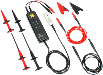
Tektronix offers a broad portfolio of high-voltage probing solutions that enable users to safely and accurately make floating measurements.
Key performance specifications
- Bandwidths up to 200 MHz
- Up to 6000 V differential (DC + pk AC)
- Up to 2300 V common (RMS)
Key features
- Overrange Indicator
- Safety Certified
- Switchable Attenuation
- Switchable bandwidth limit
Applications
- Floating measurements
- Switching power supply design
- Motor drive design
- Electronic ballast design
- CRT display design
- Power converter design and service
- Power device evaluation
Connectivity
- BNC interface (P5200A probes)
- TekVPI® interface (TMDP and THDP Series probes)
- TekProbe® interface (P5202A, P5205A, and P5210A Series probes)
Safe high-voltage probe solutions
The THDP0100 and P5210A have the largest differential dynamic range capability from Tektronix, allowing users to safely measure up to ±6000 V. The THDP0100 supports bandwidths up to 100 MHz and slew rates up to 2500 V/ns at 1/1000 gain. These probes are supplied with two sizes of hook tips and have an overrange visual and audible indicator which warns the user when they are exceeding the linear range of the probe.
The THDP0200 and P5205A are active differential probes that are capable of safely measuring differential voltages up to ±1500 V. The probes are effective in making measurements in IGBT circuits such as motor drives and power converters. The THDP0200 supports bandwidths up to 200 MHz and slew rates up to 275 V/ns at 1/250 gain.
The TMDP0200 and P5202A are designed for medium-voltage applications with differential requirements up to ±750 V. These probes have lower attenuation ranges and offer better signal-to-noise ratio.
The P5200A can be used with any oscilloscope and enables users to safely make measurements of floating circuits with their oscilloscope grounded. The P5200A Active Differential Probe converts floating signals to low-voltage ground-referenced signals that can be displayed safely and easily on any ground-referenced oscilloscope.
Connectivity options
The TMDP and THDP Series probes are equipped with the TekVPI® interface which allows smart communication between the oscilloscope and probe. Pushing the probe menu button will launch the probe control menu on the oscilloscope display providing access to all relevant probe settings and controls. These probes are designed to operate on TekVPI® oscilloscopes without requiring the TPA-BNC adapter.
The P52xxA Series probes are equipped with the Tektronix TekProbe® interface which communicates scale information to the oscilloscope. Direct connections can be made to oscilloscopes configured with the TekProbe® interface or to any oscilloscope when used with the 1103 TekProbe® Power Supply.
Specifications
All specifications are guaranteed unless noted otherwise. All specifications apply to all models unless noted otherwise.
Model Overview
TMDP0200 | THDP0200 | THDP0100 | |
---|---|---|---|
Attenuation | 25X / 250X | 50X / 500X | 100X / 1000X |
Differential Voltage (Typical) | 250X: ±750 V | 500X: ±1500 V | 1000X: ±6000 V |
25X: ±75 V | 50X: ±150 V | 100X: ±600 V | |
Common Mode Voltage (Typical) | ±750 V | ±1500 V | ±6000 V |
Maximum Input Voltage-to-Earth (Typical) | 450 V CAT I | 1000 V CAT II | 2300 V CAT I |
300 V CAT III | 600 V CAT III | 1000 V CAT III | |
Bandwidth (Typical) | 200 MHz | 200 MHz | 100 MHz |
Rise Time | <2 ns | <2 ns | <3.6 ns |
Slew Rate (Typical) | <275 V/ns at 1/250 gain | <650 V/ns at 1/500 gain | <2500 V/ns at 1/1000 gain |
Input Impedance at the Probe Tip (Typical) | 5 MΩ || <2 pF | 10 MΩ || <2 pF | 40 MΩ || <2.5 pF |
Typical CMRR (Typical) | DC: > 80 dB | DC: > 80 dB | DC: > 80 dB |
100 kHz: > 60 dB | 100 kHz: > 60 dB | 100 kHz: > 60 dB | |
3.2 MHz: > 30 dB | 3.2 MHz: > 30 dB | 3.2 MHz: > 30 dB | |
100 MHz: > 26 dB | 100 MHz: > 26 dB | 100 MHz: > 26 dB | |
Cable Length (Typical) | 1.5 m | 1.5 m | 1.5 m |
DC Gain Accuracy | ±2% | ±2% | ±2% |
P5200A | P5202A | P5205A | P5210A | |
---|---|---|---|---|
Attenuation | 50X / 500X | 20X / 200X | 50X / 500X | 100X / 1000X |
Differential Voltage (Typical) | 500X: ±1300 V | 200X: ±640 V | 500X: ±1300 V | 1000X: ±5600 V |
50X: ±130 V | 20X: ±64 V | 50X: ±130 V | 100X: ±560 V | |
Common Mode Voltage (Typical) | ±1300 V | ±640 V | ±1300 V | ±5600 V |
Maximum Input Voltage-to-Earth (Typical) | 1000 V CAT II | 450 V CAT l | 1000 V CAT II | 2300 V CAT l |
300 V CAT ll | 1000 V CAT III | |||
Bandwidth (Typical) | 50 MHz | 100 MHz | 100 MHz | 50 MHz |
Differential Input Impedance (Typical) | 10 MΩ || 2 pF | 5 MΩ || 2 pF | 10 MΩ || 2 pF | 40 MΩ || 2.5 pF |
Input Impedance between each Input and Ground (Typical) | 5 MΩ || 4 pF | 2.5 MΩ || 4 pF | 5 MΩ || 4 pF | 20 MΩ || 5 pF |
Typical CMRR (Typical) | DC: >80 dB | DC: >80 dB | ||
100 kHz: >60 dB | 100 kHz: >60 dB | |||
3.2 MHz: >30 dB | 3.2 MHz: >40 dB | |||
50 MHz: >26 dB | 50 MHz: >30 dB | |||
Cable length (Typical) | 1.5 m | |||
DC Gain Accuracy | ±2% | ±2% | ±2% | ±2% |
THDP0200 probe label
1. The differential voltages the maximum measurable range between the (+) and (-) input leads of the probe. Beyond these limits, the output could be clipped.
2. The maximum common mode voltage and maximum input voltage-to-earth (RMS) are the maximum voltages that each input lead (+/-) can be from ground.
Ordering information
Use the following information to choose accessories and options for your probes.
Standard accessories
P5200A, P5202A, and P5205A
Description | Quantity included | Reorder part number |
---|---|---|
Hook clips | 1 set of red and black hook clips | AC280-FL |
Pincer clips | 1 set of red and black pincer clips | AC283-FL |
Alligator clips | 1 set of red and black alligator clips | AC285-FL |
Extension cables | 1 set of red and black extension cables | 196-3523-00 |
TMDP0200 and THDP0200
Description | Quantity included | Reorder part number |
---|---|---|
Hook clips | 2 | AC280-FL |
Pincer clips | 2 | AC283-FL |
Alligator clips | 2 | AC285-FL |
Extension cables | 2 | 196-3523-00 |
Test leads | 2 | TP175 (must be ordered through Fluke). |
Probe holder | 1 | TPH1000 |
THDP0100 and P5210A
Description | Quantity included | Reorder kit part number |
---|---|---|
Probe tips | 2 | 020-3070-00 |
Large hook clips | 2 | |
Small hook clips | 2 |
Probe and accessory derating table
Common mode, relative to ground, when used with P52xxA Series probes
Accessory | Description | TMDP0200 / P5202A | THDP0200 / P5200A / P5205A | THDP0100 / P5210A |
---|---|---|---|---|
450 V CAT I | 1000 V CAT II | 2300 V CAT I | ||
300 V CAT II | 600 V CAT III | 1000 V CAT III | ||
196-3523-00 | 2x Extender Leads (1.5 m) | Standard | Standard | Standard |
2300 V CAT I | 450 V CAT I | 1000 V CAT II | 2300 V CAT I | |
1000 V CAT III | 300 V CAT II | 600 V CAT III | 1000 V CAT III | |
AC280-FL | 2x Hook Clips | Standard | Standard | Optional |
1000 V CAT III | 450 V CAT I | 1000 V CAT II | 1000 V CAT I | |
600 V CAT IV | 300 V CAT II | 600 V CAT III | 1000 V CAT III | |
AC283-FL | 2x Pincer Clips | Standard | Standard | Optional |
1000 V CAT III | 450 V CAT I | 1000 V CAT II | 1000 V CAT I | |
600 V CAT IV | 300 V CAT II | 600 V CAT III | 1000 V CAT III | |
AC285-FL | 2x Alligator Clips | Standard | Standard | Optional |
To prevent damage to the insulation on the AC285-FL alligator clips, do not use in high A/m magnetic fields at high frequencies, which can cause induction heating of the jaws. | 1000 V CAT III | 450 V CAT I | 1000 V CAT II | 1000 V CAT I |
600 V CAT IV | 300 V CAT II | 600 V CAT III | 1000 V CAT III | |
020-3070-00 | Hook Clip Kit | Optional | Optional | Standard |
2300 V CAT I | 450 V CAT I | 1000 V CAT II | 2300 V CAT I | |
1000 V CAT II | 300 V CAT II | 600 V CAT II | 1000 V CAT II | |
TP175 | 2x Test Leads | Standard (TMDP0200) | Standard (THDP0200) | Optional |
1000 V CAT III | 550 V CAT I | 1000 V CAT II | 2300 V CAT I | |
600 V CAT IV | 300 V CAT III | 600 V CAT III | 1000 V CAT III |
Options
Power plug options (P5200A only)
- Opt. A0
- North America power plug (115 V, 60 Hz)
- Opt. A1
- Universal Euro power plug (220 V, 50 Hz)
- Opt. A2
- United Kingdom power plug (240 V, 50 Hz)
- Opt. A3
- Australia power plug (240 V, 50 Hz)
- Opt. A4
- North America power plug (240 V, 50 Hz)
- Opt. A5
- Switzerland power plug (220 V, 50 Hz)
- Opt. A6
- Japan power plug (100 V, 50/60 Hz)
- Opt. A10
- China power plug (50 Hz)
- Opt. A11
- India power plug (50 Hz)
- Opt. A12
- Brazil power plug (60 Hz)
- Opt. A99
- No power cord
Service options
- Opt. C3
- Calibration Service 3 Years
- Opt. C5
- Calibration Service 5 Years
- Opt. D1
- Calibration Data Report
- Opt. D3
- Calibration Data Report 3 Years (with Opt. C3)
- Opt. D5
- Calibration Data Report 5 Years (with Opt. C5)
- Opt. R3
- Repair Service 3 Years (including warranty)
- Opt. R5
- Repair Service 5 Years (including warranty)
- Opt. SILV200
- Standard warranty extended to 5 years
Probes and accessories are not covered by the oscilloscope warranty and Service Offerings. Refer to the datasheet of each probe and accessory model for its unique warranty and calibration terms.