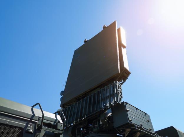
Radar applications today, whether found in defense or in aerospace, increasingly require analysis across multiple channels. For AESA antenna, transmitter and receiver module calibration both synchronization and wide bandwidth capture is important and being able to synchronize multiple channels for efficient calibration can be challenging.
Radar DSP and system integrator engineers working in FPGA, ASICs, as well as other silicon-on-chip (SOC) designs need to replicate and generate realistic electronic warfare (EW) scenarios. They need to be able to analyze both the radar as well as the target simulator under test. This also involves beamformer processing, doppler filtering, and pulse compression stages for doing more advanced analysis of radar.
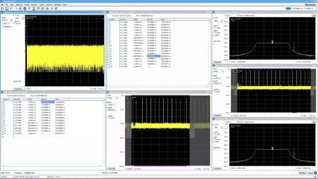
Tools that make this possible include Tektronix spectrum analyzers or oscilloscopes together with Tektronix SignalVu VSA or vector signal analysis software. The latter offers a comprehensive and consistent look and feel across a number of hardware instruments. It's also a multi-domain tool set for spectrum analysis, vector signal analysis, as well as demodulation of signals in addition to more advanced things like pulse analysis.
Scenario Generation and Analysis Challenges Faced by Radar/EW System Engineers
One way to think about tackling scenarios and challenges is to explore automated pulse parameter analysis on each channel of the oscilloscope. In a typical radar test system scenario, you have both the radar under test and at the same time it’s attached to a radar target simulator. The challenge this presents is being able to measure group delay of this entire system, which could affect the range simulation. The radar target simulator applies some amount of delay, or doppler shift, to simulate position and velocity. So characterizing that delay or shift is needed in order to ensure that the simulator is operating as it should.
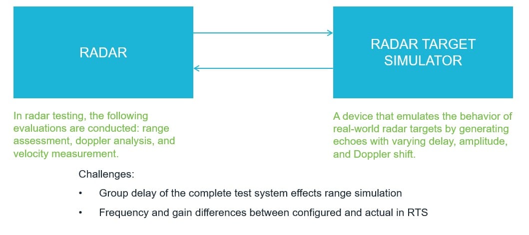
Figure 1. Radar Test System
Frequency and gain differences could cause errors and there are a number of sources for timing errors as well. We need to assign, or we need to probe, each of the outputs of the radar and the outputs of the target simulator to be able to see the before and after state of our signal. With a multi-channel oscilloscope we can easily look at both the before and after of our radar target simulator. The below image represents what our setup looks like.
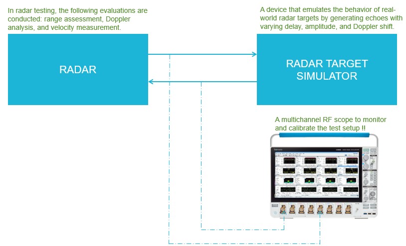
Figure 2. Radar Test System with Oscilloscope and Spectrum Analysis Software.
Watch a demonstration showing how a radar and its target simulator can be calibrated and verified using multi-channel SignalVu software running on the 6 Series B MSO oscilloscope.