Introduction to Power Supply Specifications
At first glance, a variable DC power supply appears to be a fairly simple device. However, it is a sophisticated, accurate, electrically-rugged workhorse. It must reliably deliver voltage and current that is stable, precise, and clean, no matter its load resistive, inductive, capacitive, low impedance, high impedance, steady-state, or variable. How well the power supply fulfills this mission and where it reaches its limits are defined in its specifications. Choosing the right power supply for your application requires a good understanding of power supply specifications.
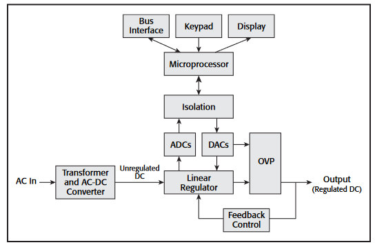
The following describes specifications for linear power supplies. Linear power supplies are durable and accurate and deliver power with low noise. Their simple, direct feedback mechanisms provide excellent load regulation and overall stability. Figure 1 shows a simplified block diagram of a linear power supply.
Linear Power Supply Specifications
It may seem like there are a multitude of specifications for linear power supplies, but they can be grouped into three logical categories: accuracy and resolution, stability, and AC characteristics. We will describe the key specifications that fall into each of these groups.
Most DC power supplies have two modes of operation. In Constant Voltage (CV) mode, the power supply regulates the output voltage based on the user settings. In Constant Current (CC) mode, the power supply regulates the current. Whether the power supply is in CV or CC mode depends not only on the user settings, but also on the resistance of the load. A power supply has different specifications that apply when it is in CV mode and when it is in CC mode.
Accuracy and Resolution
At any given time, either voltage or current is being regulated by the power supply and matches the setting within the instrument's accuracy.
- In CV mode, the output voltage matches the voltage setting within the accuracy specifications of the instrument. The current is determined by the impedance of the load.
- In CC mode, the output current matches the current limit setting. The voltage is determined by the impedance of the load.
Historically, the DC power supply user turned to potentiometers to set output voltage or current. Today, microprocessors receive input from the user interface or from a remote interface. A digital-to-analog converter (DAC) takes the digital setting and translates this into an analog value that is used as the reference for the analog regulator. The setting resolution and accuracy values are determined by the quality of this conversion and regulation process.
Voltage and current settings (sometimes called limits or programmed values) each have resolution and accuracy specifications associated with them. The resolution of these settings determines the minimum increment at which the output can be adjusted, and the accuracy describes the extent to which the value of the output matches international standards. Setting and read back specifications should be considered separately.Good performance on readback accuracy does not necessarily mean good performance in setting accuracy.
Most DC power supplies provide built-in meters for measuring both voltage and current. The meters measure the voltage and current being delivered by the power supply output.Since the meters read the voltage and current back into the power supply, the measurements produced by the meters are often called readback values. Most professional power supplies incorporate digital meters that use analog-to-digital converters;and, for these internal instruments, the specifications are similar to those of a digital multimeter. The power supply displays meter values on its front panel and can also transmit them over its remote interface, if it is equipped with one.
Setting Accuracy
Setting accuracy determines how close the regulated parameter is to its theoretical value as defined by an international standard.Output uncertainty in a power supply is largely due to error terms in the DAC, including quantization error. Setting accuracy is tested by measuring the regulated variable with a traceable, precision measurement system connected to the output of the power supply. Setting accuracy is given as:
±(% of setting + offset)
For example, the Keithley 2200-32-3 power supply has a voltage setting accuracy specification of ±(0.03% + 3mV).Therefore, when it is set to deliver 5V, the uncertainty in the output value is (5V)(0.0003 + 3mV), or 4.5mV. Current setting accuracy is specified and calculated similarly.
are often called readback values. Most professional power supplies incorporate digital meters that use analog-to-digital converters;and, for these internal instruments, the specifications are similar to those of a digital multimeter. The power supply displays meter values on its front panel and can also transmit them over its remote interface, if it is equipped with one.
Setting Resolution
Setting resolution is the smallest change in voltage or current settings that can be selected on the power supply. This parameter is sometimes called programming resolution. The resolution specification limits the number of discrete levels that can be set. Often, this is defined by a combination of user interface digits available and the number of bits available in the DAC. A DAC with more bits has finer control of its output and is able to deliver more distinct values for the control loop to use as a reference. However, with corrections for offset and gain errors,there will be less resolution than the number of bits in the DAC would suggest.
Changing a setting in a single step of resolution may not always cause a corresponding change in the output. However, the setting accuracy specification governs the relationship between settings and output, and a calibrated instrument should perform within this tolerance.
Setting resolution may be expressed as an absolute unit value or as a percentage of full scale. For example, the voltage setting resolution on the Keithley 2200-32-3 is 1mV and the current setting resolution is 0.1mA.
Readback Accuracy
Readback accuracy is sometimes called meter accuracy. It determines how close the internally measured values are to the theoretical value of the output voltage (after setting accuracy is applied). Like a digital multimeter, this is tested using a traceable reference standard. Readback accuracy is expressed as:
±(% of measured value + offset)
Readback Resolution
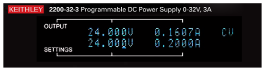
Readback resolution is the smallest change in internally measured output voltage or current that the power supply can discern. It is usually expressed as an absolute value, but may also be given as a percentage of full scale. The voltage readback resolution on the Keithley 2200-32-3 is 1mV and the current readback resolution is 0.1mA. See Figure 2
Using Remote Sense for Better Voltage Accuracy
Voltage drop in cables that carry current between the power supply and device under test (DUT) means that the voltage at the DUT is less than the voltage at the output terminals of the power supply. Using heavier-gauge wire reduces the voltage drop in the test leads on any power supply. Keeping cables as short as possible also helps. If a power supply is equipped with remote sense capability, using a four-wire connection can help make sure that the voltage you set on the power supply is the voltage you get at the DUT.
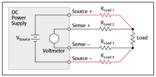
With a four-wire connection from the power supply to the DUT, one set of leads carries the output current while the other set of leads is used by the power supply to measure voltage directly at the DUT terminals, as illustrated in Figure 3. The sense leads are connected inside the power supply to a high impedance voltmeter circuit; therefore, close to zero current is flowing in the sense leads, virtually eliminating voltage drop in those leads. The power supply maintains the desired output voltage at the sense leads by increasing the voltage at the output to compensate for voltage drops in the source leads that deliver the current to the DUT.
Stability Specifications
Stability specifications describe how a power supply responds to changes. Several specifications state the instrument's ability to deliver stable output over the short term. This section discusses specifications that describe output stability under conditions of changing load, AC line voltage, and temperature.
Over the long term, the performance of a power supply inevitably changes due to aging. Long term stability issues are managed by requiring regular verification and calibration of the instruments. Keithley power supplies have a one-year calibration cycle.
Temperature Stability
The accuracies discussed above are usually specified as being valid over a particular range around 25°C. A typical range is between 20°C and 30°C (68°F to 86°F). If you are using the power supply in a laboratory environment with stable ambient temperature, then the effect of temperature on the output should be small. If, on the other hand, you are working in an industrial setting or field installation that may experience temperatures significantly different from room temperature, it is important to consider this in determining accuracy. The uncertainty in the output increases as ambient temperature deviates from room temperature.
Load Regulation (Voltage and Current)
Load regulation is a measure of the ability of an output channel to remain constant during changes in the load. See Figure 4.As the impedance of the DUT changes, the regulated parameter should not change significantly. Of course, if the load changes too much, the regulated parameter may change between voltage and current, depending on the limit setting for the unregulated parameter. Assuming the power supply does not reach this crossover point, it maintains a low output impedance when operating as a voltage source and a high output impedance when operating as a current source.

Load regulation may be specified in several ways. For example, voltage regulation may be expressed as voltage change per ampere drawn. However, most power supply manufacturers, including Keithley, express load regulation as output accuracy during a significant change in the unregulated parameter.This familiar format is easy to understand and easy to verify through testing:
±(% of setting + offset)
Keithley load regulation specifications are verified with the regulated variable set to full scale output. The unregulated variable is varied from 0 to 98%, and the output is checked against the relevant specification.
Using the Keithley 2200-32-3 power supply as an example,the load regulation specification for output voltage is ±0.01% of the selected output voltage +2mV, so at its full rated output of 32V, the output remains within ±5.2mV even as the load changes from drawing no current to just below 3A, which is the instrument's maximum rated current.
Load regulation for CC mode is defined similarly to load regulation for CV mode. Current load regulation describes how the power supply output current varies in response to a step change in load impedance
Line Regulation (Voltage and Current)
Line regulation is a measure of the ability of the power supply to maintain its output voltage or output current while its AC line input voltage and frequency vary over the full allowable range.Line voltage and frequency greatly affect the available power to feed the output, especially when maximum current is being drawn from the supply.
Line regulation can be ignored in a lab with stable AC load voltage when testing for short periods of time. However, if you are working in an area prone to sags and swells in AC line voltage or are testing over extended periods, line regulation is an important consideration.
Voltage line regulation can be specified as a ratio of the DC output voltage change to the change in AC line (RMS) voltage and frequency. However, to be consistent with most test equipment specifications, manufacturers usually express line regulation as an uncertainty in the output over the range of acceptable AC line parameters. This offers a worst case picture and is given as:
±(% of setting + offset)
For example, the Keithley 2200-32-3 has a voltage line regulation specification of ±(0.01% + 1mV). Therefore, when it is set to deliver 32VDC, the output remains within (32V)(0.01% +1mV) = 4.2mV even as the AC source voltage varies over the full allowable range.
Current load regulation is a comparable specification. Instead of stating the allowable voltage variation in the output as the AC source varies, it states the amount of allowable current variation as the AC source varies. This specification is typically valid over the allowable range of the AC source voltage and frequency.
AC Characteristics
Although we are discussing DC power supplies, the output of these power supplies is not perfect DC. Some AC is to be expected on the output. For some applications, high AC on the output can produce unexpected circuit behavior, so it helps to know the amplitude of the residual AC. In addition to AC noise, it may be useful to know the transient response of the power supply to changes in load and settings. For example,in automated testing, it is important to know when the power supply is settled in response to a change in settings.
Ripple and Noise Specifications
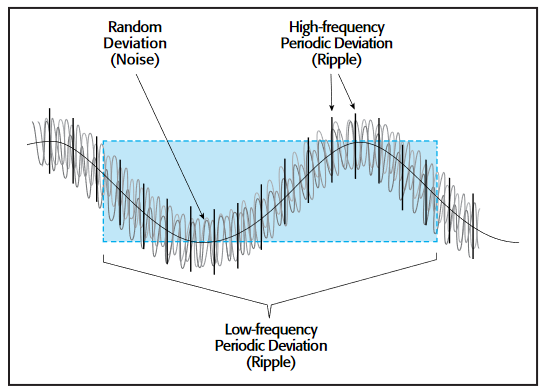
Spurious AC components on the output of a DC supply are called ripple and noise, or periodic and random deviation (PARD). These terms are often used interchangeably. The term ripple refers to periodic AC on the output. When viewed in the frequency domain, ripple shows up as spurious responses.Unlike ripple, which is periodic, noise is random. Noise covers a broad spectrum and when viewed in the frequency domain, it manifests itself as an increase in the baseline. See Figures 5 and 6. Since ripple and noise are usually lumped together and cannot be easily separated from each other, in this application note we will use the acronym PARD to refer to the combined effects.
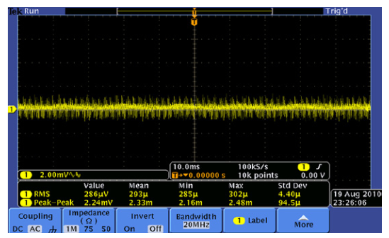
PARD specifications must be specified with a bandwidth and should be specified for both current and voltage. Current PARD is relevant when using a power supply in CC mode, and it is often specified as an RMS value. Because the shape of PARD is indeterminate, voltage PARD is usually expressed both as a root mean square voltage, which can provide a sense of the noise power, and also as a peak-to-peak voltage, which may be relevant when driving high impedance loads.
Because of the bandwidth consideration, PARD specifications are heavily dependent upon the measurement technique used to test them. You can usually find the procedure for checking PARD in the manufacturer's performance verification procedure.It is important to consider the whole signal path used to verify ripple and noise specifications. For example, using a high bandwidth oscilloscope with a low bandwidth probe can make the specifications appear better than they are. The voltage PARD specifications of the Keithley 2200-32-3 illustrate this. The voltage PARD specification is 1mVRMS and 4mVP-P over a bandwidth of 20Hz to 7MHz. A wider bandwidth specification is also given for frequencies from 20Hz to 20MHz. This specification is 3mVRMS and 20mVP-P.
Transient Response
Another set of AC characteristics describes how quickly a power supply can respond to changes. Transient response specifications indicate how quickly the output settles to a stable DC value after a change in load or settings. Most power supplies have a large capacitance in parallel with their outputs to help deliver clean,steady DC. When this capacitance is placed in parallel with the load resistance, a time constant results and the size of the time constant varies with the load impedance. Because of the heavy dependence on the resistance of the load, response to setting changes must be specified for a specific load. It is common to see specifications for open circuits, short circuits, or specific resistance values.
Transient response is tested by applying significant step changes to load impedance and power supply settings, and measuring the time to settle to a final value. The voltage transient response for all Keithley Series 2200 power supplies is given for three conditions: increasing load, increasing setting,and decreasing setting.
| Time to stabilize to within 75mV of terminal value | |
| Load change from 0.1A to 1A | <400μs |
| Setting change from 1V to 11V into a 10Ω load | <35ms |
| Setting change from 11V to 1V into a 10Ω load | <35ms |
Accurate Results Require an Accurate Power Supply
To ensure confidence in your test results and the repeatability of those results, you must have a power supply that can accurately deliver the power you need to your DUT. If your power supply does not have high enough accuracy or stability,your measurement results will be affected by both your DUT's performance and the performance of your power supply.Temperature drift, sudden load changes, and fluctuating AC line voltage are just some of the factors that can cause trouble.An accurate power supply that is designed to cope with these variations and to consistently and accurately provide the voltage or current you specify will allow you to be confident in your test results.
Additional Performance Considerations
All aspects of a product are not typically specified, otherwise products would never reach the market in a cost-effective and timely manner. Also some aspects of a product's operation are more valuable features than specified performance. Even though features are not specified, it's necessary to be aware of them and understand what the features can offer. Obviously, not all power supplies have the same feature sets, nor are all features implemented in the same way. There are subtle differences in the features of different power supply vendor's products.
Isolated Outputs
Multiple channel power supplies can have output channels that are tied to a common point on their low side or they can be completely isolated. When the channels are connected with the same common point, they cannot be used to power circuits that are isolated from each other. Medical monitoring devices, for example, have circuits that are in direct contact with a human.Those circuits are on a common reference that is isolated from the circuitry on the power line side of the device. This is also true for a large number of products that use opto-isolators to create separate, independent common reference points for different analog circuits or analog and digital circuits. Testing the medical device circuits and other circuits with isolated references with a multi-channel power supply requires that the power supply channels be isolated. Determine your needs for either non-isolated or isolated channels and determine how the channels of a multi-channel power supply are configured before selecting a multi-channel power supply
Independent Control
In some cases battery-powered devices, for example, may contain circuits that can be turned off to maximize battery life. A cellular phone, for example, may turn off the RF power amplifier circuitry, the highest power consuming circuit in a cellular phone, to maximize battery life. If a multi-channel power supply is being used to power different circuits in a cellular phone, the flexibility to turn off a power supply channel without turning off all channels is essential when testing circuits that have their power supply controlled based on the state of the instrument. When investigating a multi-channel power supply,determine whether the capability to enable and disable channels individually is needed. If such a feature is required, make sure the power supply provides that capability.
Programmability of the Digital Channel
Triple channel power supplies typically have two analog channels (to power multiple circuits or to create bipolar power supplies for testing circuits that can output or measure both positive and negative signals) and a third channel that is intended to power a digital circuit. The voltage for this third circuit, the digital circuit,is typically 10V or under and most often it is around 5V or 6V for testing digital circuits operating at 5V or less. Pay attention to how the power supply vendor specifies that channel. Some products have fixed voltage output channels that cannot be programmed. Typically those are 5V channels. If you have digital circuitry that operates at 3.3V or 1.8V, you will want the third channel to be programmable.
Extending Range of a Multi-Channel Power Supply with Series and Parallel Operation
Often you may need more voltage or more current than an individual channel can provide. Some multi-channel power supplies can allow channels to be combined in series and in parallel to increase the output voltage and the output current.In some cases, a multi-channel supply may allow connecting two channels in series to increase voltage output, but combining channels in parallel will not be possible. This condition occurs if the two channels are not isolated and have a common low reference point. For full flexibility to get both increased voltage (typically double the voltage of one channel or double the current of one channel), select a multi-channel power supply with isolated output channels. The Keithley Model 2220-30-1 Dual Channel and 2230-30-1 Triple Channel Power Supplies include special operating display modes that configure the output display to directly show the combined output of the channels so that the exact output to the load is always shown even when the channels are configured in series or in parallel.
Testing a Bipolar Circuit Over its Operating Voltage Range using Tracking Functionality
It is critically important to ensure that a circuit operates within its performance specifications over the circuit's defined voltage operating range. A convenient way to test a bipolar circuit with a multi-channel power supply is have both channels, the positive output and the negative output, linked together so they change synchronously with each other. This is known as tracking. Some multi-channel power supplies can track only with each channel at the same voltage magnitude. Other power supplies, such as the the Keithley Model 2220-30-1 and 2230-30-1, allow tracking with a variable ratio between the two channels. Tracking is a valuable function for testing bipolar circuits. If you want this capability,make sure the multi-channel power supply that you select has the feature and determine whether you want simple tracking or more flexible tracking with a variable relationship between the voltage on the two channels.
Ensuring Your Power Supply is a Quality Instrument and Meets Its Specifications
To be confident that a power supply has been designed and manufactured with an appropriate level of quality, look for a clear explanation from the manufacturer of how it supports its published specifications. For example, the manufacturer should use test instruments that have been calibrated to standards traceable to a recognized primary standards laboratory. Also,look for a safety certification by one of the internationally recognized agencies, such as CSA, UL, or VDE. This says that the power supply manufacturer has had independent confirmation of compliance to international safety standards.
Regular performance verification is important to ensure that your power supply is operating within the manufacturer's specifications. For Keithley power supplies, the recommended calibration cycle is one year. Detailed descriptions of performance specifications and the procedures for verifying performance can be found in the documentation supplied with the power supply for each instrument. Many of these specifications are tested as part of the manufacturing process and as part of the performance verification that is conducted during routine maintenance. Keithley verifies every power supply using traceable standards and offers test data from quality testing as an option.
Find more valuable resources at TEK.COM
Copyright © Tektronix. All rights reserved. Tektronix products are covered by U.S. and foreign patents, issu ed and pending. Information in this publication supersedes that in all previously published material. Specification and price change privileges reserved. TEKTRONIX and TEK are registered trademarks of Tektronix, Inc. All other trade names referenced are the service marks, trademarks or registered trademarks of their respective companies.
9.14.12 3137f