In this post, we’ll be walking you the basics for checking the control logic of a power supply design.
This is arguably the most important and complex part of the design. In this stage, you will be testing for proper compensation, voltage, timing and frequency responses. Tasks include the following:
- Measuring the modulation signal at the switching device driver during power-on to verify proper switching frequency, pulse width and duty cycle at different loads
- Checking the loop frequency response by injecting a frequency sweep signal through a wideband injection transformer in the control loop
- Using a frequency response analyzer to measure the gain and phase of the circuit
At this point, it’s important to monitor input and output voltages as well as feedback or control signals. This will help to ensure that the loop response (e.g. critical damping) is what you expected during changes of input voltage and output load.
In order to verify the operation of circuits, such as soft start, short-circuit protection, shutdown and current fold-back, you will need to monitor the input and output voltages along with the control signals.
For digitally-controlled power supplies you will need to capture and display time-correlated views of the analog, digital and serial bus control signals. This will allow you to visualize the system operation and ensure that your system is working properly.
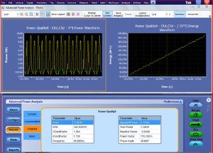
For these tasks, be sure to take a look at DPOPWR Advanced Power Measurement and Analysis software that effectively transforms a Tektronix Windows-based oscilloscope into a sophisticated debug and analysis tool. This software allows you to configure multiple measurements with custom defined settings. You can also measure and analyze power dissipation in switching devices and analyze magnetic parameters, all from a single acquisition.

Once you have thoroughly de-bugged your design’s control logic, it’s time to check the switching characteristics of the power stage. In the next post in this series, we’ll walk you through the steps on how to do just that. For more information on DPOPWR software go to: /node/50531
See More Power Supply Measurement Tips in this 10-part series:
Part 1: Component Selection and Characterization for Power Supply Design
Part 2: Low-Voltage DC Circuit Power-On Test
Part 3: High-Voltage AC Circuit Power-On Test
Part 4: Digital and Analog Control Circuit Debug
Part 5: Testing Power Stage Switching Characteristics
Part 6: Switching and Conduction Loss Testing
Part 7: Power Supply Specification Check
Part 8: Power Line Compliance Testing
Part 9: EMI Troubleshooting and Pre-compliance
Part 10: Design Validation