In this installment of our series on power supply testing from start to finish, we’ll walk you through the steps for testing the switching characteristics at no-load, nominal-load and full load conditions.
Before you begin, make sure that the turn-on, turn-off, duty-cycle and dead time of all switches, such as MOSFETs and IGBTs, are as expected. Tektronix oscilloscopes include a high resolution mode that essentially increases the vertical resolution so that turn-on and turn-off can be calculated with the highest accuracy possible.
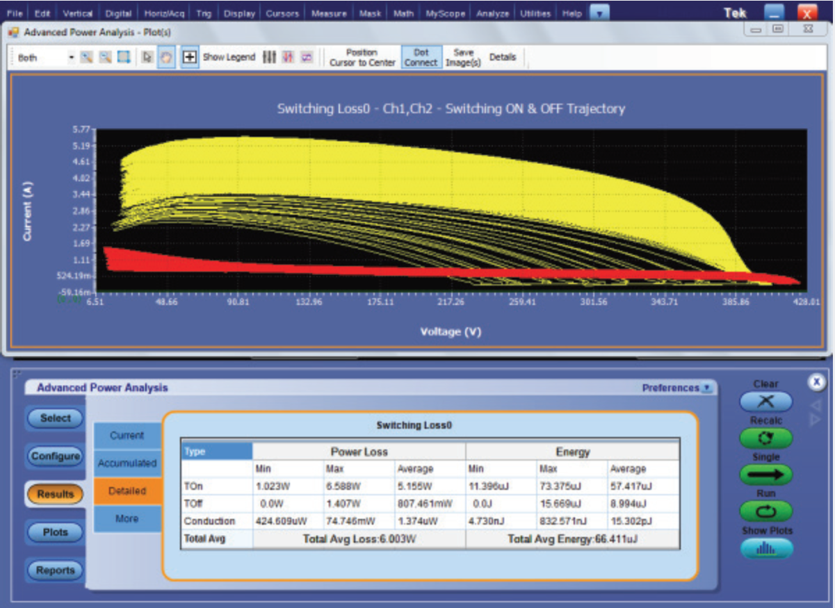
Although almost all components of a power supply contribute to energy losses, the majority of energy losses occur when the switching transistor transitions from an off to an on state and vice versa. A useful way to more fully understand switching loss is with a trajectory plot (available in DPOPWR software) of turn-on loss and turn-off loss for all switching cycles as shown below.

Switch on-off trajectory plot.
From there, you’ll want to check all the VGS signals for noise and bumps. This is an important step, since any unintended glitches on this terminal can lead to unwanted turn-on and shoot-through. To ensure that there’s no possibility of shoot-through, check the dead-time for sync rectifiers or H-bridges.
Next, verify timing relationships among gate drivers and related signals, making sure they match your design calculations.
To safely measure non-ground-reference signals, we suggest using differential probes with an appropriate voltage rating. Be sure not float the scope as the can have unpleasant consequences. You might want to consider TDP1000, TDP0500 or the P6251 High-Voltage Differential Probes depending on your application. Each of these probes achieves high-speed signal acquisition and measurement, and they have outstanding electrical performance, versatile device-under-test connectivity and are easy to use.
There’s no question that it can be hard to measure floating gate signals. We recommend probing at the input of the gate driver as this will allow you to verify dead-times between the top and bottom FETs.
Another pointer that will help you minimize crosstalk and improve accuracy is to measure currents at points of minimum voltage slew rate.
Be sure to check back soon for part 6 of our 10 part series for pointers on testing for switching and conduction losses.
See More Power Supply Measurement Tips in this 10-part series:
Part 1: Component Selection and Characterization for Power Supply Design
Part 2: Low-Voltage DC Circuit Power-On Test
Part 3: High-Voltage AC Circuit Power-On Test
Part 4: Digital and Analog Control Circuit Debug
Part 5: Testing Power Stage Switching Characteristics
Part 6: Switching and Conduction Loss Testing
Part 7: Power Supply Specification Check
Part 8: Power Line Compliance Testing
Part 9: EMI Troubleshooting and Pre-compliance
Part 10: Design Validation