Contact us
Live Chat with Tek representatives. Available 6:00 AM - 4:30 PM
Call us at
Available 6:00 AM – 5:00 PM (PST) Business Days
Download
Download Manuals, Datasheets, Software and more:
Feedback
RM5 Rackmount Kit Instructions
This document supports installing Tektronix 5/6 Series instruments in a rackmount kit to fit in a standard 19-inch equipment rack.
This manual applies to:
MSO56, MSO58, MSO64, MSO64B, MSO66B, MSO68B, MSO54B, MSO56B, MSO58B, RM5
Related Product Information
Bằng cách tải xuống, bạn đồng ý với các điều khoản và điều kiện của Thỏa thuận Tải xuống Hướng dẫn sử dụng.
Thỏa thuận Tải xuống Tài liệu Hướng dẫn
CHÚ Ý: vui lòng đọc kỹ các điều khoản và điều kiện sau trước khi tải xuống bất kỳ tài liệu nào từ trang web này. Bằng cách tải xuống hướng dẫn sử dụng từ trang web của Tektronix, bạn đồng ý với các điều khoản và điều kiện sau:
Hướng dẫn sử dụng cho các sản phẩm hiện đang được hỗ trợ:
Tektronix theo đây cấp phép và quyền cho chủ sở hữu các thiết bị Tektronix được tải xuống và sao chép các tài liệu hướng dẫn trên trang web này cho mục đích sử dụng nội bộ hoặc cá nhân của riêng họ. Tài liệu hướng dẫn cho các sản phẩm hiện đang được hỗ trợ không được sao chép để phân phối cho người khác trừ khi được Tektronix, Inc. cấp phép bằng văn bản cụ thể.
Hướng dẫn sử dụng của Tektronix có thể đã được sửa đổi để phản ánh các thay đổi được thực hiện đối với sản phẩm trong vòng đời sản xuất của sản phẩm đó. Do đó, các phiên bản hướng dẫn sử dụng khác nhau có thể tồn tại đối với bất kỳ sản phẩm cụ thể nào. Cần cẩn thận để đảm bảo rằng người dùng có được phiên bản hướng dẫn sử dụng phù hợp cho số sê-ri sản phẩm cụ thể.
Tài liệu hướng dẫn cho các sản phẩm không còn được hỗ trợ:
Tektronix không thể cung cấp tài liệu hướng dẫn cho các sản phẩm đo lường không còn đủ điều kiện hỗ trợ lâu dài. Tektronix theo đây cấp phép và quyền cho người khác sao chép và phân phối các bản sao của bất kỳ tài liệu hướng dẫn sản phẩm đo lường nào của Tektronix, bao gồm tài liệu hướng dẫn sử dụng, tài liệu hướng dẫn vận hành, tài liệu hướng dẫn dịch vụ và tương tự, mà (a) có Số bộ phận của Tektronix và (b) dành cho sản phẩm đo lường không còn được Tektronix hỗ trợ.
Tài liệu hướng dẫn của Tektronix có thể được sửa đổi để phản ánh các thay đổi được thực hiện đối với sản phẩm trong vòng đời sản xuất. Do đó, các phiên bản tài liệu hướng dẫn khác nhau có thể tồn tại cho bất kỳ sản phẩm cụ thể nào. Cần thận trọng để đảm bảo rằng người dùng có được phiên bản tài liệu hướng dẫn phù hợp cho số sê-ri sản phẩm cụ thể.
Giấy phép và quyền này không áp dụng cho bất kỳ tài liệu hướng dẫn hoặc ấn phẩm nào khác vẫn có sẵn từ Tektronix, hoặc cho bất kỳ tài liệu hướng dẫn hoặc ấn phẩm nào khác dành cho sản phẩm sản xuất video hoặc sản phẩm máy in màu.
Tuyên bố miễn trừ trách nhiệm:
Tektronix không đảm bảo tính chính xác hoặc đầy đủ của thông tin, văn bản, đồ họa, sơ đồ mạch, danh sách bộ phận hoặc tài liệu khác có trong bất kỳ hướng dẫn sử dụng sản phẩm đo lường nào hoặc ấn phẩm khác không do Tektronix cung cấp hoặc được sản xuất hoặc phân phối theo sự cho phép và giấy phép nêu trên.
Tektronix có thể thay đổi nội dung của trang web này hoặc các sản phẩm của mình bất cứ lúc nào mà không cần thông báo.
Giới hạn Trách nhiệm pháp lý:
TEKTRONIX SẼ KHÔNG CHỊU TRÁCH NHÁCH VỀ BẤT KỲ TỆN HẠI NÀO (BAO GỒM, KHÔNG GIỚI HẠN, BẤT KỲ TỆN HẠI DO HẬU QUẢ HOẶC NGẪU NHIÊN, TỆN HẠI DO MẤT LỢI NHUẬN, GIÁN ĐOẠN KINH DOANH, HOẶC DO VI PHẠM QUYỀN SỞ HỮU TRÍ TUỆ) PHÁT SINH TỪ VIỆC SỬ DỤNG BẤT KỲ TÀI LIỆU HƯỚNG DẪN SẢN PHẨM ĐO LƯỜNG HOẶC ANH PHẨM NÀO KHÁC DO TEKTRONIX SẢN XUẤT HOẶC PHÂN PHỐI THEO GIẤY PHÉP VÀ QUYỀN NÊU TRÊN.
Read Online
Important safety information
This manual contains information and warnings that must be followed by the user for safe operation and to keep the product in a safe condition.
To safely perform service on this product, see the Service safety summary that follows the General safety summary.
Service safety summary
The Service safety summary section contains additional information required to safely perform service on the product. Only qualified personnel should perform service procedures. Read this Service safety summary and the General safety summary before performing any service procedures.
To avoid electric shock
Do not touch exposed connections.
Do not service alone
Do not perform internal service or adjustments of this product unless another person capable of rendering first aid and resuscitation is present.
Disconnect power
To avoid electric shock, switch off the product power and disconnect the power cord from the mains power before removing any covers or panels, or opening the case for servicing.
Use care when servicing with power on
Dangerous voltages or currents may exist in this product. Disconnect power, remove battery (if applicable), and disconnect test leads before removing protective panels, soldering, or replacing components.
Verify safety after repair
Always recheck ground continuity and mains dielectric strength after performing a repair.
Kit description
The rackmount kit is a collection of parts that, once installed, configure the instrument for mounting into a standard 19-inch equipment rack. This rackmount kit supports all 5 Series MSO (except 5 Series MSO Low Profile) and 6 Series MSO instruments.
Minimum tool and equipment list
| Required tools and equipment | Part number |
|---|---|
| Screwdriver, Phillips, #2 | Standard tool |
| Screwdriver, T-10 Torx | Standard tool |
| Screwdriver, T-15 Torx | Standard tool |
| Screwdriver, T-8 Torx | Standard tool |
Kit parts list
The following table lists the parts for the kit; not all of the parts will be needed for your instrument setup.
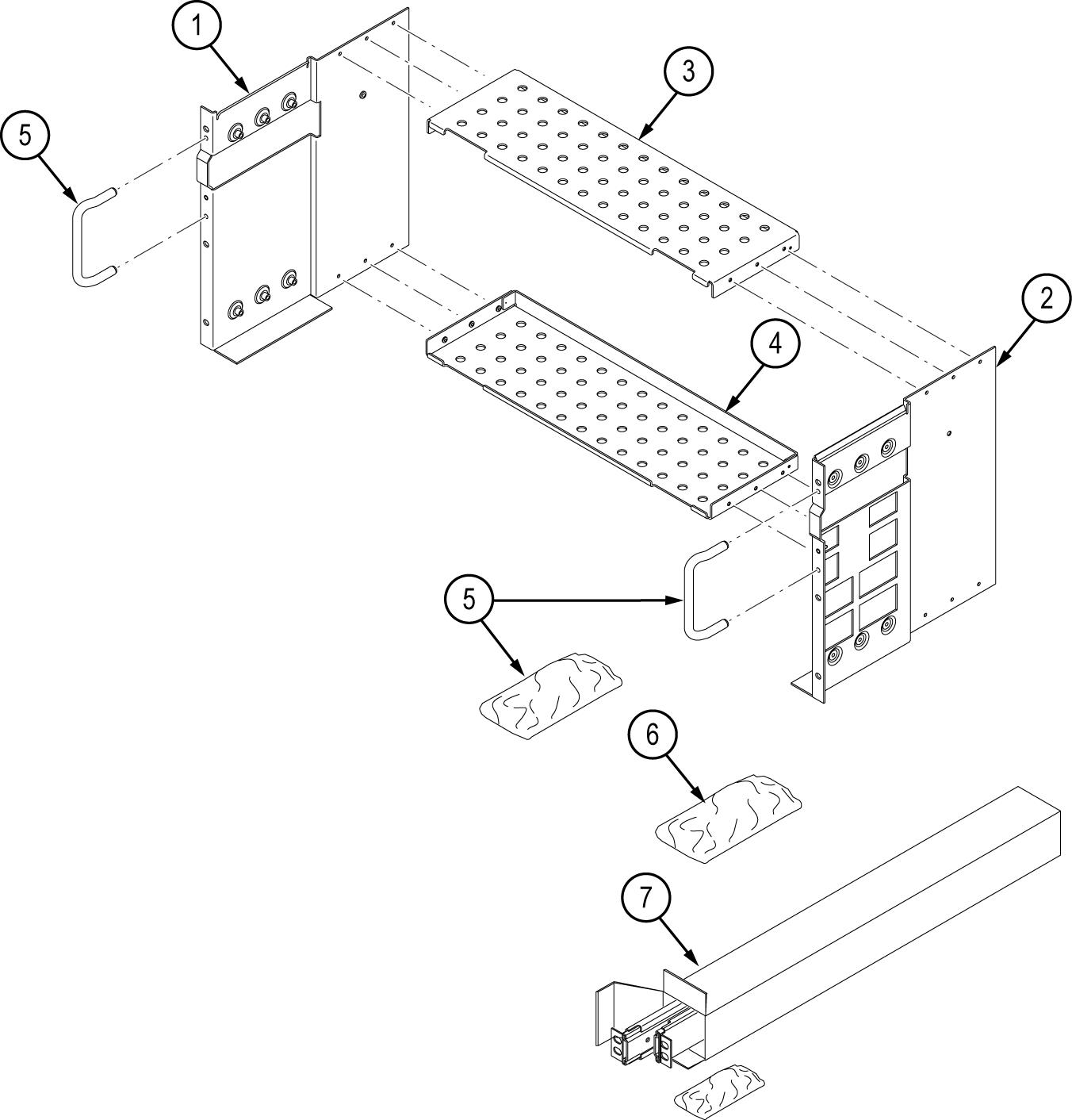
| Item | Quantity | Part number | Description |
|---|---|---|---|
| ----- | 1 each | 071-3523-XX | RM5 RACK MOUNT KIT INSTRUCTIONS |
| ----- | 1 each | 644-1088-XX | RACKMOUNT KIT CONSISTING OF THE FOLLOWING ITEMS: |
| 1 | 1 | 407-5871-XX | BRACKET, ASSEMBLY, LEFT, SAFETY CONTROLLED |
| 2 | 1 | 407-5872-XX | BRACKET, ASSEMBLY, RIGHT RACK KIT, SAFETY CONTROLLED |
| 3, 4 | 2 | 407-5870-XX | BRACKET, BOTTOM RACKMOUNT KIT, SAFETY CONTROLLED |
| 5 | 1 | 016-2114-XX | This kit includes the hardware required to assemble the rackmount kit and attach it to the instrument. |
| 016-2114-XX KIT, HARDWARE RACKMOUNT KIT CONSISTING OF THE FOLLOWING ITEMS: | |||
| 12 | 211-1584-XX | SCREW, MACHINE, M3X0.5X6MM PAN HEAD, TORX T10 | |
| 18 | 211-1653-XX | SCREW, M4 X 0.7 X 12 PAN HEAD, TORX T15 | |
| 2 | 367-0525-XX | HANDLE, CARRYING | |
| 4 | 212-0278-XX | SCREW, MACHINE; 10-32 X 0.5, FLH, 100 DEG,STL CD PL, POZ | |
| 6 | 1 | 016-2116-XX |
This kit includes the hardware required to mount the assembled instrument and rack kit to the instrument rack. |
| 016-2116-XX KIT, HARDWARE RACKMOUNT KIT CONSISTING OF THE FOLLOWING ITEMS: | |||
| 14 | 210-0833-XX | WASHER, RECESSED; 0.42 ID X 0.112 THK, STL NI PLATED, 0.588 OD | |
| 14 | 210-1061-XX | WASHER, FLAT; 0.203 ID X 0.625 OD X 0.062, ZINC PLATED STEEL | |
| 14 | 210-1548-XX | WASHER, FLAT 12 OD X 6.4 ID X 1.6THK | |
| 14 | 211-1218-XX | SCREW, M6 X 16MM OVAL HEAD, PHILLIPS | |
| 14 | 211-1219-XX | SCREW, M5 X 16MM OVAL HEAD, PHILLIPS | |
| 14 | 212-0591-XX | SCREW, MACHINE; 10-32X.750 OVAL HEAD, POZI | |
| 14 | 213-0199-XX | SCREW, MACHINE; 12-24 X 0.75, OVH, STL NP, POZ | |
| 7 | 1 | 351-1095-XX | SLIDE ASSY; PAIR, W/STD HARDWARE KIT AND REAR BRACKET, SAFETY CONTROLLED |
Warranted characteristics
When the instrument is installed according to the instructions in this document, the rackmounted instrument meets all warranted requirements listed in the instrument specification. Instruments mounted using methods other than those described in these instructions might not meet their warranted requirements.
For tables of the warranted characteristics, see Specifications in the specification and performance verification manual that applies to your instrument model.
 | CAUTION:The instrument might be damaged due to overheating. When installing multiple instruments in an instrument rack, the ambient temperature may go up. You assume the responsibility to provide adequate cooling to meet the ambient temperature requirements listed in the specifications.
|
The ambient temperature inside the instrument rack will vary depending on the location of the instrument within the instrument rack. Tektronix recommends that you measure the ambient temperature in the desired rack location before you install the instrument to ensure the operating temperature does not exceed the rated ambient temperature limit. If necessary, refer to the Environmental Specifications in your product documentation for the operating temperature limits.
Clearance requirements
The rack in which the individual instrument is mounted must provide the following clearance requirements:
- At least 218 mm (8.6 in) of vertical space
- A minimum width of 488 mm (19.2 in) between the left- and right-front rails in the rack. If possible, consider allowing at least 50.8 mm (2.0 in) on the right side and rear of the instrument for adequate airflow.
- A minimum inside depth of at least 384 mm (15.1 in) depth (from rack mounting ear to back of instrument). Airflow enters from the back of the instrument and exits on the right of the instrument when viewed from the front.
| CAUTION:Adhering to these requirements mounts the rack-adapted instrument with enough clearance for air circulation and accommodation of the power cord and mounting hardware. Failure to provide these clearances can result in overheating and can cause the instrument to operate improperly or fail.
|
Installation instructions
These instructions are for qualified service personnel who are familiar with servicing the product. If you need further details for disassembling or reassembling the product, refer to the appropriate product manual. Contact your nearest Tektronix, Inc., Service Center or Tektronix Factory Service for installation assistance.
Assemble the instrument on the rack platform
A 5 Series MSO is shown in the illustrations.
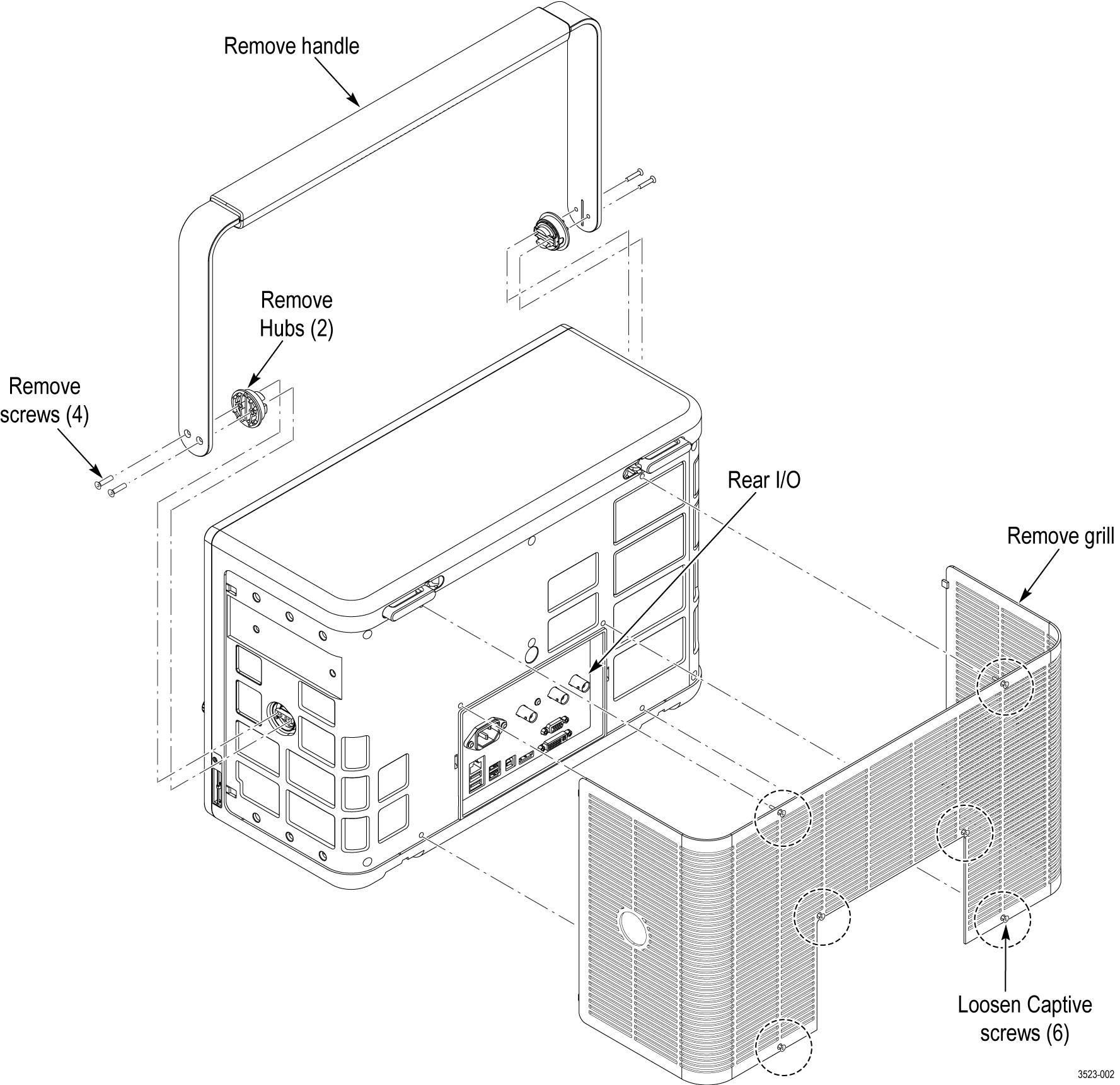
- Remove the handle, hubs, and grill as shown. Save the handle, hubs, hub screws, and grill for future use.
Figure 1. Prepare the instrument 
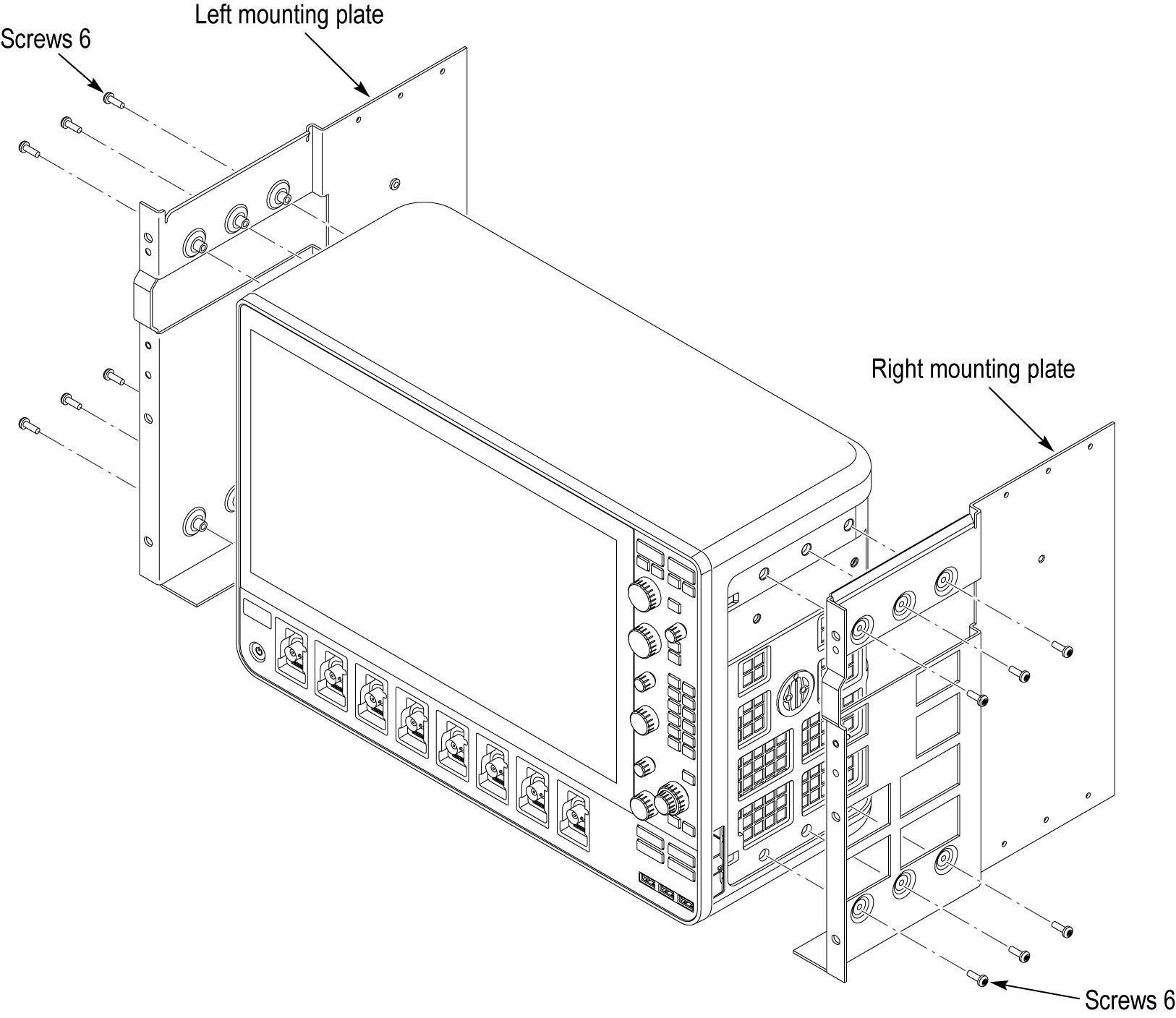
- Install the left and right mounting plates. Use the M4 screws from item 5.
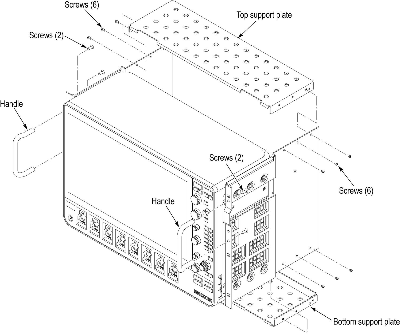
Figure 2. Mounting plate installation - Install the top and bottom support plates and handle as shown. Use the M3 screws from item 5 to assemble the support plates. Use the 10-32 flat-head screws from item 5 to attach the handles.
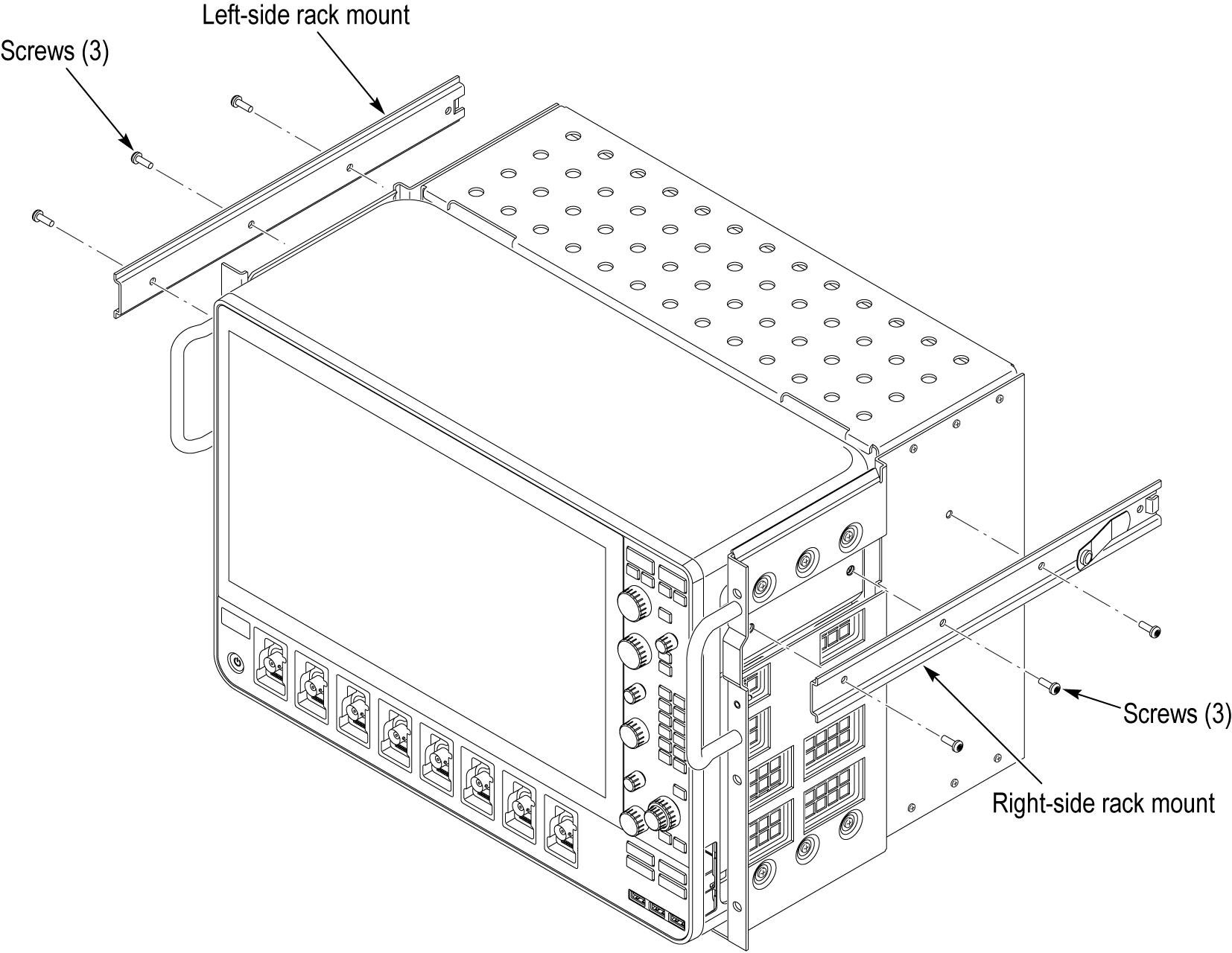
Figure 3. Support plate installation - Install the left-side and right-side rack mounts as shown. Use M4 screws from item 5 to attach the slides.
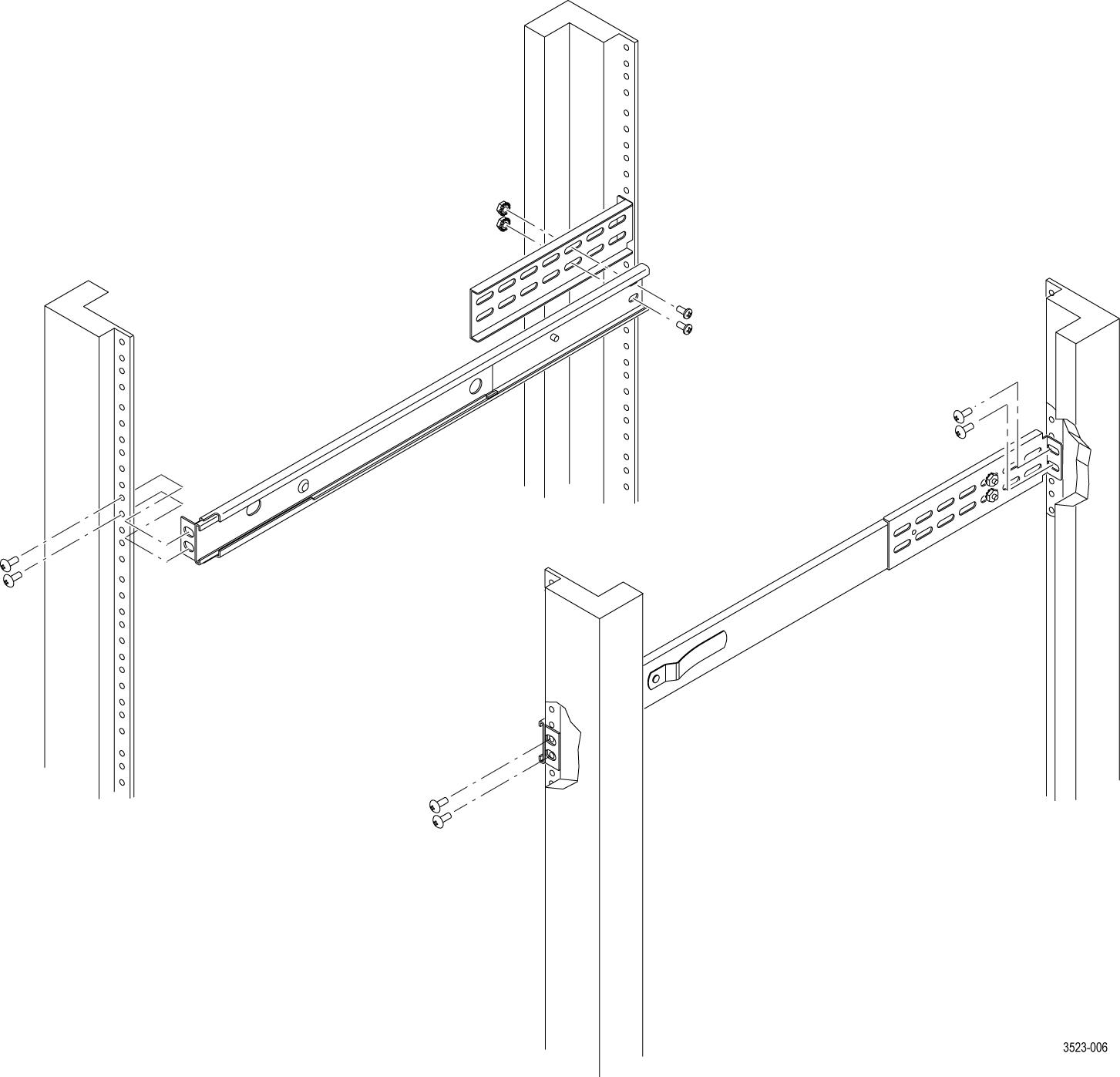
Figure 4. Rack mount installation - Locate the rack slides and using hardware from items 6 and 7, as appropriate for your rack, install the rack slides in your equipment rack.
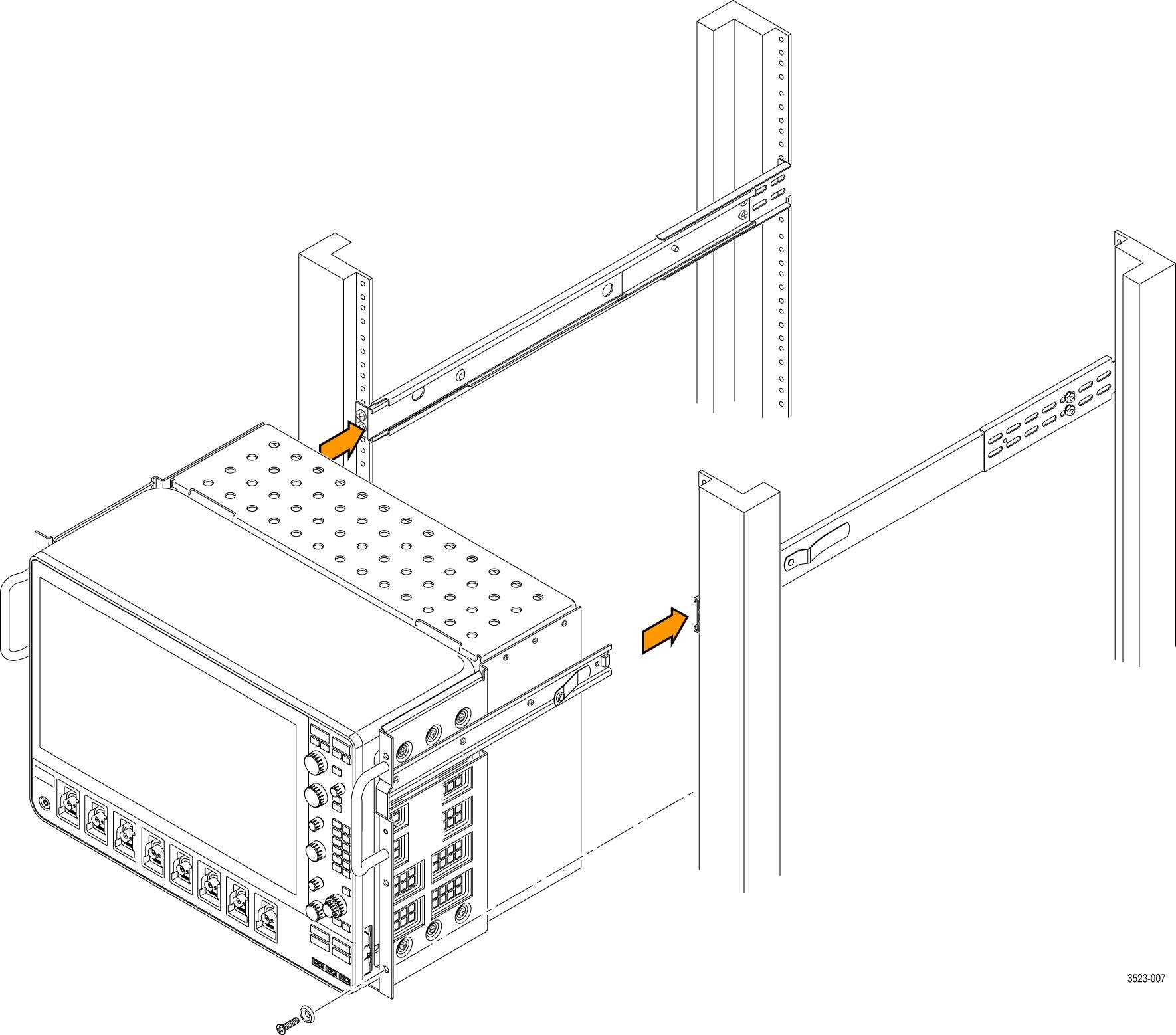
Figure 5. Installing the rail slides - Install the rack platform in your equipment rack by inserting the platform into the slides as shown.
Figure 6. Installation of rack mounted instrument assembly in rack (top view) WARNING:To avoid personal injury and prevent the instrument from tipping or dropping, use two or more people to install this instrument into the rack cabinet. After completing the installation procedure, verify that the instrument and the rack cabinet will not tip forward while the instrument is in the extended position. Do not leave the instrument extended when finished accessing the instrument. - Install the power cord. Provide access to a power plug or mains disconnect switch for turning the instrument on/off.
- Optionally install any cables you need connected to the instrument rear panel.
- Slide the instrument into the equipment rack, and secure the instrument to the rack using standard rack hardware.
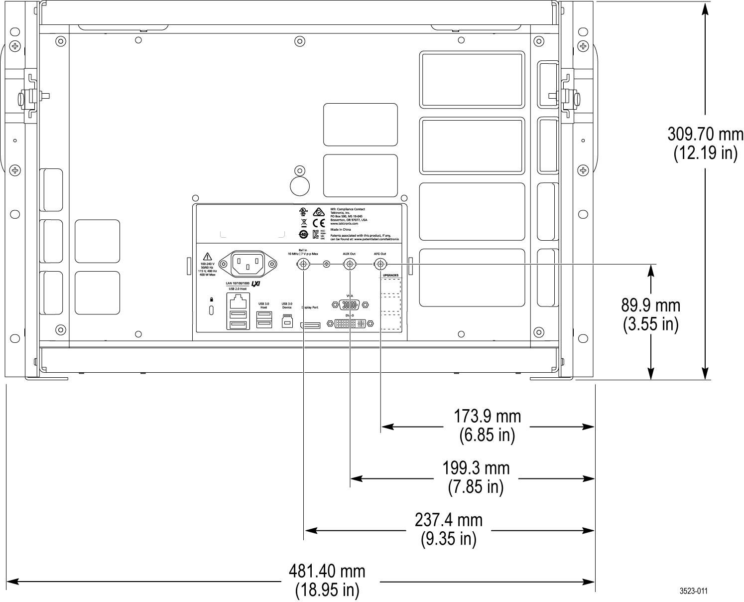
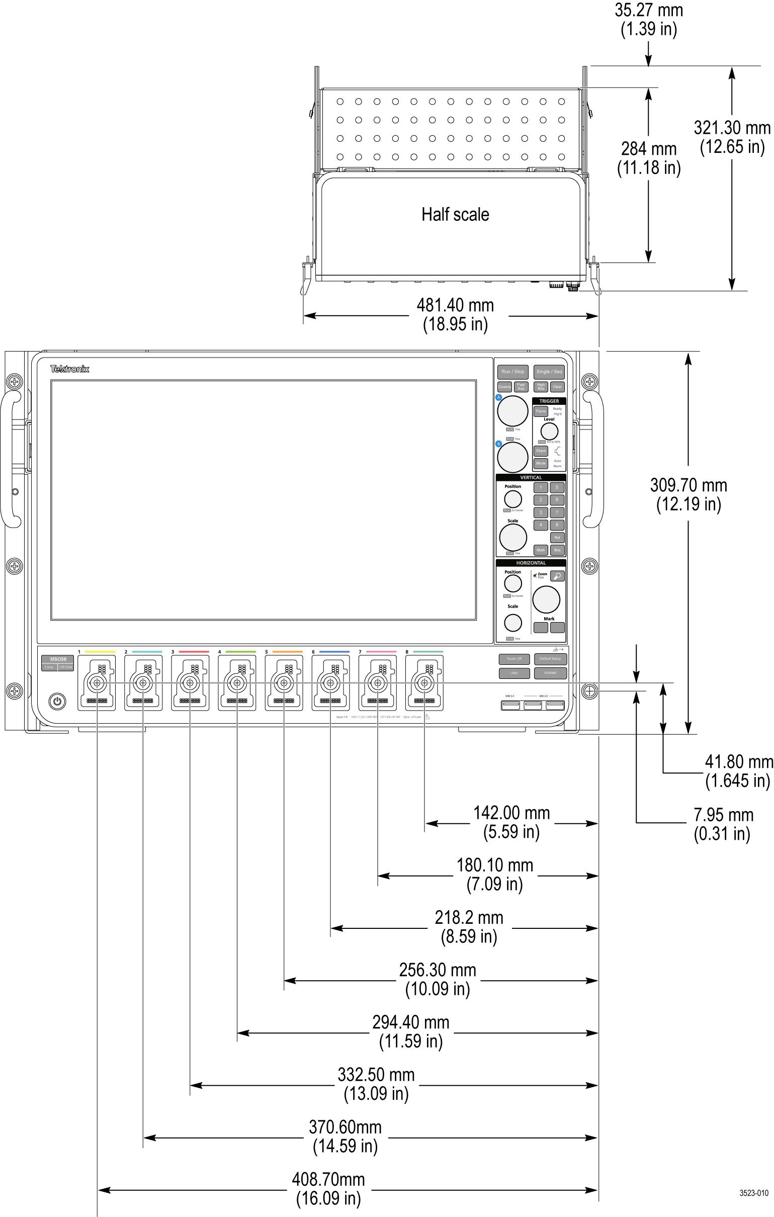
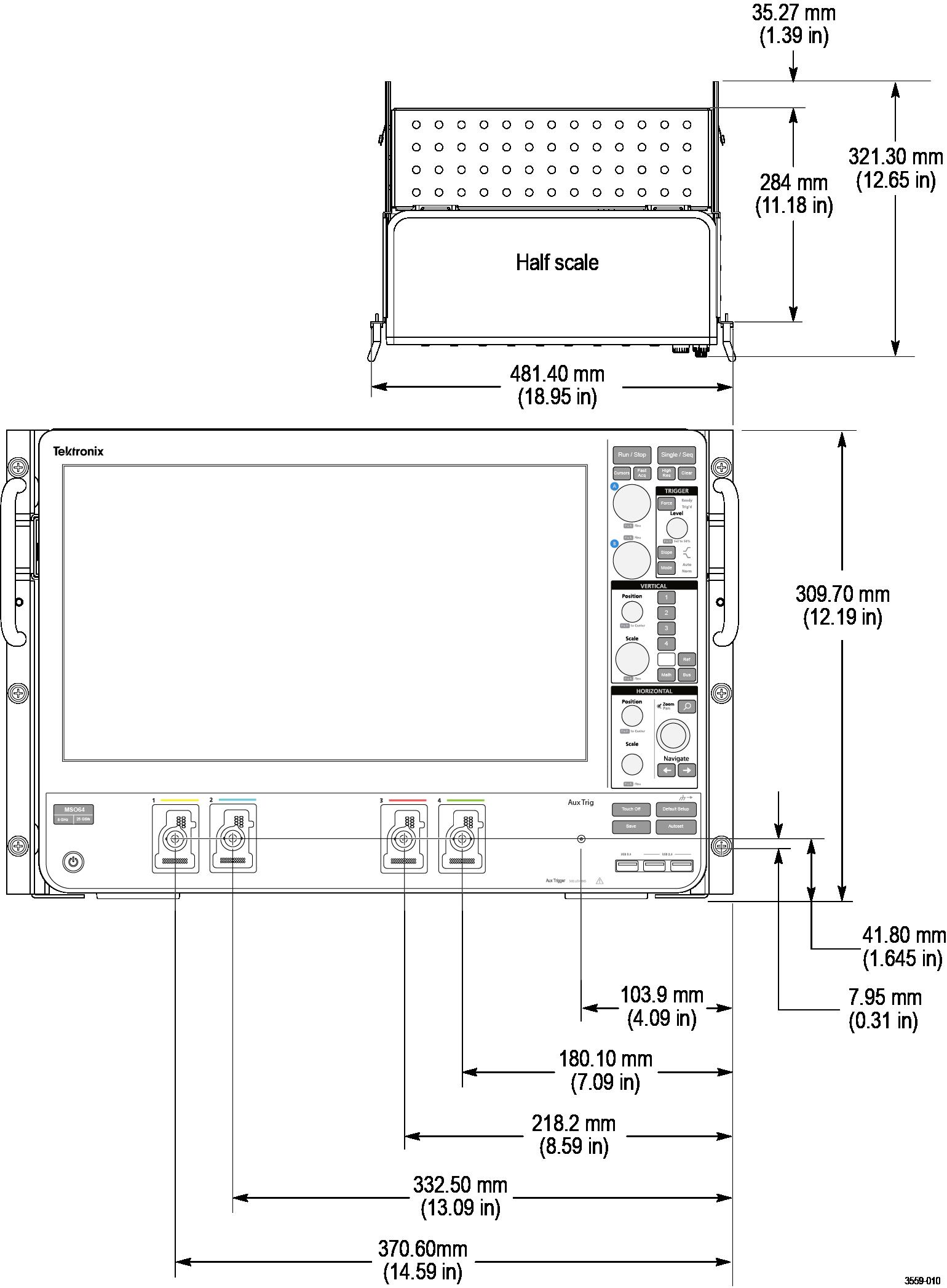
Dimensions
Front panel
Rear panel