연락처
텍트로닉스 담당자와 실시간 상담 6:00am-4:30pm PST에 이용 가능
전화 문의
9:00am-6:00PM KST에 이용 가능
다운로드
매뉴얼, 데이터 시트, 소프트웨어 등을 다운로드할 수 있습니다.
피드백
RM5 Rackmount Kit Instructions
This document supports installing Tektronix 5/6 Series instruments in a rackmount kit to fit in a standard 19-inch equipment rack.
이 매뉴얼은 다음에 적용됩니다.:
MSO56, MSO58, MSO64, MSO64B, MSO66B, MSO68B, MSO54B, MSO56B, MSO58B, RM5
관련 제품 정보
다운로드하면 매뉴얼 다운로드 계약 약관에 동의하게 됩니다.
설명서 다운로드 계약
참고: 이 웹 사이트에서 문서를 다운로드하기 전에 아래 약관을 주의 깊게 읽어보십시오. 텍트로닉스 웹 사이트에서 설명서를 다운로드하면 아래 약관에 동의한 것으로 간주됩니다.
현재 지원되는 제품의 설명서:
Tektronix 장비 소유자에게는 내부 또는 개인용으로 이 웹 사이트에서 설명서를 다운로드하고 복제할 수 있는 권한 및 사용권이 부여됩니다. 현재 지원되는 제품의 설명서는 Tektronix, Inc.에서 별도로 서면으로 승인하지 않는 한 다른 사람에게 배포하기 위해 복제될 수 없습니다.
Tektronix 설명서는 제조 기간 동안 제품의 변경 내용을 반영하도록 개정될 수 있습니다. 따라서 특정 제품에 대해 서로 다른 설명서 버전이 존재할 수 있습니다. 특정 제품 시리얼 넘버에 대해 올바른 설명서 버전을 가져오도록 주의를 기울여야 합니다.
더 이상 지원되지 않는 제품의 설명서:
Tektronix는 장기간 지원에 더 이상 적합하지 않은 측정 제품용 설명서를 제공할 수 없습니다. Tektronix는 Tektronix에서 더 이상 지원하지 않는 (a) Tektronix 부품 번호 (b) 측정 제품용 사용 설명서, 작업자 설명서, 서비스 설명서 등을 비롯한 Tektronix 측정 제품 설명서 복사본을 복제하고 배포할 수 있는 권한 및 사용권을 제공합니다.
Tektronix 설명서는 제조 기간 동안 제품의 변경 내용을 반영하도록 개정될 수 있습니다. 따라서 특정 제품에 대해 서로 다른 설명서 버전이 존재할 수 있습니다. 특정 제품 시리얼 넘버에 대해 올바른 설명서 버전을 가져오도록 주의를 기울여야 합니다.
이 권한 및 사용권은 Tektronix에서 계속해서 제공되는 모든 설명서나 기타 출판물 또는 비디오 프러덕션 제품이나 컬러 프린터 제품용 설명서나 기타 출판물에는 적용되지 않습니다.
부인:
Tektronix는 Tektronix에서 제공하지 않거나 위에서 언급된 권한 및 사용권에 따라 작성 또는 배포된 모든 측정 제품 설명서나 기타 출판물에 포함된 정보, 텍스트, 그래픽, 도식, 부품 목록 또는 기타 자료의 정확성 또는 완전성을 보장하지 않습니다.
Tektronix는 언제든지 예고 없이 이 웹 사이트나 제품의 콘텐츠를 변경할 수 있습니다.
책임의 제한:
TEKTRONIX는 위에서 언급된 권한 및 사용권에 따라 작성 또는 배포된 기타 출판물이나 모든 측정 제품 설명서 사용으로 인한 손해(결과적, 우박적 손해, 이익 손실, 업무 중단, 지적 재산권 침해)에 대해 책임을 지지 않습니다.
Read Online
Important safety information
This manual contains information and warnings that must be followed by the user for safe operation and to keep the product in a safe condition.
To safely perform service on this product, see the Service safety summary that follows the General safety summary.
Service safety summary
The Service safety summary section contains additional information required to safely perform service on the product. Only qualified personnel should perform service procedures. Read this Service safety summary and the General safety summary before performing any service procedures.
To avoid electric shock
Do not touch exposed connections.
Do not service alone
Do not perform internal service or adjustments of this product unless another person capable of rendering first aid and resuscitation is present.
Disconnect power
To avoid electric shock, switch off the product power and disconnect the power cord from the mains power before removing any covers or panels, or opening the case for servicing.
Use care when servicing with power on
Dangerous voltages or currents may exist in this product. Disconnect power, remove battery (if applicable), and disconnect test leads before removing protective panels, soldering, or replacing components.
Verify safety after repair
Always recheck ground continuity and mains dielectric strength after performing a repair.
Kit description
The rackmount kit is a collection of parts that, once installed, configure the instrument for mounting into a standard 19-inch equipment rack. This rackmount kit supports all 5 Series MSO (except 5 Series MSO Low Profile) and 6 Series MSO instruments.
Minimum tool and equipment list
| Required tools and equipment | Part number |
|---|---|
| Screwdriver, Phillips, #2 | Standard tool |
| Screwdriver, T-10 Torx | Standard tool |
| Screwdriver, T-15 Torx | Standard tool |
| Screwdriver, T-8 Torx | Standard tool |
Kit parts list
The following table lists the parts for the kit; not all of the parts will be needed for your instrument setup.
| Item | Quantity | Part number | Description |
|---|---|---|---|
| ----- | 1 each | 071-3523-XX | RM5 RACK MOUNT KIT INSTRUCTIONS |
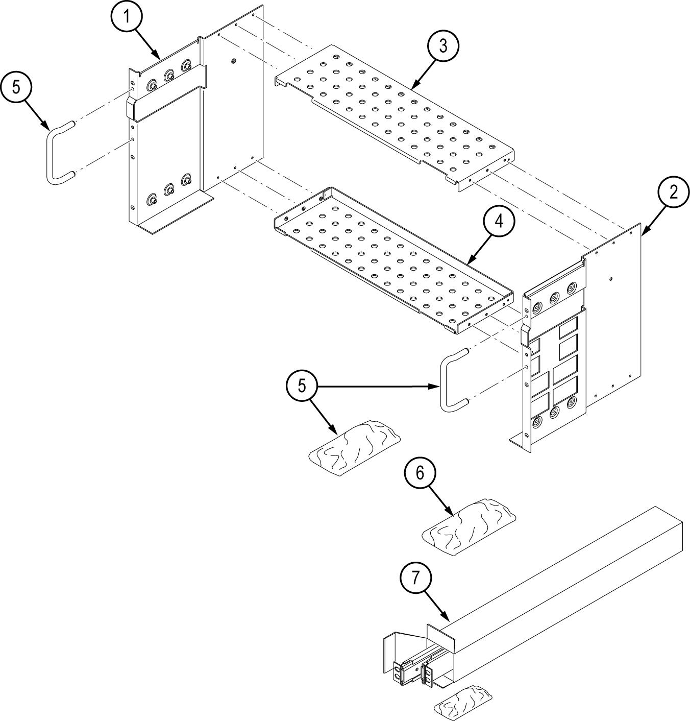
| ----- | 1 each | 644-1088-XX | RACKMOUNT KIT CONSISTING OF THE FOLLOWING ITEMS: |
| 1 | 1 | 407-5871-XX | BRACKET, ASSEMBLY, LEFT, SAFETY CONTROLLED |
| 2 | 1 | 407-5872-XX | BRACKET, ASSEMBLY, RIGHT RACK KIT, SAFETY CONTROLLED |
| 3, 4 | 2 | 407-5870-XX | BRACKET, BOTTOM RACKMOUNT KIT, SAFETY CONTROLLED |
| 5 | 1 | 016-2114-XX | This kit includes the hardware required to assemble the rackmount kit and attach it to the instrument. |
| 016-2114-XX KIT, HARDWARE RACKMOUNT KIT CONSISTING OF THE FOLLOWING ITEMS: | |||
| 12 | 211-1584-XX | SCREW, MACHINE, M3X0.5X6MM PAN HEAD, TORX T10 | |
| 18 | 211-1653-XX | SCREW, M4 X 0.7 X 12 PAN HEAD, TORX T15 | |
| 2 | 367-0525-XX | HANDLE, CARRYING | |
| 4 | 212-0278-XX | SCREW, MACHINE; 10-32 X 0.5, FLH, 100 DEG,STL CD PL, POZ | |
| 6 | 1 | 016-2116-XX |
This kit includes the hardware required to mount the assembled instrument and rack kit to the instrument rack. |
| 016-2116-XX KIT, HARDWARE RACKMOUNT KIT CONSISTING OF THE FOLLOWING ITEMS: | |||
| 14 | 210-0833-XX | WASHER, RECESSED; 0.42 ID X 0.112 THK, STL NI PLATED, 0.588 OD | |
| 14 | 210-1061-XX | WASHER, FLAT; 0.203 ID X 0.625 OD X 0.062, ZINC PLATED STEEL | |
| 14 | 210-1548-XX | WASHER, FLAT 12 OD X 6.4 ID X 1.6THK | |
| 14 | 211-1218-XX | SCREW, M6 X 16MM OVAL HEAD, PHILLIPS | |
| 14 | 211-1219-XX | SCREW, M5 X 16MM OVAL HEAD, PHILLIPS | |
| 14 | 212-0591-XX | SCREW, MACHINE; 10-32X.750 OVAL HEAD, POZI | |
| 14 | 213-0199-XX | SCREW, MACHINE; 12-24 X 0.75, OVH, STL NP, POZ | |
| 7 | 1 | 351-1095-XX | SLIDE ASSY; PAIR, W/STD HARDWARE KIT AND REAR BRACKET, SAFETY CONTROLLED |
Warranted characteristics
When the instrument is installed according to the instructions in this document, the rackmounted instrument meets all warranted requirements listed in the instrument specification. Instruments mounted using methods other than those described in these instructions might not meet their warranted requirements.
For tables of the warranted characteristics, see Specifications in the specification and performance verification manual that applies to your instrument model.
 | CAUTION:The instrument might be damaged due to overheating. When installing multiple instruments in an instrument rack, the ambient temperature may go up. You assume the responsibility to provide adequate cooling to meet the ambient temperature requirements listed in the specifications.
|
The ambient temperature inside the instrument rack will vary depending on the location of the instrument within the instrument rack. Tektronix recommends that you measure the ambient temperature in the desired rack location before you install the instrument to ensure the operating temperature does not exceed the rated ambient temperature limit. If necessary, refer to the Environmental Specifications in your product documentation for the operating temperature limits.
Clearance requirements
The rack in which the individual instrument is mounted must provide the following clearance requirements:
- At least 218 mm (8.6 in) of vertical space
- A minimum width of 488 mm (19.2 in) between the left- and right-front rails in the rack. If possible, consider allowing at least 50.8 mm (2.0 in) on the right side and rear of the instrument for adequate airflow.
- A minimum inside depth of at least 384 mm (15.1 in) depth (from rack mounting ear to back of instrument). Airflow enters from the back of the instrument and exits on the right of the instrument when viewed from the front.
| CAUTION:Adhering to these requirements mounts the rack-adapted instrument with enough clearance for air circulation and accommodation of the power cord and mounting hardware. Failure to provide these clearances can result in overheating and can cause the instrument to operate improperly or fail.
|
Installation instructions
These instructions are for qualified service personnel who are familiar with servicing the product. If you need further details for disassembling or reassembling the product, refer to the appropriate product manual. Contact your nearest Tektronix, Inc., Service Center or Tektronix Factory Service for installation assistance.
Assemble the instrument on the rack platform
A 5 Series MSO is shown in the illustrations.
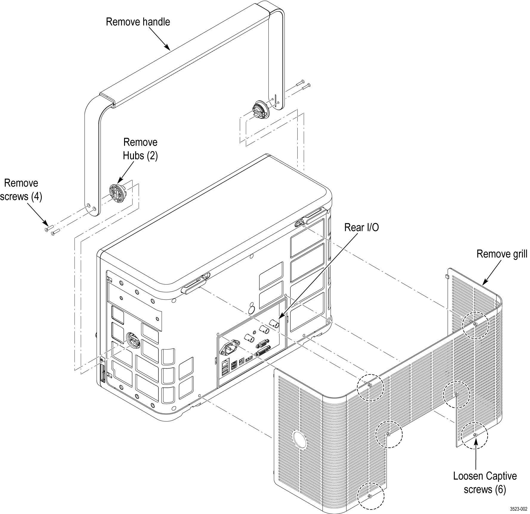
- Remove the handle, hubs, and grill as shown. Save the handle, hubs, hub screws, and grill for future use.
Figure 1. Prepare the instrument 
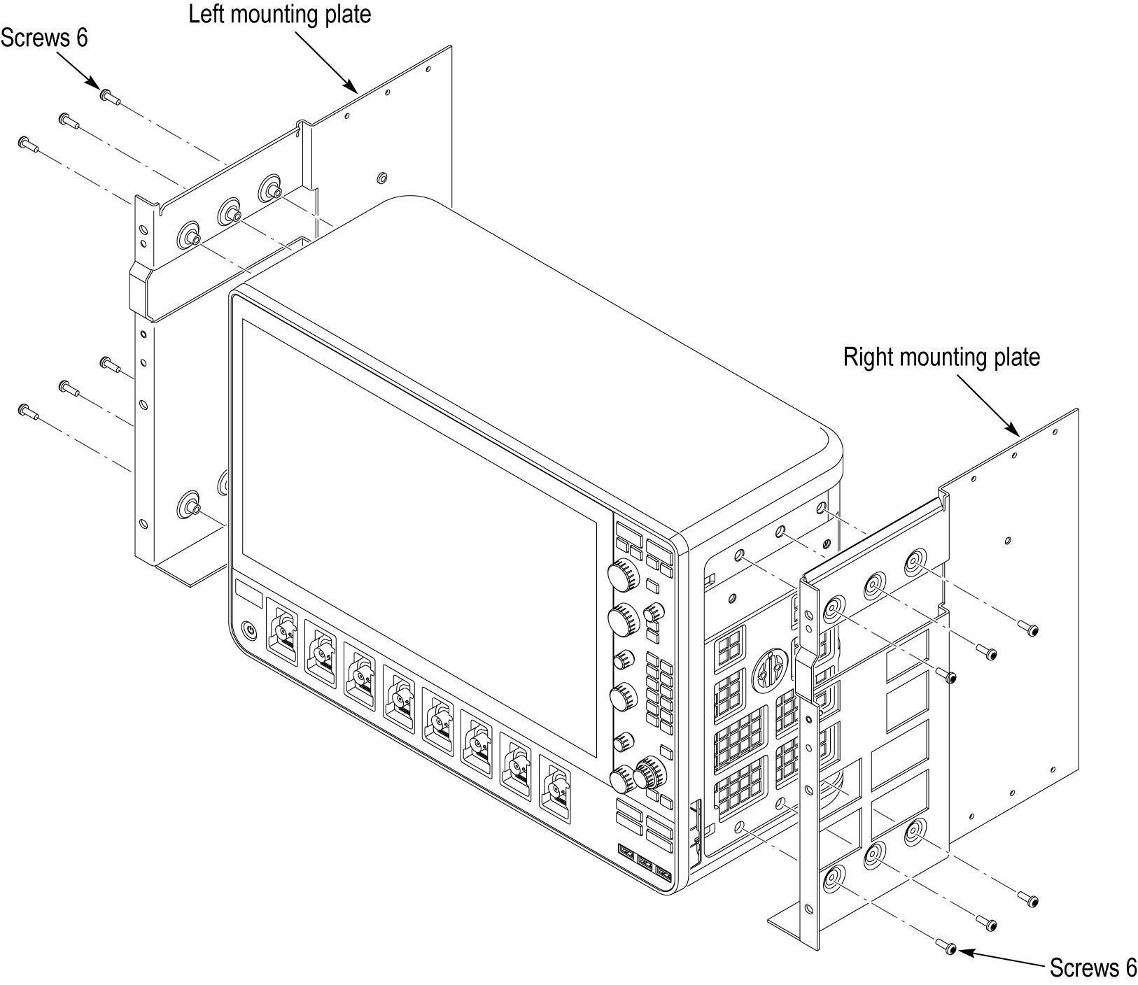
- Install the left and right mounting plates. Use the M4 screws from item 5.
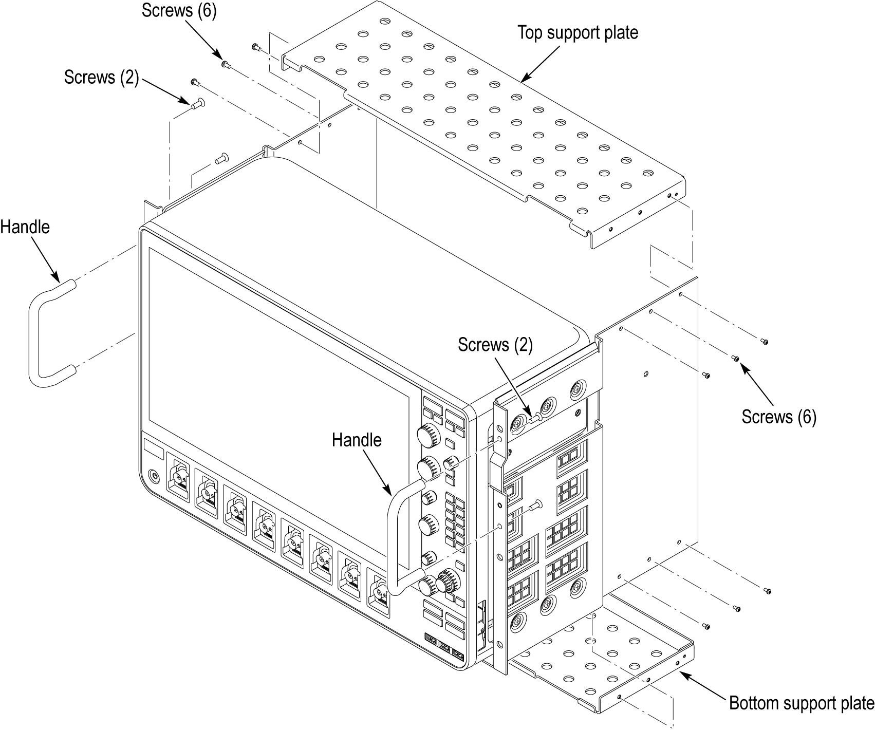
Figure 2. Mounting plate installation - Install the top and bottom support plates and handle as shown. Use the M3 screws from item 5 to assemble the support plates. Use the 10-32 flat-head screws from item 5 to attach the handles.
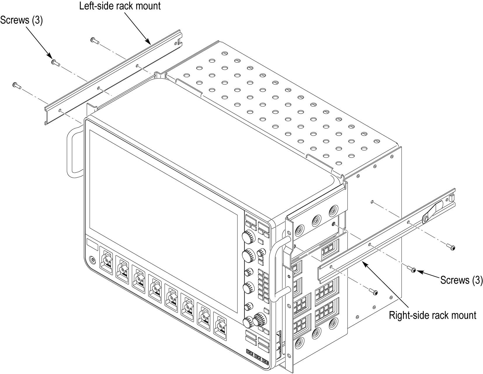
Figure 3. Support plate installation - Install the left-side and right-side rack mounts as shown. Use M4 screws from item 5 to attach the slides.
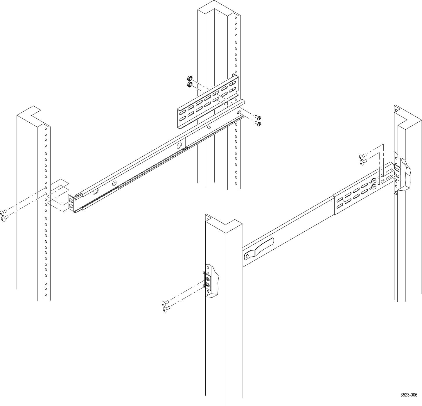
Figure 4. Rack mount installation - Locate the rack slides and using hardware from items 6 and 7, as appropriate for your rack, install the rack slides in your equipment rack.
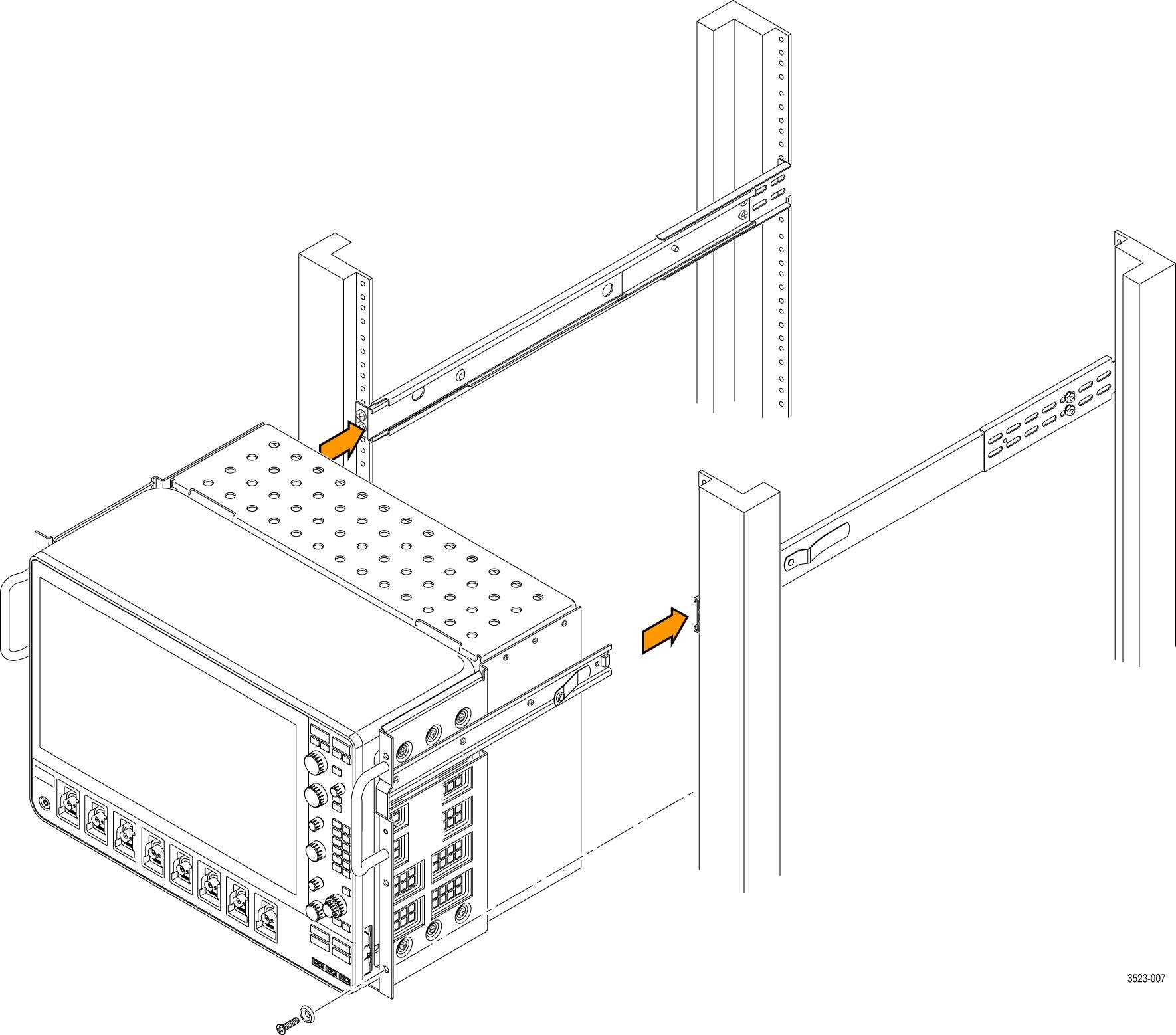
Figure 5. Installing the rail slides - Install the rack platform in your equipment rack by inserting the platform into the slides as shown.
Figure 6. Installation of rack mounted instrument assembly in rack (top view) WARNING:To avoid personal injury and prevent the instrument from tipping or dropping, use two or more people to install this instrument into the rack cabinet. After completing the installation procedure, verify that the instrument and the rack cabinet will not tip forward while the instrument is in the extended position. Do not leave the instrument extended when finished accessing the instrument. - Install the power cord. Provide access to a power plug or mains disconnect switch for turning the instrument on/off.
- Optionally install any cables you need connected to the instrument rear panel.
- Slide the instrument into the equipment rack, and secure the instrument to the rack using standard rack hardware.
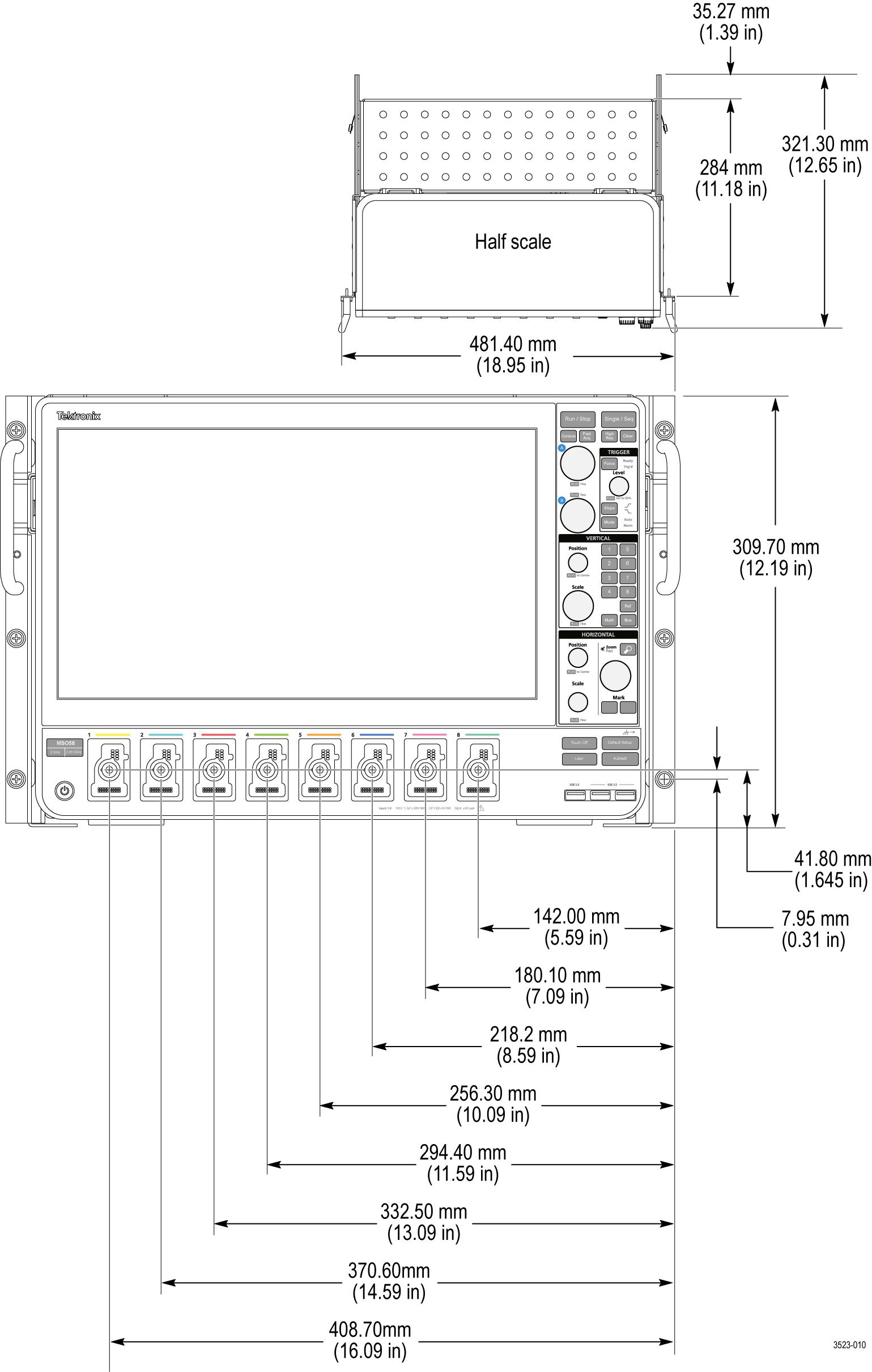
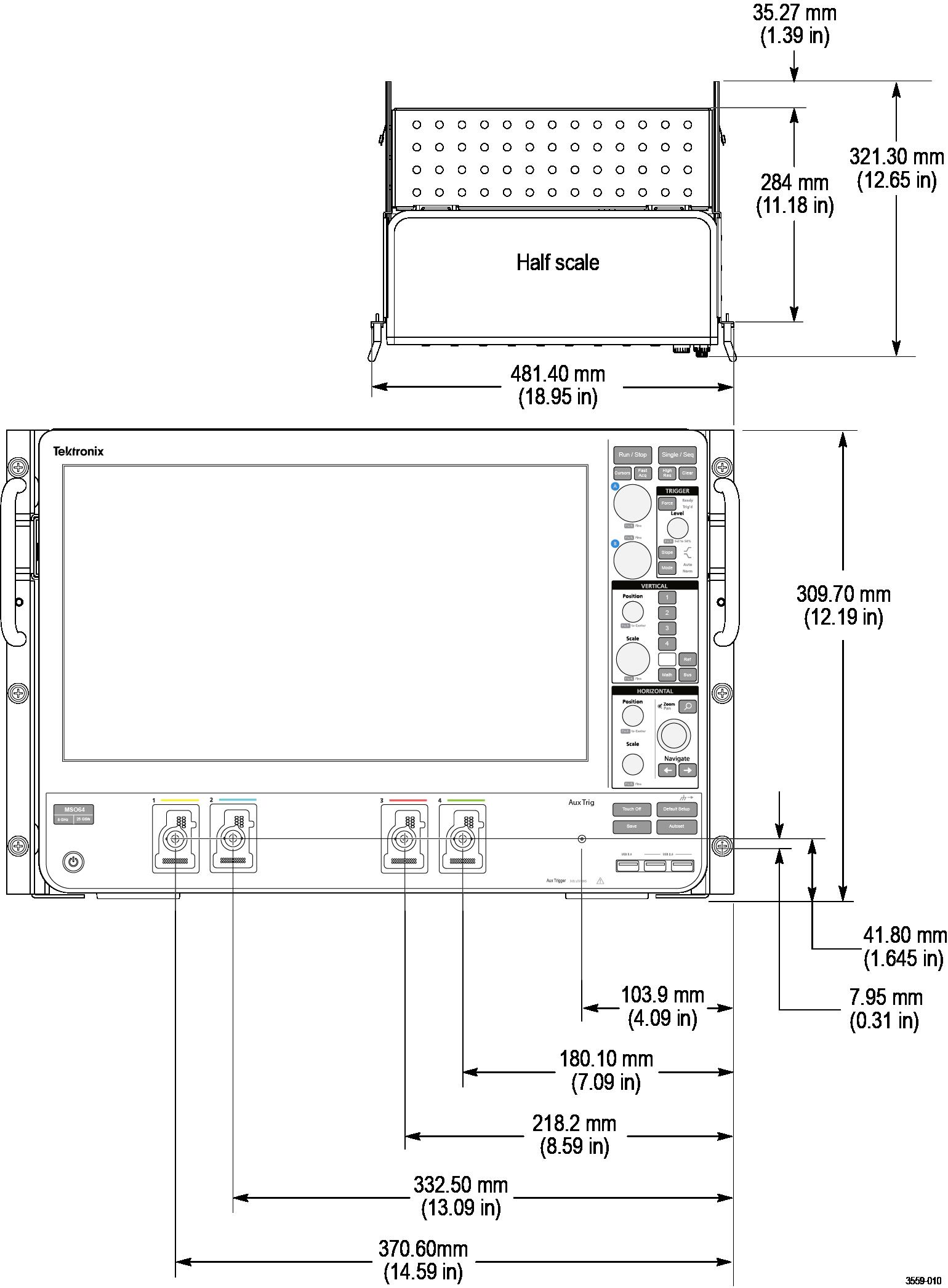
Dimensions
Front panel
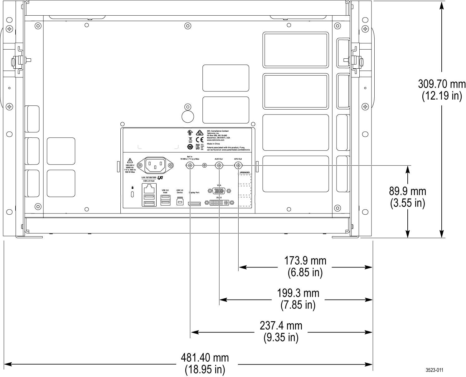
Rear panel