Question :
What does “Probe Dynamic Range” mean and how does the 5 and 6 Series MSO indicate it?
Answer :
Oscilloscope probes which contain active circuitry, especially with amplifiers in the signal path, have a limited dynamic range over which the probe behaves linearly. When input signals exceed this range, the signal may be distorted. (Such probes also have a “maximum non-destructive voltage” or absolute maximum input range beyond which the probe and/or the oscilloscope may be permanently damaged!) Both of these specifications are typically shown in the probe data sheet. See probes »
For example:
| Tektronix TekVPI Probe | Input Dynamic Range Spec (Attenuation Range) | Maximum Non-Destruct Voltage (Attenuation Range) |
|---|---|---|
| TAP1500 active probe | ±8 V | ±15 V |
| TAP2500/3500 active probe | ±4 V | ±30 V |
| TDP500/1000 differential probe | ±42 V | ±100 V |
| TDP1500 differential probe | ±8.5 V (10X), ±850 mV (1X) | ±25 V |
| TDP3500 differential probe | ±2 V | ±15 V |
| TMDP0200 differential probe | ±75 V (25X), ±750 V (250X) | 300 V CAT III |
| THDP0200 differential probe | ±150 V (50X), ±1500 V (500X) | 600 V CAT III |
| THDP0100 differential probe | ±600 V (100X), ±600 V (100X) | 1000 V CAT III |
| TIVM differential probes | ±0.5 V (1X) through ±25 V (50X) | ±4.3 V (1X) through ±200 V (50X) |
| TIVH differential probes | ±0.5 V (1X) through ±1250 V (2500X) | ±25 V (1X) through ±2500 V (2500X) |
When a signal is too large at the oscilloscope’s analog-to-digital converter (ADC), the signal is typically “clipped” and the peaks of the signal become flat horizontal lines, often at the top and bottom of the oscilloscope graticule. However, when the signal exceeds the probe’s dynamic range spec (but still within the maximum non-destruct voltage range), the distortion may be more subtle. If it goes uncorrected, the measurement accuracy suffers.
Many Tektronix TekVPI probes contain the dynamic range information and communicate this value to the oscilloscope when the probe is attached or the oscilloscope is powered on. This information can be used to indicate the probe’s dynamic range on the oscilloscope display, providing assurance that the signal is not over-driving the probe. This is especially critical when the oscilloscope is set to a vertical scale value larger than the dynamic range of the probe.
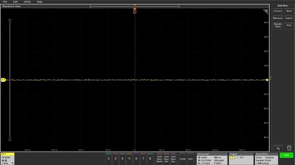
For example, when a TDP1000 differential probe is connected to the oscilloscope, the probe dynamic range indicator looks like this, showing that the probe’s dynamic range is ±42 V:
This FAQ Applies to:
Product Series: 5 Series MSO Low Profile 5 Series B MSO 6 Series B MSO
Product:
FAQ ID 474196
View all FAQs »