Contact us
Call us at
Available 6:00 AM – 5:00 PM (PST) Business Days
Download
Download Manuals, Datasheets, Software and more:
Feedback
6 Series B MSO Service Manual
This manual provides theory of operation, service instructions and a list of replaceable parts for the 6 Series B MSO instruments.
This manual applies to:
MSO64B, MSO66B, MSO68B
By downloading, you agree to the terms and conditions of the Manuals Download Agreement.
Manuals Download Agreement
ATTENTION: please read the following terms and conditions carefully before downloading any documents from this website. By downloading manuals from Tektronix' website, you agree to the following terms and conditions:
Manuals for Products That Are Currently Supported:
Tektronix hereby grants permission and license to owners of Tektronix instruments to download and reproduce the manuals on this website for their own internal or personal use. Manuals for currently supported products may not be reproduced for distribution to others unless specifically authorized in writing by Tektronix, Inc.
A Tektronix manual may have been revised to reflect changes made to the product during its manufacturing life. Thus, different versions of a manual may exist for any given product. Care should be taken to ensure that one obtains the proper manual version for a specific product serial number.
Manuals for Products That Are No Longer Supported:
Tektronix cannot provide manuals for measurement products that are no longer eligible for long term support. Tektronix hereby grants permission and license for others to reproduce and distribute copies of any Tektronix measurement product manual, including user manuals, operator's manuals, service manuals, and the like, that (a) have a Tektronix Part Number and (b) are for a measurement product that is no longer supported by Tektronix.
A Tektronix manual may be revised to reflect changes made to the product during its manufacturing life. Thus, different versions of a manual may exist for any given product. Care should be taken to ensure that one obtains the proper manual version for a specific product serial number.
This permission and license does not apply to any manual or other publication that is still available from Tektronix, or to any manual or other publication for a video production product or a color printer product.
Disclaimer:
Tektronix does not warrant the accuracy or completeness of the information, text, graphics, schematics, parts lists, or other material contained within any measurement product manual or other publication that is not supplied by Tektronix or that is produced or distributed in accordance with the permission and license set forth above.
Tektronix may make changes to the content of this website or to its products at any time without notice.
Limitation of Liability:
TEKTRONIX SHALL NOT BE LIABLE FOR ANY DAMAGES WHATSOEVER (INCLUDING, WITHOUT LIMITATION, ANY CONSEQUENTIAL OR INCIDENTAL DAMAGES, DAMAGES FOR LOSS OF PROFITS, BUSINESS INTERRUPTION, OR FOR INFRINGEMENT OF INTELLECTUAL PROPERTY) ARISING OUT OF THE USE OF ANY MEASUREMENT PRODUCT MANUAL OR OTHER PUBLICATION PRODUCED OR DISTRIBUTED IN ACCORDANCE WITH THE PERMISSION AND LICENSE SET FORTH ABOVE.
Read Online
MAINTENANCE
- Preventing ESD
- Inspection and cleaning
- Exterior cleaning (other than display)
- Flat panel display cleaning
- Interior cleaning
- Lubrication
- Returning the instrument for service
- Removal and replace procedures
- Required equipment
- Remove front-panel knobs
- Remove SATA riser board assembly
- Remove feet
- Remove handle
- Remove rear grill and case
- Remove rear chassis assembly
- Remove the baffle bracket
- Remove the power supply assembly
- Remove carrier interface assembly
- Remove the AFG riser assembly
- Remove handle hub assembly
- Remove the main fan assembly
- Troubleshooting 6 Series MSO
Important safety information
This manual contains information and warnings that must be followed by the user for safe operation and to keep the product in a safe condition.
To safely perform service on this product, see the Service safety summary that follows the General safety summary.
General safety summary
Use the product only as specified. Review the following safety precautions to avoid injury and prevent damage to this product or any products connected to it. Carefully read all instructions. Retain these instructions for future reference.
This product shall be used in accordance with local and national codes.
For correct and safe operation of the product, it is essential that you follow generally accepted safety procedures in addition to the safety precautions specified in this manual.
The product is designed to be used by trained personnel only.
Only qualified personnel who are aware of the hazards involved should remove the cover for repair, maintenance, or adjustment.
Before use, always check the product with a known source to be sure it is operating correctly.
This product is not intended for detection of hazardous voltages.
Use personal protective equipment to prevent shock and arc blast injury where hazardous live conductors are exposed.
While using this product, you may need to access other parts of a larger system. Read the safety sections of the other component manuals for warnings and cautions related to operating the system.
When incorporating this equipment into a system, the safety of that system is the responsibility of the assembler of the system.
To avoid fire or personal injury
Use proper power cord
Use only the power cord specified for this product and certified for the country of use. Do not use the provided power cord for other products.
Ground the product
This product is grounded through the grounding conductor of the power cord. To avoid electric shock, the grounding conductor must be connected to earth ground. Before making connections to the input or output terminals of the product, ensure that the product is properly grounded. Do not disable the power cord grounding connection.
Power disconnect
The power cord disconnects the product from the power source. See instructions for the location. Do not position the equipment so that it is difficult to operate the power cord; it must remain accessible to the user at all times to allow for quick disconnection if needed.
Connect and disconnect properly
Do not connect or disconnect probes or test leads while they are connected to a voltage source.
Use only insulated voltage probes, test leads, and adapters supplied with the product, or indicated by Tektronix to be suitable for the product.
Observe all terminal ratings
To avoid fire or shock hazard, observe all rating and markings on the product. Consult the product manual for further ratings information before making connections to the product.
Do not exceed the Measurement Category (CAT) rating and voltage or current rating of the lowest rated individual component of a product, probe, or accessory. Use caution when using 1:1 test leads because the probe tip voltage is directly transmitted to the product.
Do not apply a potential to any terminal, including the common terminal, that exceeds the maximum rating of that terminal.
Do not float the common terminal above the rated voltage for that terminal.
Do not operate without covers
Do not operate this product with covers or panels removed, or with the case open. Hazardous voltage exposure is possible.
Avoid exposed circuitry
Do not touch exposed connections and components when power is present.
Do not operate with suspected failures
If you suspect that there is damage to this product, have it inspected by qualified service personnel.
Disable the product if it is damaged. Do not use the product if it is damaged or operates incorrectly. If in doubt about safety of the product, turn it off and disconnect the power cord. Clearly mark the product to prevent its further operation.
Before use, inspect voltage probes, test leads, and accessories for mechanical damage and replace when damaged. Do not use probes or test leads if they are damaged, if there is exposed metal, or if a wear indicator shows.
Examine the exterior of the product before you use it. Look for cracks or missing pieces.
Use only specified replacement parts.
Do not operate in wet/damp conditions
Be aware that condensation may occur if a unit is moved from a cold to a warm environment.
Do not operate in an explosive atmosphere
Keep product surfaces clean and dry
Remove the input signals before you clean the product.
Provide proper ventilation
Refer to the installation instructions in the manual for details on installing the product so it has proper ventilation.
Slots and openings are provided for ventilation and should never be covered or otherwise obstructed. Do not push objects into any of the openings.
Provide a safe working environment
Always place the product in a location convenient for viewing the display and indicators.
Avoid improper or prolonged use of keyboards, pointers, and button pads. Improper or prolonged keyboard or pointer use may result in serious injury.
Be sure your work area meets applicable ergonomic standards. Consult with an ergonomics professional to avoid stress injuries.
Use care when lifting and carrying the product. This product is provided with a handle or handles for lifting and carrying.
 | WARNING:The product is heavy. To reduce the risk of personal injury or damage to the device get help when lifting or carrying the product. |
Use only the Tektronix rackmount hardware specified for this product.
Probes and test leads
Before connecting probes or test leads, connect the power cord from the power connector to a properly grounded power outlet.
Keep fingers behind the protective barrier, protective finger guard, or tactile indicator on the probes. Remove all probes, test leads and accessories that are not in use.
Use only correct Measurement Category (CAT), voltage, temperature, altitude, and amperage rated probes, test leads, and adapters for any measurement.
Beware of high voltages
Understand the voltage ratings for the probe you are using and do not exceed those ratings. Two ratings are important to know and understand:
- The maximum measurement voltage from the probe tip to the probe reference lead.
- The maximum floating voltage from the probe reference lead to earth ground.
These two voltage ratings depend on the probe and your application. Refer to the Specifications section of the manual for more information.
| WARNING:To prevent electrical shock, do not exceed the maximum measurement or maximum floating voltage for the oscilloscope input BNC connector, probe tip, or probe reference lead. |
Connect and disconnect properly.
Connect the probe output to the measurement product before connecting the probe to the circuit under test. Connect the probe reference lead to the circuit under test before connecting the probe input. Disconnect the probe input and the probe reference lead from the circuit under test before disconnecting the probe from the measurement product.
Connect the probe reference lead to earth ground only.
Do not connect a current probe to any wire that carries voltages or frequencies above the current probe voltage rating.
Inspect the probe and accessories
Before each use, inspect probe and accessories for damage (cuts, tears, or defects in the probe body, accessories, or cable jacket). Do not use if damaged.
Ground-referenced oscilloscope use
Do not float the reference lead of this probe when using with ground-referenced oscilloscopes. The reference lead must be connected to earth potential (0 V).
Service safety summary
The Service safety summary section contains additional information required to safely perform service on the product. Only qualified personnel should perform service procedures. Read this Service safety summary and the General safety summary before performing any service procedures.
To avoid electric shock
Do not touch exposed connections.
Do not service alone
Do not perform internal service or adjustments of this product unless another person capable of rendering first aid and resuscitation is present.
Disconnect power
To avoid electric shock, switch off the product power and disconnect the power cord from the mains power before removing any covers or panels, or opening the case for servicing.
Use care when servicing with power on
Dangerous voltages or currents may exist in this product. Disconnect power, remove battery (if applicable), and disconnect test leads before removing protective panels, soldering, or replacing components.
Verify safety after repair
Always recheck ground continuity and mains dielectric strength after performing a repair.
Terms in this manual
These terms may appear in this manual:
| WARNING:Warning statements identify conditions or practices that could result in injury or loss of life. |
| CAUTION:Caution statements identify conditions or practices that could result in damage to this product or other property. |
Terms on the product
These terms may appear on the product:
- DANGER indicates an injury hazard immediately accessible as you read the marking.
- WARNING indicates an injury hazard not immediately accessible as you read the marking.
- CAUTION indicates a hazard to property including the product.
Symbols on the product
 | When this symbol is marked on the product, be sure to consult the manual to find out the nature of the potential hazards and any actions which have to be taken to avoid them. (This symbol may also be used to refer the user to ratings in the manual.) |
The following symbols(s) may appear on the product.
 CAUTION: Refer to Manual |  Protective Ground (Earth) Terminal |  Standby |  Chassis Ground |  Functional Earth Terminal |  WARNING: High Voltage |
Preface
This manual contains service information for your instrument.
Read the General and Service safety summaries before servicing the product.
Be sure to read the introductions to all procedures. These introductions provide important information needed to perform the service correctly, safely, and efficiently.
Supported products
- MSO64B
- MSO66B
- MSO68B
Check for a specific product designation in the header at the top of the page, in a heading, table or figure title, or within text. Material that does not have any specific product designation applies to all products in the manual.
Replaceable parts
This manual refers to any field-replaceable assembly or mechanical part specifically by its name or generically as a replaceable part. In general, a replaceable part is any circuit board or assembly, (such as the hard disk drive), or a mechanical part, (such as the I/O port connectors), that is listed in the replaceable parts list that can be replaced in the field. (See Parts ordering information.)
Where to find operating information
For information on installing, operating, and networking the instrument, refer to the online help or user manual that was provided with your oscilloscope. You can also find the manual at www.tek.com/manuals, by searching for your product.
Theory of operation
This chapter describes the electrical operation of the oscilloscope to the module level. The block diagram shows the oscilloscope module interconnections.
Block diagram
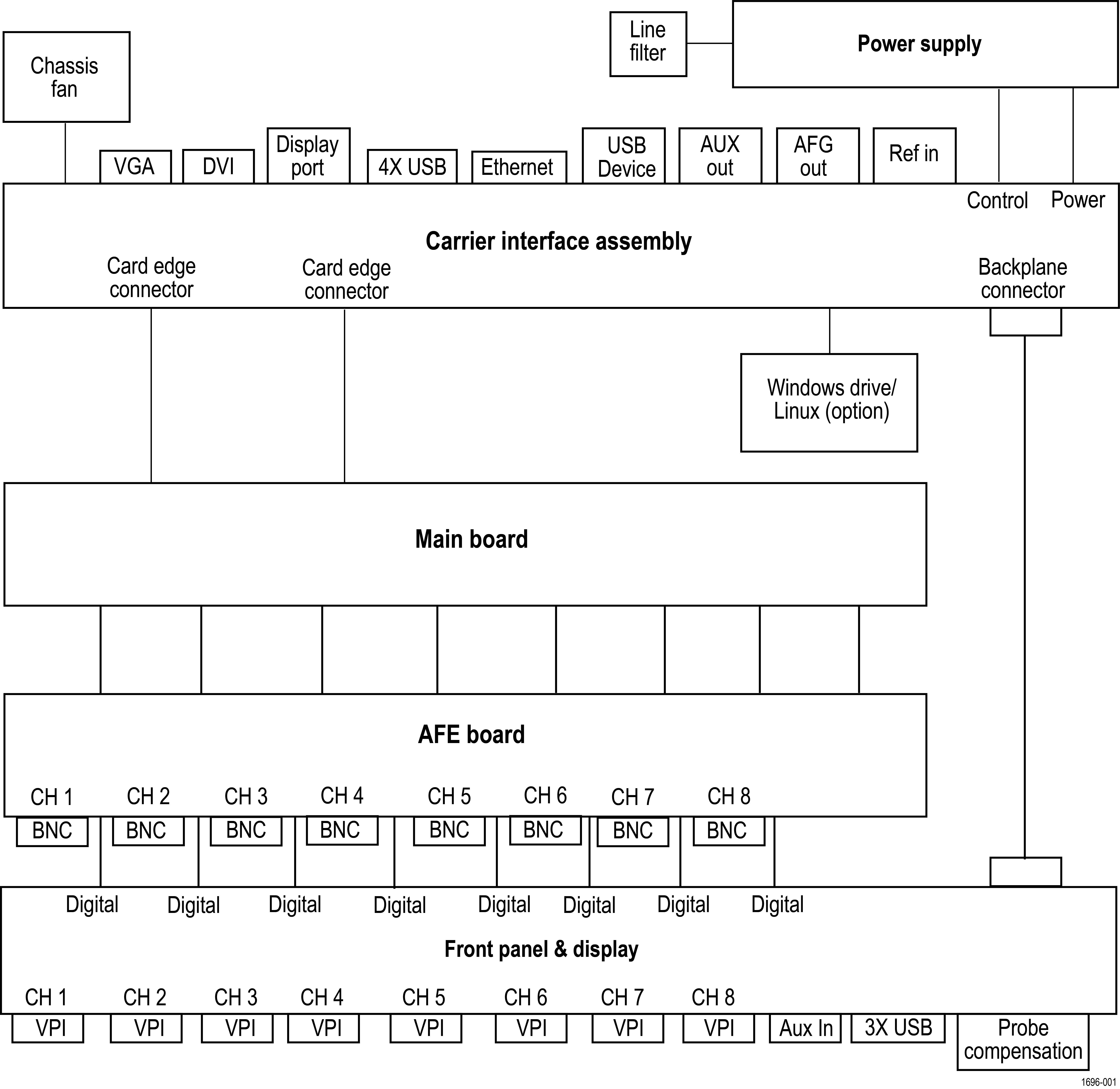
Power supply
The Power Supply board converts AC line voltage to +12 V to power for all internal circuits.
Carrier interface assembly
The Carrier interface assembly contains the following functions:
- Processor system
- The processor system contains a microprocessor that controls the entire instrument. The processor system also contains the solid state drive for the operating system, system RAM, and interfaces to I/O ports and the acquisition system.
- Rear panel I/O ports
- The Carrier interface assembly contains USB ports, an Ethernet port (LAN), a VGA Video port, a DVI Video port, a DisplayPort Video port, the USB-TMC port, an AUX OUT BNC connector, an EXT REF IN BNC connector, and the AFG Out generator BNC connector.
- Power converter
- The Carrier interface assembly converts the +12 V power to all voltages used for the analog and digital circuitry throughout the system. Standby power is used to keep portions of the Carrier interface assembly and Main board powered at all times that AC power is connected to the instrument.
- Other functions
- The Carrier interface assembly also houses the AFG generator, USB-TMC controller and interfaces to the Power supply and various cooling fans. The Carrier interface assembly also provides the interface to the optional Windows drive.
Main board and front-end board
The Main and Analog boards contain the following functions:
- Acquisition system
- The Acquisition system begins with the analog signal path and ends with a digitized signal in memory. The signal enters a channel input, and then passes through an attenuator and preamplifier. The analog signal from each preamplifier goes through a digitizer, and then into acquisition memory. The analog signal from each preamplifier is also distributed to a trigger circuit.
- Front-end
- All of the analog and digital inputs are routed to the Front-end board. The analog channels are amplified and attenuated through the front-end circuitry, and are output to the Main board. The digital channels simply pass through the front-end board to the Main board. The front-end board has a controller that is used as an I/O controller for the front-end board.
- Power converter
- The Main board converts the +12 V power to some of the other voltages used for the analog and digital circuitry throughout the system. This is in addition to the power conversion provided by the Processor assembly.
Front panel and display
The Front Panel board contains digital logic that reads the front-panel buttons and controls and sends this information to the processor system on the Processor assembly. The Front Panel board also generates the probe compensation output signal, provides USB ports on the front panel and houses the main power switch. The front panel routes the digital front-end signals from the probe directly to the front-end board. The front panel also provides the video interface to the internal HD display.
Adjustment procedures
Adjustment and calibration can be performed only by a Tektronix Service Center. See Contacting Tektronix, following the title page in this manual, for information on contacting Tektronix Service Support.
Adjustment interval
The voltage and timing references inside the instrument are very stable over time and do not need routine adjustment.
If the instrument fails the performance tests in the Specifications and Performance Verification manual, adjustment may be required. To download the 6 Series MSO Specification and Performance Verification manual (Tektronix part number 077-1461-XX), go to http://www.tek.com/product-support, enter the manual part number (with no dashes) in the field, click GO, and then select the Specification and Performance Verification document to download.
If your organization requires periodic calibration, a general rule is to verify performance and make adjustments (only if needed) every 2000 hours of operation or once a year if the instrument is used infrequently.
Adjustment after repair
After removal and replacement of any module, you must perform the Performance Verification procedures, found in the Specifications and Performance Verification manual (Tektronix part number 077-1461-XX), available to download from the Tektronix web site (www.tek.com/product-support).
If the instrument fails any Performance Verification tests, it must be returned to a Tektronix Service Center for adjustment and calibration.
Maintenance
Information for periodic and corrective maintenance on the instrument.
Preventing ESD
Before servicing this product, read the General Safety Summary and the Service Safety Summary at the front of the manual, as well as the following ESD information.
| CAUTION:Electrostatic discharge (ESD) can damage any semiconductor component in this instrument.
|
When performing any service that requires internal access to the instrument, adhere to the following precautions to avoid damaging internal modules and their components due to electrostatic discharge:
-
Minimize handling of static-sensitive circuit boards and components.
-
Transport and store static-sensitive modules in their static protected containers or on a metal rail. Label any package that contains static-sensitive boards.
-
Discharge the static voltage from your body by wearing a grounded antistatic wrist strap while handling these modules.
-
Service static-sensitive modules only at a static-free work station.
-
Do not allow any items capable of generating or holding a static charge on the work station surface.
-
Handle circuit boards by the edges when possible.
-
Do not slide the circuit boards over any surface.
-
Avoid handling circuit boards in areas that have a floor or work-surface covering capable of generating a static charge.
Inspection and cleaning
Inspection and Cleaning describes how to inspect for dirt and damage. It also describes how to clean the exterior and interior of the instrument. Inspection and cleaning are done as preventive maintenance. Preventive maintenance, when done regularly, may prevent instrument malfunction and enhance its reliability.
Preventive maintenance consists of visually inspecting and cleaning the instrument and using general care when operating it.
How often to perform maintenance depends on the severity of the environment in which the instrument is used. A proper time to perform preventive maintenance is just before instrument adjustment.
Exterior cleaning (other than display)
Clean the exterior surfaces of the chassis with a dry lint-free cloth or a soft-bristle brush. If any dirt remains, use a cloth or swab dipped in a 75% isopropyl alcohol solution. Use a swab to clean narrow spaces around controls and connectors. Do not use abrasive compounds on any part of the chassis that may damage the chassis.
Clean the On/Standby switch using a cleaning towel dampened with deionized water. Do not spray or wet the switch itself.
| CAUTION:Avoid the use of chemical cleaning agents which might damage the plastics used in this instrument. Use only deionized water when cleaning the front-panel buttons. Use a 75% isopropyl alcohol solution as a cleaner for cabinet parts. Before using any other type of cleaner, consult your Tektronix Service Center or representative.
|
Inspection - Exterior. Inspect the outside of the instrument for damage, wear, and missing parts. Immediately repair defects that could cause personal injury or lead to further damage to the instrument.
| Item | Inspect for | Repair action |
|---|---|---|
| Cabinet, front panel, and cover | Cracks, scratches, deformations, damaged hardware | Repair or replace defective module |
| Front-panel knobs | Missing, damaged, or loose knobs | Repair or replace missing or defective knobs |
| Connectors | Broken shells, cracked insulation, and deformed contacts. Dirt in connectors | Repair or replace defective modules. Clear or brush out dirt |
| Carrying handle and cabinet feet | Correct operation | Repair or replace defective module |
| Accessories | Missing items or parts of items, bent pins, broken or frayed cables, and damaged connectors | Repair or replace damaged or missing items, frayed cables, and defective modules |
Flat panel display cleaning
Clean the flat panel display surface by gently rubbing the display with a clean-room wipe (such as Wypall Medium Duty Wipes, #05701, available from Kimberly-Clark Corporation), or an abrasive-free cleaning cloth.
If the display is very dirty, moisten the wipeor cloth with distilled water, a 75% isopropyl alcohol solution, or standard glass cleaner, and gently rub the display surface. Use only enough liquid to dampen the cloth or wipe. Avoid using excess force or you may damage the display surface.
| CAUTION:Improper cleaning agents or methods can damage the flat panel display.
|
| CAUTION:To prevent getting moisture inside the instrument during external cleaning, do not spray any cleaning solutions directly onto the screen or instrument.
|
Interior cleaning
You can only clean the interior of the rear chassis assembly. To access the rear chassis assembly, see the Removal and Installation Procedures topics.
Do not disassemble or clean the front chassis assembly (other than cleaning the front panel display and removing panel knobs). Disassembling the front chassis assembly requires that the instrument be returned to your nearest Tektronix Service Center for calibration.
| WARNING:To avoid electric shock or damage to the instrument, remove instrument power. Before performing any procedure that follows, power down the instrument and disconnect it from line voltage.
|
- Blow off dust with dry, low-pressure (approximately 9 psi), deionized air.
- Use a soft-bristle, non-static-producing brush for cleaning around components.
- Remove any remaining dust with a lint-free cloth dampened in isopropyl alcohol (75% solution). (A cotton-tipped applicator is useful for cleaning in narrow spaces and on circuit boards).
- If you must use a liquid for minor rear chassis interior cleaning, use a clean-room wipe (such as Wypall Medium Duty Wipes, #05701, available from Kimberly-Clark Corporation) dampened with a 75% isopropyl alcohol solution.
- Inspect the internal portions of the instrument for damage and wear. See Table 1. Defects should be repaired immediately.
- If any circuit board is repaired or replaced, you must perform the Performance Verification procedure in the specifications and performance verification manual, which was provided with your instrument. This manual is also available at www.tektronix.com/manuals, by searching for your product name. If the instrument fails the Performance Verification tests, it must be returned to a Tektronix Service Center for repair and calibration.
| CAUTION:To prevent damage from electrical arcing, ensure that circuit boards and components are dry before applying power to the instrument.
|
| Item | Inspect for | Repair action |
|---|---|---|
| Circuit boards | Loose, broken, or corroded solder connections. Burned circuit boards. Burned, broken, or cracked circuit-run plating. | Remove and replace damaged circuit board. |
| Resistors | Burned, cracked, broken, blistered condition. | |
| Capacitors | Damaged or leaking cases. Corroded solder on leads or terminals. | |
| Wiring and cables | Loose plugs or connectors. Burned, broken, or frayed wiring. | Firmly seat connectors. Replace defective cables. |
| Chassis | Dents, deformations, and damaged hardware. | Straighten, repair, or replace defective hardware. |
Lubrication
There is no periodic lubrication required for this instrument.
Returning the instrument for service
When repacking the instrument for shipment, use the original packaging. If the packaging is unavailable or unfit for use, contact your local Tektronix representative to obtain new packaging.
Seal the shipping carton with an industrial stapler or strapping tape.
Before returning the instrument for service, contact the Service Center to get an RMA (return material authorization) number, and any return or shipping information you may need.
If the instrument is being shipped to a Tektronix Service Center, enclose the following information:
-
The RMA number.
-
The owner's address.
-
Name and phone number of a contact person.
-
Type and serial number of the instrument.
-
Reason for returning.
-
A complete description of the required service.
Mark the address of the Tektronix Service Center and the return address on the shipping carton in two prominent locations.
Removal and replace procedures
This section contains procedures for removal and installation of replaceable modules in the instrument. Refer to Parts ordering information for lists and exploded views of replaceable modules.
Any module inside of the chassis that does not have a remove and replace procedure requires that the entire instrument be returned to Tektronix Service Center for service.
| WARNING:Before performing this or any other procedure in this manual, read the safety summaries found at the beginning of this manual. Also, to prevent possible injury to service personnel or damage to the instrument components, read
Preventing ESD.
Before performing any procedure in this subsection, disconnect the power cord from the line voltage source. Failure to do so could cause serious injury or death. |
| Note:Read the cleaning procedure before disassembling the instrument for cleaning.
|
Required equipment
Most assemblies in this instrument can be removed with a T-10 or T-8 Torx® screwdriver tip.
| Item No. | Name | Description |
|---|---|---|
| 1 | Screwdriver handle | Accepts Torx-driver bits |
| 2 | T-10 Torx tip | Used for removing instrument screws. Torx-driver bit for T-10 size screw heads. |
| 3 | T-8 Torx tip | Used for removing instrument screws. Torx-driver bit for T-8 size screw heads. |
| 4 | 3/16 inch open-end wrench |
Used to remove nut posts. |
| 5 | Proper antistatic work environment | To prevent electrostatic damage to components whenever you work on the instrument, wear properly-grounded electrostatic prevention wrist and foot straps, and work in a tested antistatic environment on an antistatic mat. |
Remove front-panel knobs
Use this procedure to remove and replace front-panel knob assemblies.
Before you begin
- To prevent electrostatic damage to components whenever you work on the instrument, wear properly-grounded electrostatic prevention wrist and foot straps, and work in a tested antistatic environment on an antistatic mat.
About this task
There are eight knob assemblies that can be removed from the front case.
Procedure
- To remove a knob assembly, pull the knob straight out of the front panel. Finger strength is adequate to pull knobs. Do not use pliers.
- To reinstall a knob, align the knob with the shaft indent and press the knob onto the shaft. Turn the knob to make sure there is a smooth rotation.
Remove SATA riser board assembly
Use this procedure to remove and replace the external hard drive SATA riser board assembly.
Before you begin
- To prevent electrostatic damage to components whenever you work on the instrument, wear properly-grounded electrostatic prevention wrist and foot straps, and work in a tested antistatic environment on an antistatic mat.
About this task
Procedure
- Set instrument on its back, with the bottom facing you.
- Open and remove the hard drive door from the bottom of the instrument.
- Remove the three T-10 Torx screws securing the SATA riser board bracket assembly to the chassis.
- Remove the SATA riser board bracket assembly from bottom of chassis.
- To remove the SATA riser board, remove the two T-10 Torx screws securing the SATA riser board to the riser bracket.
- To reinstall, reverse the steps. Tighten the T-10 Torx screws to 0.65 N·m.
Remove feet
Use this procedure to remove and replace bottom feet assemblies or gain access to the rear chassis assembly.
Before you begin
- To prevent electrostatic damage to components whenever you work on the instrument, wear properly-grounded electrostatic prevention wrist and foot straps, and work in a tested antistatic environment on an antistatic mat.
About this task
Remove the two flip feet assemblies from the rear chassis using the following steps:
Procedure
- Remove all cables and the power cord from the rear panel.
- Set the instrument on its back side so the bottom is facing you.
- Flip open both feet assemblies.
- Use a screwdriver with T-10 Torx tip to remove the four screws from each foot assembly.
- Remove the feet assembles.
- To reinstall, reverse the steps. Use a screwdriver with T-10 Torx tip to secure the eight screws. First insert and tighten the screws that are near the front edge of the instrument, then insert and tighten the screws that are near the rear edge of the instrument. Tighten to 0.65 N·m.
Remove handle
Use this procedure to remove and replace the handle assemblies.
Before you begin
- To prevent electrostatic damage to components whenever you work on the instrument, wear properly-grounded electrostatic prevention wrist and foot straps, and work in a tested antistatic environment on an antistatic mat.
About this task
Remove the handle assemblies using the following steps:
Procedure
- Use a screwdriver with T-10 Torx tip to remove two screws from each side of the handle.
- Disengage the handle from the pins on the couplers and remove the handle.
- Remove the two couplers.
- To reinstall, reverse the steps. Use a screwdriver with T-10 Torx tip to secure the screws. Tighten to 0.65 N·m.
Remove rear grill and case
Use this procedure to remove and replace the rear grill and rear case.
Before you begin
- To prevent electrostatic damage to components whenever you work on the instrument, wear properly-grounded electrostatic prevention wrist and foot straps, and work in a tested antistatic environment on an antistatic mat.
- Remove handle.
- Remove feet.
- Remove hard drive door.
About this task
Remove the grill and rear case using the following steps:
Procedure
- Use a screwdriver with T-8 Torx tip to remove the six screws securing the grill to the rear case .
- Put fingers in handle hub holes on each side of the grill and pull the grill off of the rear case.
- Use a screwdriver with T-10 Torx tip to remove the six screws securing the rear case to the rear chassis .
- Slide the rear case off of the rear chassis.
- To reinstall, reverse the steps. Tighten the six T-10 Torx rear case screws to 0.65 N·m. Tighten the six T-8 Torx rear grill screws to 0.45 N·m.
Remove rear chassis assembly
Use this procedure to remove and replace the rear chassis, to access rear chassis assemblies (power supply, main fan, Carrier interface assembly, AFG Riser board).
Before you begin
- To prevent electrostatic damage to components whenever you work on the instrument, wear properly-grounded electrostatic prevention wrist and foot straps, and work in a tested antistatic environment on an antistatic mat.
- Remove rear grill and case
About this task
Remove the rear chassis assembly from the front chassis assembly using the following steps:
Procedure
- Place the instrument face down on a soft surface or fixture.
 CAUTION:Place the instrument face down carefully to prevent damage to the knobs.
 - Insert a large flat blade screwdriver no more than 1/4 inch into a rectangular slot on the corner of the rear chassis (see following image). Rotate the screwdriver to lift the corner of the rear chassis from the front chassis. Repeat on each corner. There may be a little resistance from the front right corner of the bottom edge, where the rear chassis interconnects to the front chassis.

Remove the baffle bracket
Use this procedure to remove and replace the baffle bracket from the rear chassis, to gain access to the power supply assembly.
Before you begin
- To prevent electrostatic damage to components whenever you work on the instrument, wear properly-grounded electrostatic prevention wrist and foot straps, and work in a tested antistatic environment on an antistatic mat.
- Remove rear chassis assembly
Procedure
- Set the rear chassis with the rear side down.
CAUTION:Position the chassis carefully to prevent damage to the BNCs.
- Remove the
twelve
T-10 Torx screws from the baffle bracket.

Remove the power supply assembly
Use this procedure to remove and replace the power supply assembly.
Before you begin
- To prevent electrostatic damage to components whenever you work on the instrument, wear properly-grounded electrostatic prevention wrist and foot straps, and work in a tested antistatic environment on an antistatic mat.
- Remove the baffle bracket
About this task
Procedure
- Disconnect the cables connecting the power supply to the carrier interface assembly, AFG riser board, and AC line filter.
- Use a
T-10 Torx bit screwdriver to remove the four screws securing the power supply assembly to the chassis. Tighten screws to 0.65 N·m when reinstalling.
- Disconnect the three power supply cables from the power supply board.
- Use a
T-10 Torx bit screwdriver to remove the seven screws securing the power supply board to the power supply bracket.
- To reinstall, reverse the steps. Tighten all
T-10 Torx screws to 0.65 N·m when reinstalling. Make sure black cables dress cleanly through the side slot, and do not get pinched between the power supply bracket and rear chassis when reinstalling the power supply assembly. Install new tie down straps (zip ties) if you removed them during disassembly.
Note:Make sure to properly align the power supply board with the power supply shield before securing the board to the power supply bracket.


Remove carrier interface assembly
Use this procedure to remove and replace the carrier interface assembly, which contains the AFG Riser assembly and the M.2 SSD memory board with the system OS. Only use this procedure to sanitize the instrument before sending for repairs at a Tektronix Service Center.
Before you begin
- To prevent electrostatic damage to components whenever you work on the instrument, wear properly-grounded electrostatic prevention wrist and foot straps, and work in a tested antistatic environment on an antistatic mat.
- Remove SATA riser board assembly
- Remove rear chassis assembly
- Remove the baffle bracket
Procedure
- Use a
T-10 Torx screwdriver to remove the screw between the BNC connectors on the rear panel of the chassis. Use a 3/16-inch open end wrench to remove the four jack screws from the video connectors on the rear panel.
- Disconnect the black cables connecting the power supply to the carrier interface assembly and the white cable on the AFG riser board. You do not need to disconnect the AC line filter cables.
-
Disconnect fan cables.
- Use a
T-10 Torx screwdriver to remove the eight screws on the bottom of the chassis.
- Use a
T-8 Torx screwdriver to remove the two screws on the top front edge of the of the carrier interface chassis.


Remove the AFG riser assembly
Use this procedure to remove and replace the AFG riser assembly from the carrier interface assembly. Only use this procedure as part of the sanitize process before sending the instrument for repairs at a Tektronix Service Center.
Before you begin
- To prevent electrostatic damage to components whenever you work on the instrument, wear properly-grounded electrostatic prevention wrist and foot straps, and work in a tested antistatic environment on an antistatic mat.
- Remove carrier interface assembly. The carrier interface assembly must be removed from the rear chassis before removing the AFG riser assembly. There is not enough clearance for the BNC and video connectors to remove the assembly while it is installed in the chassis.
Procedure
- Use a
T-10 Torx screwdriver to remove the one screw on the AFG riser assembly bracket.

Remove handle hub assembly
Use this procedure to remove and replace the handle hubs from the rear chassis. You will need to remove the left side hub if you want to remove the main fan.
Before you begin
- To prevent electrostatic damage to components whenever you work on the instrument, wear properly-grounded electrostatic prevention wrist and foot straps, and work in a tested antistatic environment on an antistatic mat.
- Remove rear chassis assembly
- Remove the baffle bracket
Procedure
- Remove the left and right handle hub assemblies from the inside walls of the chassis using a T-10 Torx bit screwdriver. Two screws will be removed for each hub assembly.
- To reinstall, reverse the steps. Use a screwdriver with a T-10 Torx tip to tighten the screws to 0.65 N·m.
Remove the main fan assembly
Use this procedure to remove and replace the main fan from the rear chassis.
Before you begin
- To prevent electrostatic damage to components whenever you work on the instrument, wear properly-grounded electrostatic prevention wrist and foot straps, and work in a tested antistatic environment on an antistatic mat.
- Remove the baffle bracket
- Remove handle hub assembly next to the main fan
- Remove carrier interface assembly
Procedure
- Use a
T-10 Torx screwdriver
to remove the eight screws from the main fan assembly bracket and rear chassis.

Troubleshooting 6 Series MSO
| CAUTION:Before performing this or any other procedure in this manual, read the General Safety Summary and Service Safety Summary found at the beginning of this manual.
To prevent possible injury to service personnel or damage to electrical components, please read information on Preventing ESD. (See Preventing ESD.) |
This section contains information and procedures designed to help you isolate faults to a module.
This section requires that service personnel have the appropriate skills to work on this instrument, including PC troubleshooting and Microsoft Windows operating system skills. Details of PC and Windows operation and service are not in this manual.
For assistance, contact your local Tektronix Service Center.
Service level
This subsection contains information and procedures to help you determine if a faulty power supply is the problem with your instrument. If replacing the power supply does not fix the fault, you will need to return the instrument to a Tektronix Service Center for repair, as no other internal electronic assemblies or modules are user-replaceable.
Check for common problems
Use the following table to help isolate possible failures. The table lists problems and possible causes. The list is not exhaustive, but it may help you eliminate a problem that is quick to fix, such as a loose power cord. For more detailed troubleshooting, see the Troubleshooting flow chart.
| Symptom | Possible cause(s) |
|---|---|
|
Instrument will not power on |
|
|
Instrument powers on, but one or more fans will not operate |
|
|
Instrument doesn't boot up |
|
|
Flat-panel display blank or has streaks in display |
|
Equipment required
- Digital voltmeter to check power supply voltages.
- 0.1 inch spacing 2-pin jumper.
- An antistatic work environment. To prevent electrostatic damage to components whenever you work on the instrument, wear properly-grounded electrostatic prevention wrist and foot straps, and work in a tested antistatic environment on an antistatic mat.
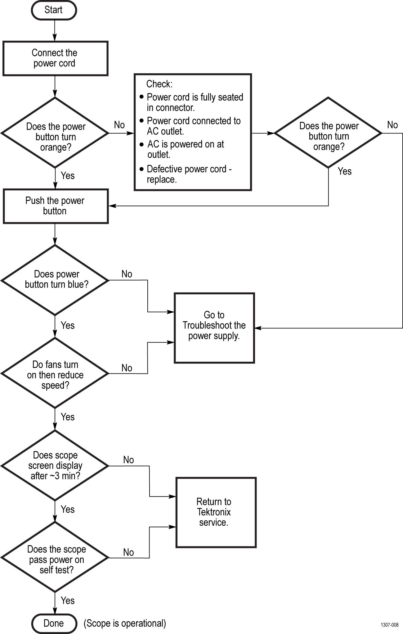
Troubleshooting flow chart
Follow the troubleshooting flow chart to determine the action for a fault condition.
Status LEDs. A set of six bi-color LEDs report the power management status of the instrument. These LEDs are located under the cover on the bottom of the instrument.
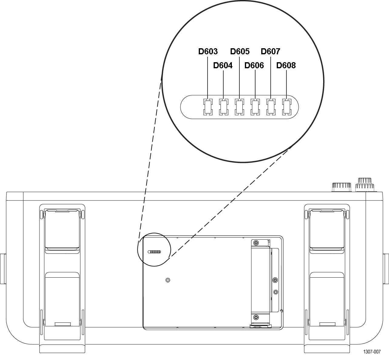
| Note:Before you send the instrument to Tektronix for repair, make sure that each LED status is recorded and attached the recordsheet with the instrument. |
Troubleshoot the power supply
Use this procedure to determine if the power supply is defective and needs replaced.
Before you begin
- To prevent electrostatic damage to components whenever you work on the instrument, wear properly-grounded electrostatic prevention wrist and foot straps, and work in a tested antistatic environment on an antistatic mat.
- Remove rear chassis assembly
- Remove the baffle bracket
Procedure
- Measure for
+12 V
DC
between chassis and pin 10 of J3203 (large connector). If there is +12 VDC at pin 10, go to step
3. If you do not measure +12 VDC at Pin 10 of J3203 connected to the circuit board:
- Measure for
+12 V
DC
between pin 10 (+12 VDC) and pin 18 (ground) on the disconnected cable.
If there is no +12 VDC value on pin 10, carefully check for 115 V AC at the connectors of the AC line filter. If there is AC at the line filter, replace the power supply module or reassemble and return the instrument to a Tektronix Service Center for repair.WARNING:Be careful when measuring the AC line voltage to avoid injury to yourself or damage to the instrument.
- Measure for
+12 V
DC
between pin 10 (+12 VDC) and pin 18 (ground) on the disconnected cable.
- If there is
+12 V
DC
at pin 10 of the disconnected J3203 cable, do the following:
- Insert for one (1) second and then remove a 0.1-inch-spaced shorting jumper between pins 9 and 10 of the Service connecter pins on the edge of the circuit board (see following image). Wait five (5)seconds as the fans turn on and the power supply powers on.
- Insert for one (1) second and then remove a 0.1-inch-spaced shorting jumper between pins 9 and 10 of the Service connecter pins on the edge of the circuit board (see following image). Wait five (5)seconds as the fans turn on and the power supply powers on.


Instrument self tests
The instrument runs self test diagnostics during every power on. The power on self tests ensure that the hardware and software are functionally working. The tests provide limited diagnostic information, and provide no performance information.
If the instrument detects errors during power on, a pop-up message indicates that a failure has occurred. To display the Self test menu and results, select Utility > Self Test. Select a test mode and run the self tests. If you continue to get errors on one or more tests, you will need to return the instrument to your nearest Tektronix Service Center for repair.
Export log files
Log files are useful by Tektronix in troubleshooting the instrument.
- Insert a USB drive into a front panel USB Host port.
- Tap Utility > Self Test > Export Log Files and select the USB drive from the displayed menu.
- Tap OK.
- At the end of the save operation, remove the USB drive.
Download and install the latest instrument firmware
Installing the latest firmware helps ensure that your instrument has the lastest features and is taking the most accurate measurements.
Before you begin
Save any important on-instrument files (waveforms, screen captures, setups, and so on) to a USB drive or network. The installation process does not remove user-created files, but it is a good idea to back up important files before an update.
Determine the current version of firmware installed on the instrument (see Help > About).
Update instrument firmware from a USB drive
Procedure
- To install firmware on standard instruments:
- Power on the instrument and wait for the instrument to fully boot up.
- Insert the USB flash drive into any instrument USB Host port.
- The instrument detects the update firmware and opens a dialog box. Follow the on-screen instructions to install the firmware.
Note:Do not power off the instrument or remove the USB flash drive until the instrument finishes installing the firmware. The instrument displays a message when it is OK to power off. Remove the USB drive before powering on the instrument. - To install firmware on instruments with the Windows option:
- Close the TekScope program before updating the firmware.
- Insert the USB drive into any instrument USB Host port.
- Open the Windows desktop File Explorer and navigate to and select the install file.
- Run the firmware update file from the USB drive, or copy the firmware update file to the desktop and run the file from there.
- Follow any on-screen instructions to install the firmware.
- When the firmware install is finished, remove the USB drive and restart the instrument.
Note:Do not power off the instrument, or remove the USB flash drive if installing from the drive, until the instrument finishes installing the firmware. The instrument displays a message when it is OK to power off.
After power supply module replacement
After removal and replacement of the power supply module, you must perform the Performance Verification procedures, found in the Specifications and Performance Verification manual (Tektronix part number 077-1461-xx). Download this manual from the Tektronix Web site (www.tek.com/manuals).
If the instrument fails the Performance Verification tests, it must be returned to a Tektronix Service Center for adjustment.
Replaceable parts list
This section contains a list of the replaceable assemblies for the instrument. Use this list to identify and order replacement parts
Parts ordering information
Use the lists in the appropriate section to identify and order replacement parts for your product. Replacement parts are available through your local Tektronix field office or representative.
Standard accessories for these products are listed in your user manual. The user manual is available at www.tek.com/manuals.
Changes to Tektronix products are sometimes made to accommodate improved components as they become available and to give you the benefit of the latest improvements. Therefore, when ordering parts, it is important to include the following information in your order:
-
Part number
-
Instrument type or model number
-
Instrument serial number
-
Instrument modification number, if applicable
If you order a part that has been replaced with a different or improved part, your local Tektronix field office or representative will contact you concerning any change in part number.
Module servicing
Modules can be serviced by selecting one of the following three options. Contact your local Tektronix Service Center or representative for repair assistance.
Module exchange. In some cases, you may exchange your module for a remanufactured module. These modules cost significantly less than new modules and meet the same factory specifications. For more information about the module exchange program, call 1-800-833-9200. Outside North America, contact a Tektronix sales office or distributor; see the Tektronix Web site (www.tek.com) for a list of offices.
Module repair and return. You may ship your module to us for repair, after which we will return it to you.
New modules. You may purchase replacement modules in the same way as other replacement parts.
Abbreviations
Abbreviations conform to American National Standard ANSI Y1.1-1972.
Using the replaceable parts list
This section contains a list of the replaceable mechanical and/or electrical components. Use this list to identify and order replacement parts. The following table describes each column in the parts list.
Parts list column descriptions
| Column | Column name | Description |
|---|---|---|
| 1 | Figure & index number | Items in this section are referenced by figure and index numbers to the exploded view illustrations that follow. |
| 2 | Tektronix part number | Use this part number when ordering replacement parts from Tektronix. |
| 3 and 4 | Serial number | Column three indicates the serial number at which the part was first effective. Column four indicates the serial number at which the part was discontinued. No entry indicates the part is good for all serial numbers. |
| 5 | Qty | This indicates the quantity of parts used. |
| 6 | Name & description | An item name is separated from the description by a colon (:). Because of space limitations, an item name may sometimes appear as incomplete. Use the U.S. Federal Catalog handbook H6-1 for further item name identification. |
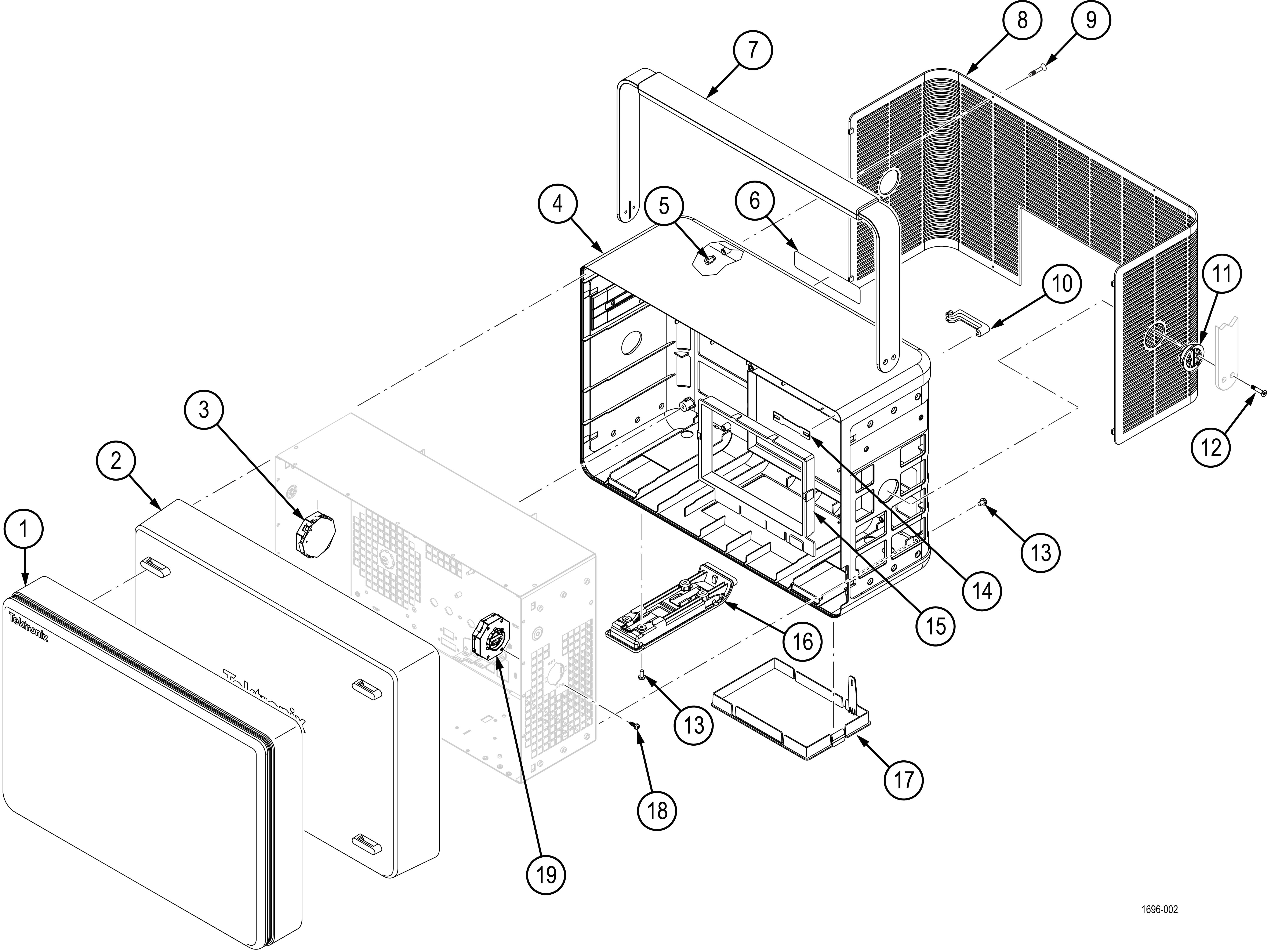
Front cover and rear case
| Index number | Tektronix part number | Serial no. effective | Serial no. discont'd | Qty | Name & description |
|---|---|---|---|---|---|
| Figure 1 | |||||
| -1 | 016-2106-XX | 1 | CASE, ACCESSORY FRONT COVER | ||
| -2 | 200-5406-XX | 1 | COVER, FRONT PROTECTIVE | ||
| -3 | 050-3895-XX | 1 | KIT;MSO5 SERIES HANDLE HUB LEFT | ||
| -4 | 065-1007-XX | 1 | MODULE ASSY:SERVICE REPLACEMENT KIT;REAR CASE W/ POWER SPRING CLIPS AND STAND-OFFS; SAFETY CONTROLLED | ||
| -5 | 220-0325-XX | 6 | INSERT, 2.5MM, SNAP IN | ||
| -6 | 335-3850-XX | 1 | MARKER, IDENTIFICATION, SERVICE US PLUS, ENGLISH | ||
| 335-3851-XX | 1 | MARKER, IDENTIFICATION, SERVICE EUROPE, ENGLISH | |||
| 335-3852-XX | 1 | MARKER, IDENTIFICATION, SERVICE JAPAN, JAPANESE | |||
| 335-3853-XX | 1 | MARKER, IDENTIFICATION, SERVICE CHINA, SIMPLIFIED CHINESE | |||
| 335-3854-XX | 1 | MARKER, IDENTIFICATION, SERVICE OTHER, ENGLISH | |||
| -7 | 050-3904-XX | 1 | KIT:SERVICE REPLACEMENT KIT;METAL HANDLE W/PLASTIC GRIP AND HARDWARE;MSO5 & MSO6 SERIES | ||
| -8 | 378-0952-XX | 1 | GRILL, COSMETIC, REAR, SAFETY CONTROLLED | ||
| -9 | 211-1573-XX | 6 | SCREW, CAPTIVE; M2.5 X .45 X 14 FLAT HEAD, TORX T8, W/ DOGPOINT | ||
| -10 | 105-1186-XX | 2 | HOOK, CORD WRAP, SAFETY CONTROLLED | ||
| -11 | 376-0256-XX | 2 | COUPLER, HUB HANDLE, SAFETY CONTROLLED | ||
| -12 | 211-1610-XX | 4 | SCREW, MACHINE; M3 X 0.5 X 16, FLAT HEAD, STL, TORX 10 | ||
| -13 | 211-1584-XX | 12 | SCREW, MACHINE, M3 X 0.5 X 6MM PAN HEAD, TORX T10 | ||
| -14 | 214-5384-XX | 2 | SPRING, CORD WRAP | ||
| -15 | 437-0544-XX | 1 | TRIM, REAR I/O | ||
| -16 | 065-1008-XX | 2 | MODULE ASSY: SERVICE REPLACEMENT KIT; FLIP FEET | ||
| -17 | 200-5339-XX | 1 | DOOR, HARD DRIVE | ||
| -18 | 211-1585-XX | 5 | SCREW, DELTA-PT, 3MM X 8MM, T10 | ||
| -19 | 050-3896-XX | 1 | KIT;MSO5 SERIES HANDLE HUB RIGHT | ||
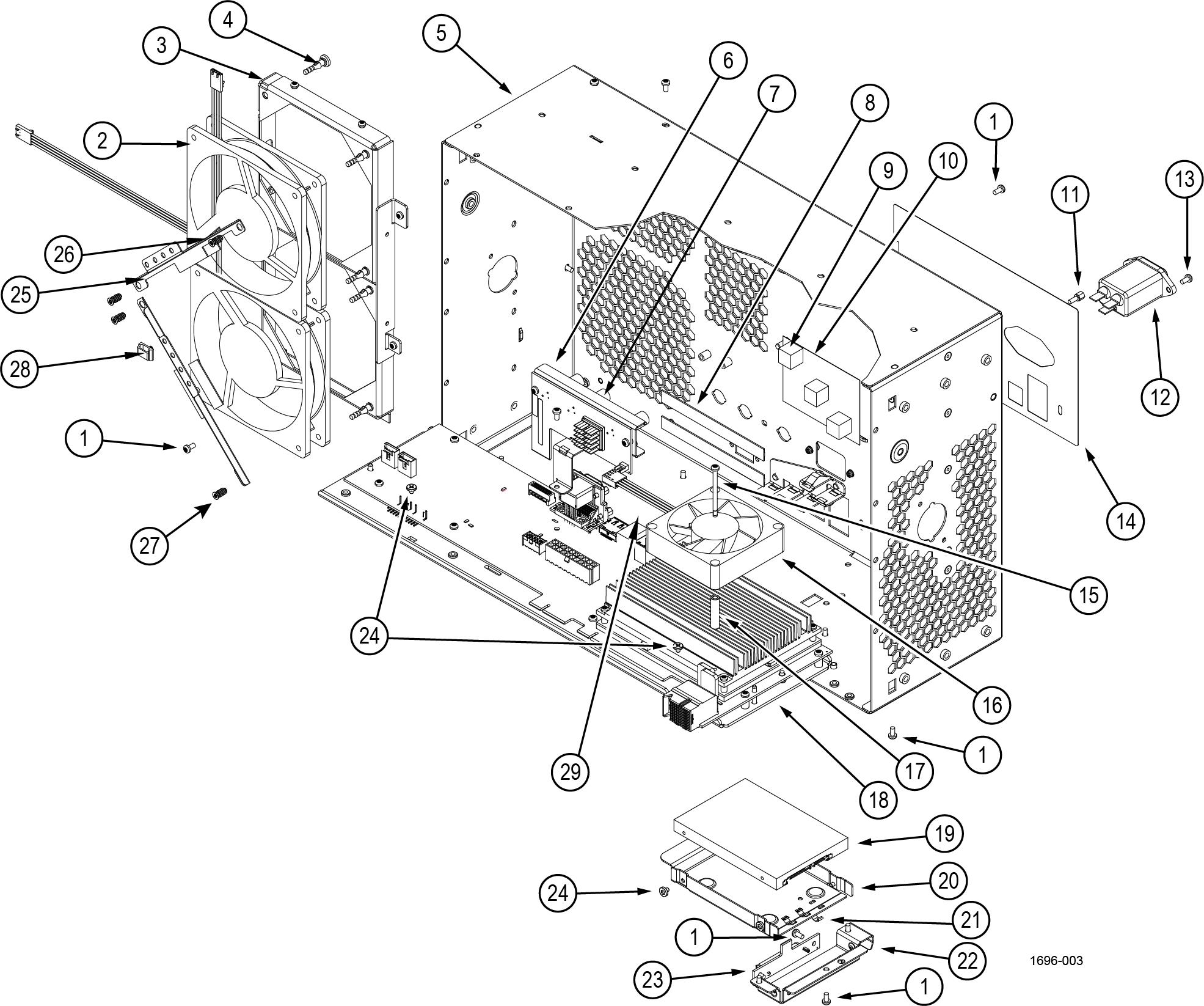
Carrier interface board and rear chassis
| Index number | Tektronix part number | Serial no. effective | Serial no. discont'd | Qty | Name & description |
|---|---|---|---|---|---|
| Figure 1 | |||||
| -1 | 211-1584-XX | 20 | SCREW, MACHINE, M3 X 0.5 X 6MM PAN HEAD, TORX T10 | ||
| -2 | 119-9200-XX | 2 | FAN ASSEMBLY, 119919900 WITH TERMINATION, SAFETY CONTROLLED | ||
| -3 | 407-6063-XX | 1 | BRKT, 120MM X 38MM FAN, SAFETY CONTROLLED | ||
| -4 | 348-2082-XX | 4 | GROMMET, FAN MOUNT, NOISE DAMPING | ||
| -5 | 441-2893-XX | 1 | CHASSIS, REAR, SAFETY CONTROLLED | ||
| -6 | 878-1143-XX | 1 | CIRCUIT BOARD SUBASSY; AFG RISER BOARD UNTESTED; 389494600 Return the instrument to Tektronix for service. | ||
| -7 | 348-2287-XX | 3 | GASKET, EMI, BNC 5.00MM THICK | ||
| -8 | 348-2264-XX | 2 | GASKET, CONDUCTIVE, FOF, 1MM X 10MM X 100MM | ||
| -9 | 337-4885-XX | 1 | SHIELD, INSULATOR, POWER SUPPLY AND POSITIONER | ||
| -10 | 348-2350-XX | 3 | BUMPER, DAMPER; PAD | ||
| -11 | 214-3903-XX | 4 | SCREW, JACK; 4-40 X 0.312 LONG, 0.188 HEX HEAD STAND OFF W/ ASSEMBLED SPLIT LOCK WASHER, 4-40 INT THD, X 0.312 THD EXT 4-40, STEEL, ZINC PLATED | ||
| -12 | 119-8742-XX | 1 | FILTER, EMI; AC LINE FILTER; 10.0A,120-250VAC, DC-400 HZ, IEC INPUT ,FAST-ON/SOLDER LUG OUTPUT, CHASSIS MOUNT; FN9244R10-06; SAFETY CONTROLLED | ||
| -13 | 211-1686-XX | 2 | SCREW, MACHINE, M3 X 0.5 X 10 FLATHEAD, 90 DEG, BLACK ZINC,TUFLOK, TORX T10 | ||
| -14 | 335-4459-XX | 1 | LABEL, REAR, IO | ||
| -15 | 211-1571-XX | 4 | SCREW, MACHINE, M3 X 0.5 X 40MM PAN HEAD, TORX T8 WITH NYLON PATCH | ||
| -16 | 119-8639-XX | 1 | FAN ASSEMBLY,119864000 W / TERMINATION, SAFETY CONTROLLED | ||
| -17 | 361-1883-XX | 4 | SPACER, RND, 6MM OD X 3.2MM ID X 25MMLG | ||
| -18 | 065-1064-XX | 1 | MODULE ASSY;SERVICE REPLACEMENT; 8781722XX CARRIER BOARD ASSY AND COM-E 0390232XX, TESTED AND PROGRAMMED, MSO6XB Return the instrument to Tektronix for service. | ||
| -19 | 065-1075-XX | 1 | MODULE ASSY;SERVICE REPLACEMENT;1198773XX 256GB SSHD, UNPROGRAMMED W/ MECHANICALS, MSO6XB | ||
| 065-1074-XX | 1 | MODULE ASSY;SERVICE REPLACEMENT;1198250XX 512GB SSHD, UNPROGRAMMED W/ MECHANICALS, MSO6XB FOR WIN & LNX | |||
| -20 | 407-5877-XX | 1 | BRACKET, HARDDRIVE | ||
| -21 | 131-6643-XX | 3 | CONTACT, ELECTRICAL | ||
| -22 | 407-5896-XX | 1 | BRACKET, SATA RISER | ||
| -23 | 878-1100-XX | 1 | CIRCUIT BOARD SUBASSY; SATA RISER CARD; UNTESTED; 389491600 | ||
| -24 | 211-1631-XX | 6 | SCREW, MACHINE, M3-0.5, 3.5L, T8 (UNDER HEAD SERRATIONS) | ||
| -25 | 407-6124-XX | 2 | BRACKET, SUPPORT FAN, GNM 407612400 | ||
| -26 | 348-1972-XX | 2 | GASKET, URETHANE W ADHESIVE | ||
| -27 | 213-1150-XX | 4 | SCREW, FLAT HEAD, T15 FAN SCREW, M5X10 | ||
| -28 | 343-1778-XX | 1 | CLAMP, CABLE; HOLE MOUNT | ||
| -29 | 337-4804-XX | 1 | SHIELD, LAN PORT | ||
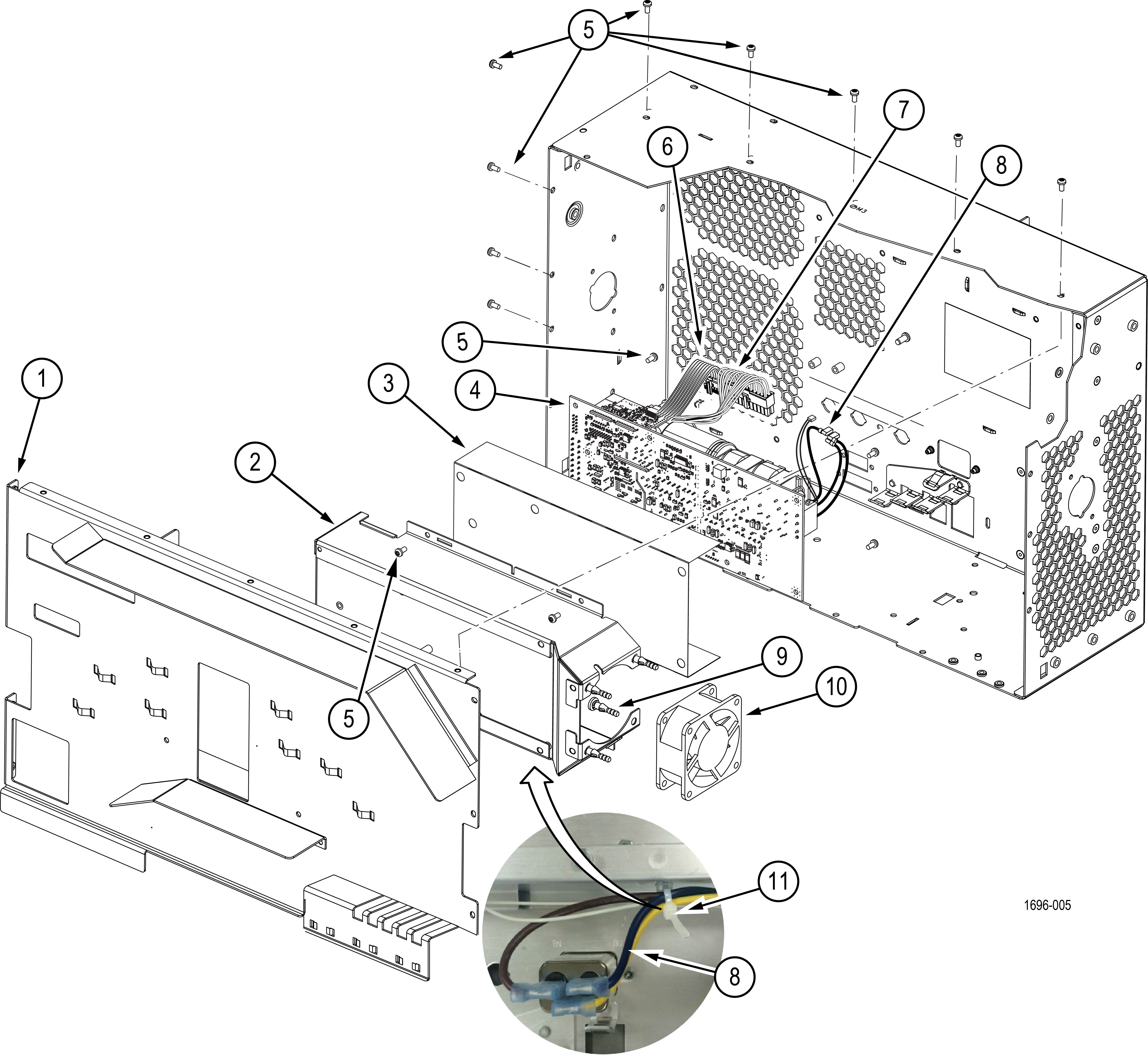
Baffle and power supply module
| Index number | Tektronix part number | Serial no. effective | Serial no. discont'd | Qty | Name & description |
|---|---|---|---|---|---|
| Figure 1 | |||||
| -1 | 407-6221-XX | 1 | BRACKET, BAFFLE, SINGLE FAN, HYBRID | ||
| -2 | 407-6076-XX | 1 | BRACKET, POWER SUPPLY, 750W, SAFETY CONTROLLED | ||
| -3 | 337-4717-XX | 1 | SHIELD, MOUNT, POWER SUPPLY, SAFETY CONTROLLED | ||
| -4 | 119-8375-XX | 1 | POWER SUPPLY; INTERNAL, AC-DC; 90-264VAC 47-63HZ, 103-127VAC 360-440HZ IN; +12V 44A, +12VSB 1.25A OUT; I2C, PSON, ACOK, PWRGOOD SIGNALS; SAFETY CONTROLLED, SAFETY CONTROLLED Return the instrument to Tektronix for service. | ||
| -5 | 211-1584-XX | 20 | SCREW, MACHINE, M3 X 0.5 X 6MM PAN HEAD, TORX T10 | ||
| -6 | 174-6612-XX | 1 | CABLE, POWER, PWR SUP TO CARRIER, SAFETY CONTROLLED | ||
| -7 | 174-6613-XX | 1 | CABLE, PS TO CARRIER, SIGNALS (2X6 DISCRETE, .100 CTRS, LATCHING), SAFETY CONTROLLED | ||
| -8 | 174-6614-XX | 1 | CABLE ASSEMBLY (LINE INPUT), SAFETY CONTROLLED | ||
| -9 | 348-2082-XX | 4 | GROMMET, FAN MOUNT, NOISE DAMPING | ||
| -10 | 119-8397-XX | 1 | FAN WITH 2X2 CONN, 60X25MM, 12V, SAFETY CONTROLLED | ||
| -11 | 343-0549-XX | 1 | STRAP, TIEDOWN; 0.098 W X 4.0 L, ZYTEL | ||
Mid-plane chassis
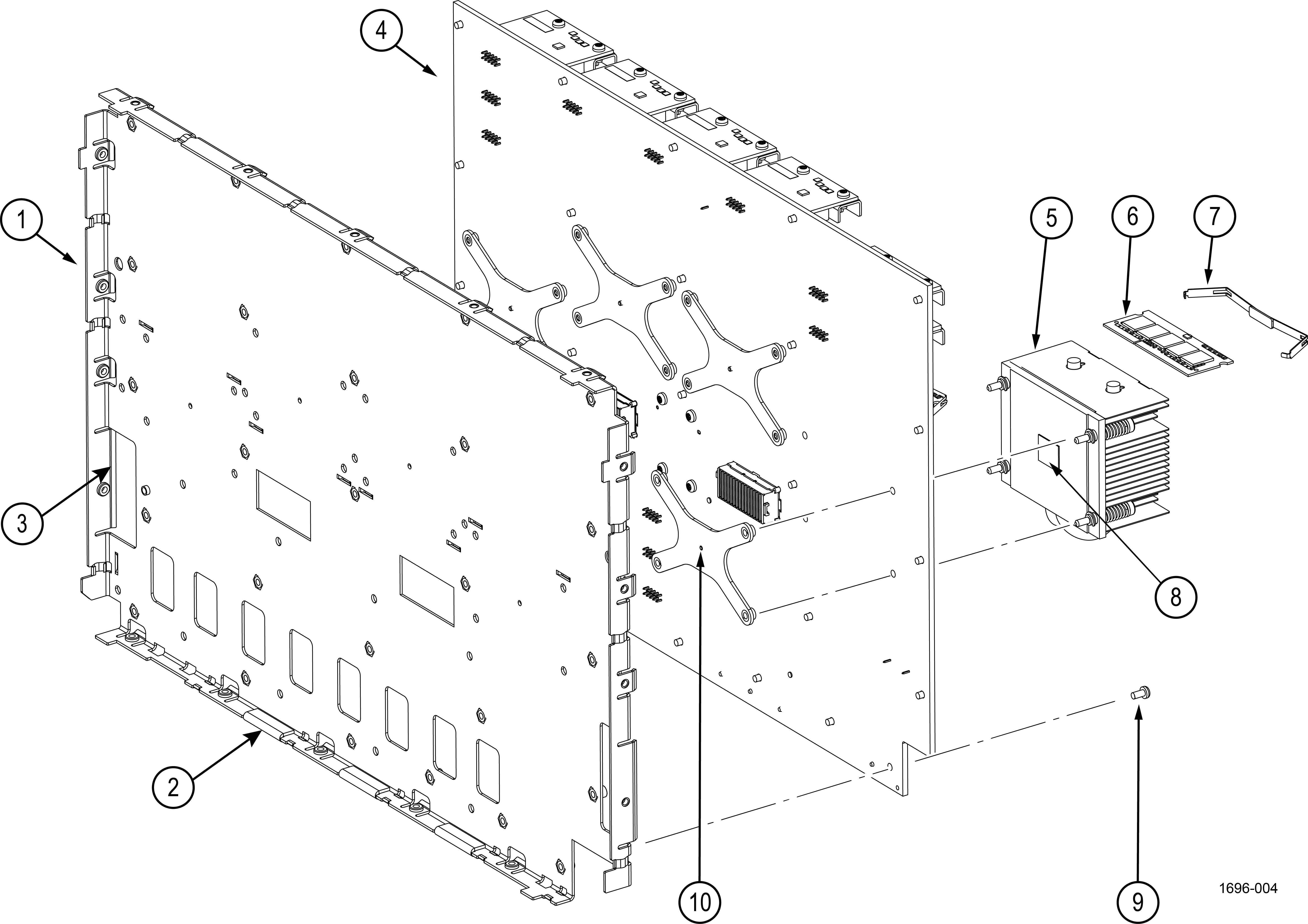
| Note:None of the components listed are user-replaceable. Return the instrument to your nearest Tektronix Service Center to repair or replace any internal components or assemblies in this diagram. |
| Index number | Tektronix part number | Serial no. effective | Serial no. discont'd | Qty | Name & description |
|---|---|---|---|---|---|
| Figure 1 | |||||
| -1 | 441-2927-XX | 1 | ASSEMBLY, CHASSIS, MID-PLANE Return the instrument to Tektronix for service. | ||
| -2 | 348-2298-XX | 4 | GASKET, CONDUCTIVE FOAM W/PSA 12MM X 29MM X 1.5MM THICK | ||
| -3 | 348-2361-XX | 1 | GASKET, CONDUCTIVE FOF WITH ELECTRICALLY CONDUCTIVE PSA | ||
| -4 | 870-1386-XX | 1 | CIRCUIT BRD ASSY;MAIN, 8781386XX TESTED WITH PACKAGING, MSO6XB Return the instrument to Tektronix for service. | ||
| -5 | 214-5483-XX | 1 | HEATSINK, HEATPIPE Return the instrument to Tektronix for service. | ||
| -6 | 167-4126-XX | 8 | IC, MEMORY, DRAM;DDR3, , 2GB 256MX72, DDR3-1866, ECC, SODIMM 204 Return the instrument to Tektronix for service. | ||
| -7 | 407-5956-XX | 8 | BRACKET, SO-DIMM RETENTION, ASSEMBLY Return the instrument to Tektronix for service. | ||
| -8 | 253-0559-XX | 1 | THERMAL INTERFACE MATERIAL, TEK049 Return the instrument to Tektronix for service. | ||
| -9 | 211-1584-XX | 20 | SCREW, MACHINE, M3 X 0.5 X 6MM PAN HEAD, TORX T10 | ||
| -10 | 386-7847-XX | 2 | HEATSINK BACKER ASSEMBLY; TEK049 Return the instrument to Tektronix for service. | ||
Front panel and display
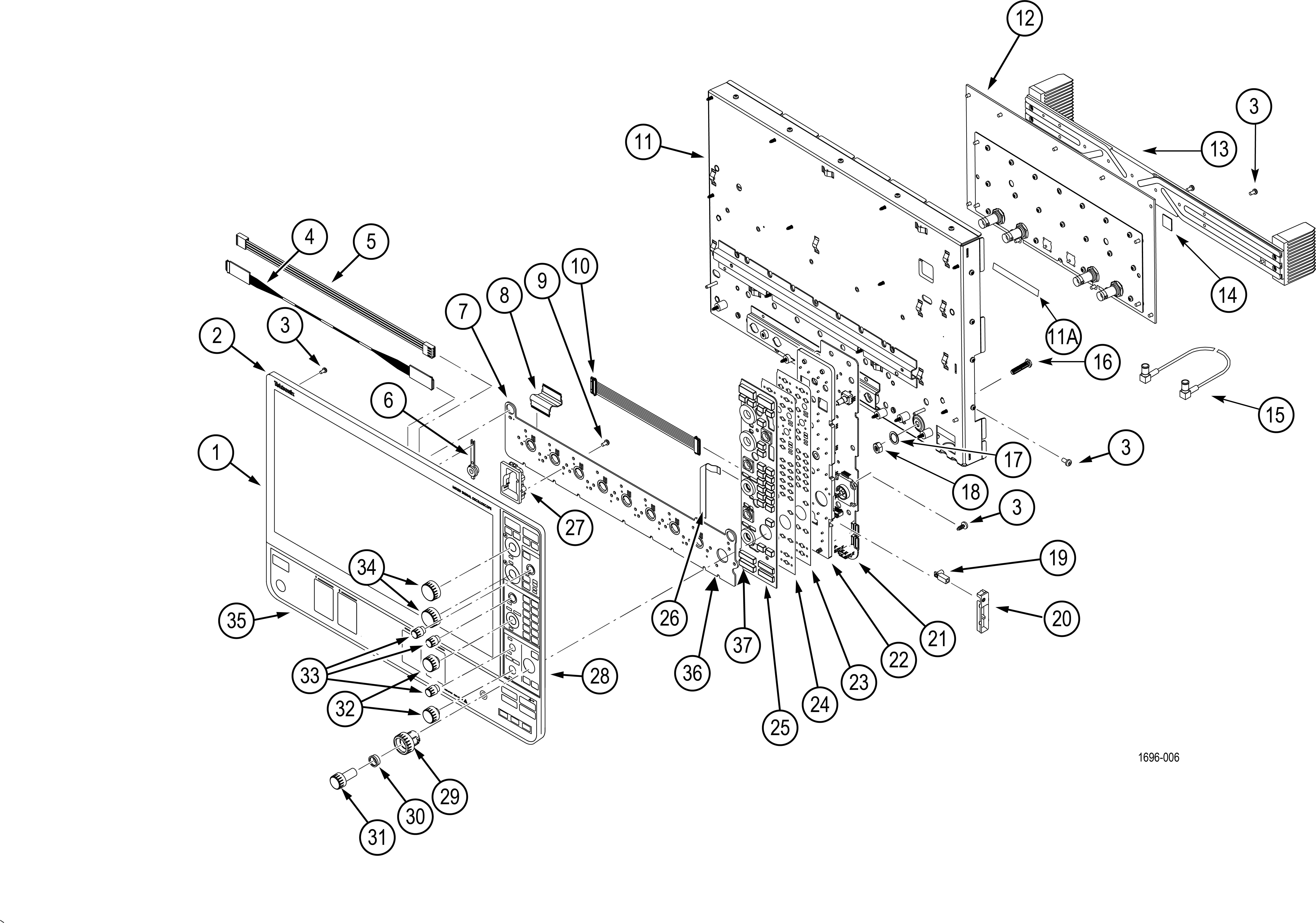
| Note:None of the components listed are user-replaceable except for front panel knobs and the front panel label. Return the instrument to your nearest Tektronix Service Center to repair or replace any internal components or assemblies in this diagram. |
| Index number | Tektronix part number | Serial no. effective | Serial no. discont'd | Qty | Name & description |
|---|---|---|---|---|---|
| Figure 1 | |||||
| -1 | 065-1073-XX | 1 | MODULE ASSY;SERVICE REPLACEMENT;1198992XX DISPLAY W/ MECHANICALS, MSO6XB Return the instrument to Tektronix for service. | ||
| -2 | 202-0582-XX | 1 | CASE, FRONT Return the instrument to Tektronix for service. | ||
| -3 | 211-1584-XX | 55 | SCREW, MACHINE, M3 X 0.5 X 6MM PAN HEAD, TORX T10 | ||
| -4 | 174-6610-XX | 1 | CABLE ASSY, DISPLAY-FRONT PANEL Return the instrument to Tektronix for service. | ||
| -5 | 174-7244-XX | 1 | CABLE, TOUCH SCREEN TO FRONT PANEL Return the instrument to Tektronix for service. | ||
| -6 | 366-0920-XX | 1 | BUTTON, POWER SWITCH, SAFETY CONTROLLED Return the instrument to Tektronix for service. | ||
| -7 | 878-1717-XX | 1 | CIRCUIT BOARD ASSY;PROBE INTERFACE, 3895488XX Return the instrument to Tektronix for service. | ||
| -8 | 174-7380-XX | 4 | CABLE, FLAT FLEX, SHIELD W/GND 0.5MM PITCH Return the instrument to Tektronix for service. | ||
| -9 | 211-1585-XX | 39 | SCREW, 3 X 0.5 X 8.0 THREAD FORMING PAN HEAD, TORX T10 | ||
| -10 | 174-6879-XX | 1 | CABLE, PICO-LOCK, 10 PIN Return the instrument to Tektronix for service. | ||
| -11 | 441-2926-00 | 1 | CHASSIS, FRONT Return the instrument to Tektronix for service. | ||
| -11A | 348-2297-XX | 1 | GASKET, CONDUCTIVE, FOF W/PSA 1MM X 7MM X 290MM | ||
| -12 | 878-1707-XX | 1 | CIRCUIT BRD ASSY;4CH AFE, 3895477XX, BOMBLD B Return the instrument to Tektronix for service. MSO64B | ||
| 878-1390-XX | 1 | CIRCUIT BRD ASSY;6CH AFE, 3895477XX, BOMBLD A Return the instrument to Tektronix for service. MSO66B | |||
| 878-1389-XX | 1 | CIRCUIT BRD ASSY;8CH AFE, 3895477XX, BOMBLD STD Return the instrument to Tektronix for service. MSO68B | |||
| -13 | 214-5508-XX | 1 | HEATSINK, AFE Return the instrument to Tektronix for service. | ||
| -14 | 342-1289-XX | 4 | THERMAL INTERFACE MATERIAL Return the instrument to Tektronix for service. If Thermal Interface Material is removed during service replace it during reassembly. MSO64B | ||
| 6 | THERMAL INTERFACE MATERIAL Return the instrument to Tektronix for service. If Thermal Interface Material is removed during service replace it during reassembly. MSO66B | ||||
| 8 | THERMAL INTERFACE MATERIAL Return the instrument to Tektronix for service. If Thermal Interface Material is removed during service replace it during reassembly. MSO68B | ||||
| -15 | 174-7121-xx | 1 | CABLE ASSEMBLY, RF, 210MM RA MCX TO RA MCX | ||
| -16 | 133-0111-xx | 1 | CONN,RF; ADAPTER,SMA JACK-MCX JACK,BULKHEAD | ||
| -17 | 210-1705-xx | 1 | LOCK WASHER 6.5MM ID X12.14MM OD | ||
| -18 | 220-0343-xx | 1 | NUT, HEX, PLAIN 1/4-36 UNS-2B X 10MMX5.56MM THICK | ||
| -19 | 131-9410-XX | 1 | CONNECTOR, RECEPTACLE, GROUND JACK Return the instrument to Tektronix for service. | ||
| -20 | 380-1277-XX | 1 | HOUSING, PROBE COMP Return the instrument to Tektronix for service. | ||
| -21 | 878-1145-XX | 1 | CIRCUIT BOARD SUBASSY; FRONT PANEL ENCODER BOARD, UNTESTED, 389493700 Return the instrument to Tektronix for service. | ||
| -22 | 361-1873-XX | 1 | SPACER, FRONT PANEL, SAFETY CONTROLLED Return the instrument to Tektronix for service. | ||
| -23 and -24 | 065-1072-XX | 1 | MODULE ASSY;SERVICE REPLACEMENT KIT;FRONT PANEL LED 8781719XX AND 2590245XX, MSO6XB Return the instrument to Tektronix for service. | ||
| -25 | 260-3144-XX | 1 | SWITCH, KEYPAD, ELASTOMERIC Return the instrument to Tektronix for service. | ||
| -26 | 174-6880-XX | 1 | CABLE, FFC, FRONT-PANEL TO PIB Return the instrument to Tektronix for service. | ||
| -27 | 351-1150-XX | 4 | GUIDE, PROBE VPI PLUS Return the instrument to Tektronix for service. MSO64B | ||
| 6 | GUIDE, PROBE VPI PLUS Return the instrument to Tektronix for service. MSO66B | ||||
| 8 | GUIDE, PROBE VPI PLUS Return the instrument to Tektronix for service. MSO68B | ||||
| -28 | 335-3680-XX | 1 | MARKER IDENTIFICATION, LABEL FRONT PANEL, MSO, 4 CHANNEL, SAFETY CONTROLLED MSO64B | ||
| 335-3678-XX | 1 | MARKER IDENTIFICATION, LABEL FRONT PANEL, MSO, 6 CHANNEL, SAFETY CONTROLLED MSO66B | |||
| 335-3676-XX | 1 | MARKER IDENTIFICATION, LABEL FRONT PANEL, MSO, 8 CHANNEL, SAFETY CONTROLLED MSO68B | |||
| -29 | 366-0946-XX | 1 | ASSEMBLY, KNOB, PAN WITH OVERMOLD | ||
| -30 | 358-0890-XX | 1 | BUSHING, SPACER, RING JOG-SHUTTLE | ||
| -31 | 366-0947-XX | 1 | ASSEMBLY, KNOB, ZOOM WITH OVERMOLD | ||
| -32 | 366-0944-XX | 2 | ASSEMBLY, KNOB, MEDIUM WITH OVERMOLD | ||
| -33 | 366-0943-XX | 3 | ASSEMBLY, KNOB, SMALL WITH OVERMOLD | ||
| -34 | 366-0945-XX | 2 | ASSEMBLY, KNOB, LARGE WITH OVERMOLD | ||
| -35 | 335-4278-XX | 1 | MARKER IDENTIFICATION, LABEL 4 CHANNEL MSO64B | ||
| 335-4255-XX | 1 | MARKER IDENTIFICATION, LABEL 6 CHANNEL MSO66B | |||
| 335-4287-XX | 1 | MARKER IDENTIFICATION, LABEL 8 CHANNEL MSO68B | |||
| -36 | 335-4073-XX | 1 | LABEL, BLACKOUT, EMAT OVERLAY | ||
| -37 | 361-1888-XX | 1 | SPACER, ENCODER/KNOB, GAP | ||
Help us improve our technical documentation. Provide feedback on our TekTalk documentation forum.