1. Introduction
1.1 Evolution of mobile communication: Early Stages, 1G to 3G
Electromagnetic waves were first discovered as a communication medium at the end of the 19th century. The first systems offering mobile telephone service (car phone) were introduced in the late 1940s in the USA and in the early 1950s in Europe. Those early “Single Cell Systems” were severely constrained by restricted mobility, low capacity, limited service and poor speech quality. The equipment was heavy, bulky, expensive and susceptible to interference. Because of those limitations, less than one million subscribers were registered worldwide by the early 1980s.
1.1.1 First Generation (1G) – Analog Cellular
The introduction of cellular systems in the late 1970s/early 1980s represented a quantum leap in mobile communication (especially in capacity and mobility). Semiconductor technology and microprocessors made smaller, lighter weight and more sophisticated mobile systems a practical reality for many more users. These First Generation cellular systems still transmit only analog voice information. The most prominent 1G systems are AMPS (Advanced Mobile Phone System), NMT (Nordic Mobile Telephone) and TACS (Total Access Communication System). With the 1G introduction, the mobile market showed annual growth rates of 30-50%, rising to nearly 20 million subscribers by 1990.
1.1.2 Second Generation (2G) – Multiple Digital Systems
The development of 2G cellular systems was driven by the need to improve transmission quality, system capacity and coverage. Further advances in semiconductor technology and microwave devices brought digital transmission to mobile communications. Speech transmission still dominates the airways, but the demands for fax, short message and data transmissions are growing rapidly. Supplementary services such as fraud prevention and encrypting of user data have become standard features that are comparable to those in fixed networks. 2G cellular systems include GSM (Global System for Mobile Communication), D-AMPS (Digital AMPS), CDMA (Code Division Multiple Access) and PDC (Personal Digital Communication).
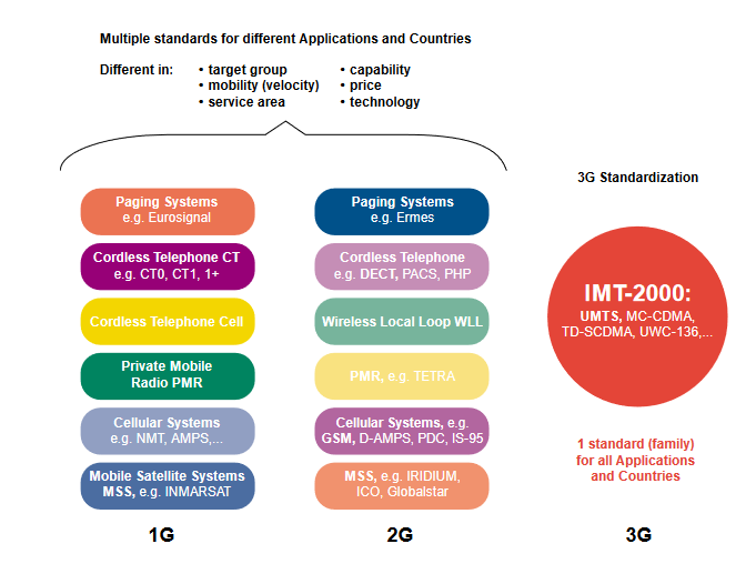
Today, multiple 1G and 2G standards are used in worldwide mobile communications. Different standards serve different applications with different levels of mobility, capability and service area (Paging Systems, Cordless Telephone, Wireless Local Loop, Private Mobile Radio, Cellular Systems and Mobile Satellite Systems). Many standards are used only in one country or region, and most are incompatible. GSM is the most successful family of cellular standards (GSM900, GSM-R, GSM1800 and GSM1900 and GSM400), supporting some 250 million of the world’s 450 million cellular subscribers with International Roaming in approximately 140 countries and 400 networks.
1.1.3 2G to 3G: GSM Evolution
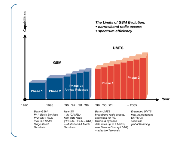
Phase 1 of the standardization of GSM900 was completed by ETSI in 1990 and included all necessary definitions for GSM network operations. Several Tele- and Bearer-Services have been defined (including data transmission up to 9.6 kbit/s), but only some very basic supplementary services were offered. As a result, GSM standards were enhanced in Phase 2 (1995) to incorporate a large variety of supplementary services that were comparable to digital fixed network ISDN standards. In 1996 ETSI decided to further enhance GSM in annual Phase 2+ releases that incorporate 3G capabilities.
GSM Phase 2+ releases have introduced important 3G features such as Intelligent Network services with CAMEL, enhanced speech codecs EFR and AMR, high data rate services and new transmission principles with HSCSD, GPRS and EDGE. UMTS is a 3G GSM successor standard that is downward compatible with GSM, using the GSM Phase 2+ enhanced Core Network.
1.2 Third Generation (3G): IMT-2000
The main characteristics of 3G systems, known collectively as IMT-2000,are a single family of compatible standards that are:
- used world-wide
- used for all mobile applications
- support both packet and circuit switched data transmission (PS & CS)
- offer high data rates up to 2 Mbit/s (depending on mobility/velocity)
- offer high spectrum efficiency
IMT-2000 is a set of requirements defined by the ITU. IMT stands for International Mobile Telecommunication, “2000” represents both the scheduled year for initial trial systems and the frequency range of 2000 MHz (WARC’92: 1885 - 2025 MHz & 2110 - 2200 MHz). All 3G standards have been developed by “regional” Standard Development Organizations (SDO). In total, proposals for 17 different IMT-2000 standards were submitted by regional SDOs to ITU in 1998 - 11 proposals for terrestrial systems and 6 for Mobile Satellite Systems (MSS). Evaluation of the proposals was completed at the end of 1998, and negotiations to build consensus among differing views were completed in mid 1999. All 17 proposals have been accepted by ITU as IMT-2000 standards. The specification for the Radio Transmission Technology (RTT) was released at the end of 1999.
The most important IMT-2000 proposals are the UMTS (W-CDMA) as the successor to GSM, cdma2000 as the IS-95 successor and TD-SCDMA (UWC-136/EDGE) as TDMA-based enhancements to D-AMPS/GSM – all of which are leading previous standards toward the ultimate goal of IMT 2000.
UMTS (Universal Mobile Telecommunication System), also referred to as W-CDMA, is one of the most significant advances in the evolution of telecommunications into 3rd Generation Mobile Networks. UMTS allows many more applications to be introduced to a worldwide base of users and provides a vital link between today’s multiple GSM systems and the ultimate single worldwide standard for all mobile telecommunications (IMT-2000). The new network also addresses the growing demand of mobile and Internet applications for new capacity in the overcrowded mobile communications sky. UMTS increases transmission speed to 2 Mbits/s per mobile user and establishes a global roaming standard.
UMTS is being developed by 3GPP (Third Generation Partnership Project), a joint venture of several Standards Development Organizations - ETSI (Europe), ARIB/TTC (Japan), ANSI T1 (USA), TTA (South Korea) and CWTS (China). To reach global acceptance, 3GPP is introducing UMTS in Phases and Annual Releases. The first release (UMTS Rel. ‘99), introduced in December of 1999, defines enhancements and transitions for existing GSM networks. For the second Phase (UMTS Rel. ´00), similar transitions are being proposed as enhancements for IS95 (with cdma2000) and TDMA (with TD-CDMA and EDGE)
The most significant change in Rel. ‘99 is the new UMTS Terrestrial Radio Access (UTRA), a W-CDMA radio interface for land based communications. UTRA supports Time Division Duplex (TDD) and Frequency Division Duplex (FDD). The TDD mode is optimized for public Micro & Pico cells and unlicensed cordless applications. The FDD mode is optimized for wide area coverage; i.e. public Macro & Micro cells. Both modes offer flexible and dynamic data rates up to 2 Mbit/s. Another newly defined UTRA mode – Multi Carrier (MC) – is expected to establish compatibility between UMTS and cdma2000.
2 UMTS network architecture
2.1 Principles
UMTS (Rel. '99) incorporates enhanced GSM Phase 2+ Core Networks with GPRS (General Packet Radio Services) and CAMEL (Customized Applications for Mobile network Enhanced Logic). This enables network operators to enjoy the improved cost efficiency of UMTS while protecting their 2G investments and reducing the risks of implementation.
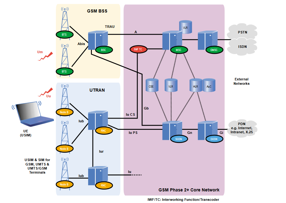
In UMTS release 1 (Rel. '99), a new radio access network UTRAN (UMTS Terrestrial Radio Access Network) is introduced. UTRAN, the UMTS RAN, is connected via the Iu-Interface (Iu-PS for PS data / Iu-CS for CS data) to the GSM Phase 2+ CN.
"GSM-only" Mobile Stations (MS) will be connected to the network via the Um GSM radio interface. UMTS/GSM Dual-Mode User Equipment (UE) will be connected to the network via UMTS radio interface Uu at very high data rates (up to almost 2 Mbit/s). Outside the UMTS service area, UMTS/GSM UE will be connected to the network at reduced data rates via the Um GSM air interface.
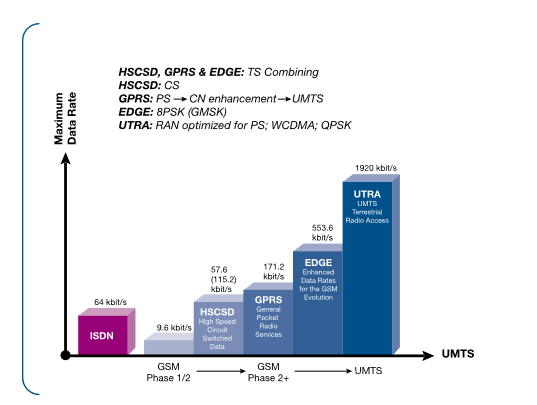
Maximum data rates are 115 kbit/s for CS data by HSCSD (High Speed Circuit Switched Data), 171 kbit/s for PS data by GPRS and 553 kbit/s by EDGE (Enhanced Data Rates for the GSM Evolution). Handover between UMTS and GSM is supported, and handover between UMTS and other 3G systems (e.g. MC-CDMA) will be supported in order to achieve true worldwide access.
2.2 The UMTS Network Architecture
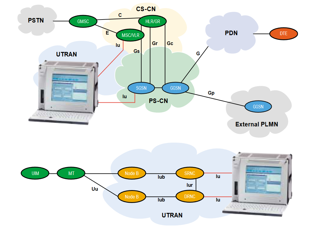
The Public Land Mobile Network (PLMN) described in UMTS Rel. ´99 incorporates three major categories of network elements:
- GSM Phase 1/2 core network elements: MSC,VLR, HLR, AC and EIR
- GSM Phase 2+ enhancements: GPRS (SGSN and GGSN) and CAMEL (CSE)
- UMTS specific modifications and enhancements, particularly the UMTS Terrestial Radio Access Network (UTRAN)
2.2.1 Network Elements from GSM Phase 1/2
The GSM Phase 1/2 PLMN consists of three subsystems: the Base Station Subsystem (BSS), the Network Switching Subsystem (NSS) and the Operation Subsystem (OSS). The BSSconsists of the functional units: Base Station Controller (BSC), Base Transceiver Station (BTS) and Transcoding & RateAdaptation Unit (TRAU). TheNSS consists of the functional units: Mobile Services switching Center (MSC), Visitor Location Register (VLR), Home Location Register (HLR), Equipment Identity Register (EIR) and the Authentication Center (AC). The MSC provides functions such as switching, signaling, Paging, and Inter-MSC Handover. TheOSS consists of Operation & Maintenance Centers (OMC), which are used for remote and centralized Operation, Administration and Maintenance tasks.
2.2.2 Network Elements from GSM Phase 2+GPRS (General Packet Radio Services)
The most important evolutionary step of GSM towards UMTS is GPRS. GPRS introduces Packet Switching (PS) into the GSM Core Network and allows direct access to Packet Data Networks (PDN). This enables high data rate PS transmission well beyond the 64 kbit/s limit of ISDN through the GSM CN, a necessity for UMTS data transmission rates of up to 2 Mbit/s. GPRS prepares and optimizes the CN for high data rate PS transmission, as does UMTS with UTRAN over the RAN. Thus, GPRS is a prerequisite for the UMTS introduction.
Two functional units extend the GSM NSS architecture for GPRS PS services: the Gateway GPRS Support Node (GGSN) and the Serving GPRS Support Node (SGSN).
The GGSN has functions comparable to a GMSC. The SGSN resides at the same hierarchical level as a VMSC/VLR and therefore performs comparable functions such as routing and mobility management.
CAMEL (Customized Applications for Mobile network Enhanced Logic)
CAMEL enables worldwide access to operator specific Intelligent Network (IN) applications such as Prepaid, Call Screening, and Supervision. CAMEL is the primary GSM Phase 2+ enhancement for the introduction of the UMTS Virtual Home Environment (VHE) concept. VHE is a platform for flexible service definition (collection of Service Creation Tools) that enables the operator to modify or enhance existing services and/or to define new services. Furthermore, VHE enables worldwide access to these operator-specific services in every GSM and UMTS PLMN and introduces Location Based Services (by interaction with GSM/UMTS Mobility Management).
A CAMEL Service Environment (CSE) and a new CCS7 protocol, the CAMEL Application Part (CAP) are required on the CN to introduce CAMEL.
2.2.3 Network Elements from UMTS Phase 1
As mentioned above, UMTS differs from GSM Phase 2+ mostly in the new principles for air interface transmission (W-CDMA instead of TDMA/FDMA). Therefore, a new radio access network called UTRAN must be introduced with UMTS. Only minor modifications, such as allocation of the transcoding function (TC) for speech compression to the CN, are needed in the Core Network to accommodate the change. The TC function is used together with an Interworking Function (IWF) for protocol conversion between the A and the Iu-CS interfaces.
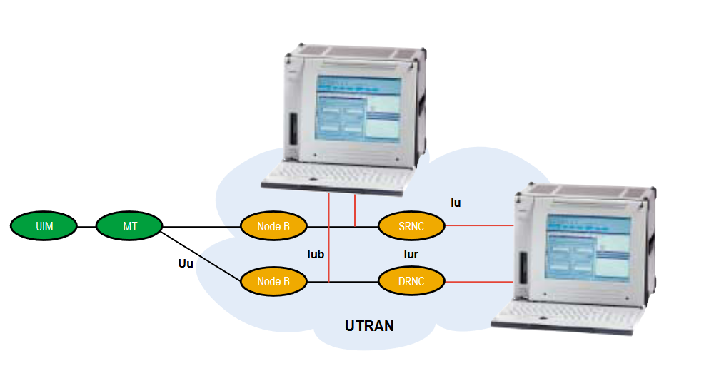
UTRAN (UMTS Terrestrial Radio Access Network)
The UMTS standard can be seen as an extension of existing networks. Two new network elements are introduced in UTRAN, Radio Network Controller (RNC) and Node B. UTRAN is subdivided into individual Radio Network Systems (RNS), where each RNS is controlled by a Radio Network Controller (RNC). The RNC is connected to a set of Node B elements, each of which can serve one or several cells.
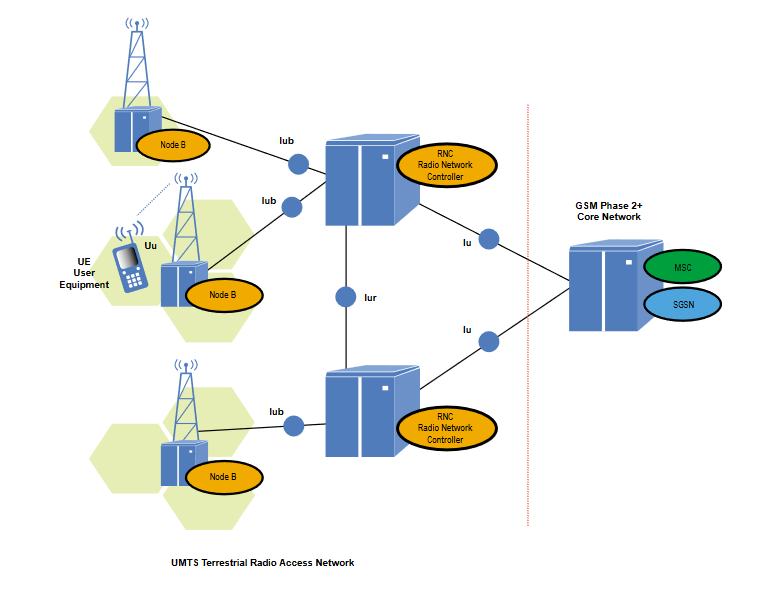
Existing network elements, such as MSC, SGSN and HLR, can be extended to adopt the UMTS requirements, but RNC, Node B and the handsets must be completely new designs. RNC will become the replacement for BSC, and Node B fulfills nearly the same functionality as BTS. GSM and GPRS networks will be extended and new services will be integrated into an overall network that contains both existing interfaces such as A, Gb, Abis and new interfaces that include Iu, Iub and Iur
UMTS defines four new open interfaces:
- Uu: User Equipment (UE) to Node B (UTRA, the UMTS WCDMA air interface)
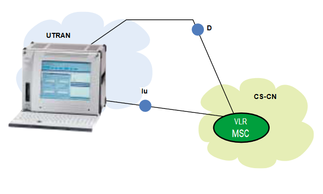
- Iu: RNC to GSM Phase 2+ Core Network interface (MSC/VLR or SGSN)
- Iu-CS for circuit switched data
- Iu-PS for packet switched data
- Iub: RNC to Node B interface
- Iur: RNC to RNC interface; not comparable to any interface in GSM
The Iu, Iub and Iur interfaces are based on ATM transmission principles.
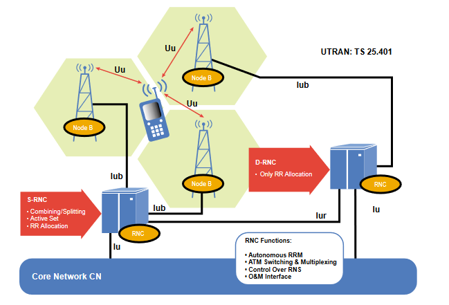
The Radio Network Controller (RNC) enables autonomous Radio Resource Management by UTRAN. It performs the same functions as the GSM Base Station Controller (BSC), providing central control for the Radio Network System (RNS) elements (RNC and Node Bs)
The RNC handles protocol exchanges between Iu, Iur, and Iub interfaces and is responsible for centralized Operation & Maintenance of the entire RNS with access to the Operation SubSystem (OSS). Because the interfaces are ATM-based, the RNC switches ATM cells between them. The user’s circuit-switched and packet switched data coming from Iu-CS and Iu-PS interfaces are multiplexed together for multimedia transmission via Iur, Iub, and Uu interfaces to and from the User Equipment (UE)
The RNC uses the Iur interface, which has no equivalent in GSM BSS, to autonomously handle 100% of the Radio Resource Management (RRM), eliminating that burden from the Core Network. Serving control functions such as Admission, RRC connection to the UE, Congestion and Handover/Macro Diversity are managed entirely by a single Serving RNC (SRNC)
If another RNC is involved in the active connection through an Inter-RNC Soft Handover, it is declared a Drift RNC (DRNC). The DRNC is only responsible for the allocation of Code resources. A reallocation of the SRNC functionality to the former DRNC is possible (SRNS Relocation). The term Controlling RNC (CRNC) is used to define the RNC that controls the logical resources of its UTRAN access points.
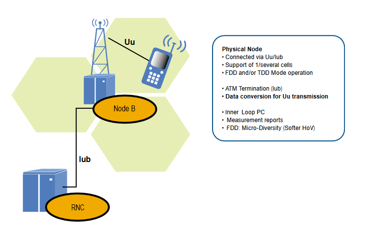
Node B is the physical unit for radio transmission/reception with cells. Depending on sectoring (Omni-/Sector Cells) one or more cells may be served by a Node B. A single Node B can support both FDD and TDD modes, and it can be co-located with a GSM BTS to reduce implementation costs. Node B connects with the UE via the W-CDMA Uu radio interface and with the RNC via the Iub ATM-based interface. Node B is the ATM termination point
The main task of Node B is the conversion of data to/from the Uu radio interface, including Forward Error Correction FEC, Rate Adaptation, W-CDMA Spreading/De-Spreading, and QPSK Modulation on the air interface. It measures quality and strength of the connection and determines the Frame Error Rate (FER), transmitting these data to the RNC as a Measurement Report for Handover and Macro Diversity
Combining. The Node B is also responsible for the FDD Soft Handover. This Micro Diversity combining is carried out independently, eliminating the need for additional transmission capacity in the Iub.
The Node B also participates in Power Control, as it enables the UE to adjust its power using DL TPC commands via the Inner Loop Power Control on the basis of UL Transmit Power Control TPC information. The predefined values for Inner Loop Power Control are derived from the RNC via Outer Loop Power Control.
The UMTS UE is based on the same principles as the GSM MS – the separation between ME and the UMTS SIM card (USIM). The following figure shows the user equipment functions.
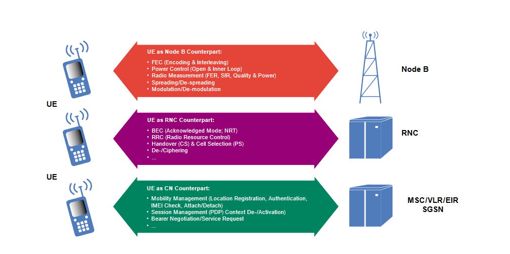
The UE is the counterpart to the various network elements in many functions and procedures.
3 UMTS Interfaces
Many new protocols have been developed for the four new interfaces specified in UMTS: Uu, Iub, Iur, and Iu. This primer is organized by the protocols and shows their usage in the interfaces. That means protocols will be described individually. Only the references to the interfaces are indicated. Interface specific explanations of the protocols are however not included. Before we review the individual interface protocols, we introduce the UMTS general protocol model.
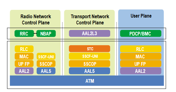
3.1 General Protocol Model [3G TS 25.401]
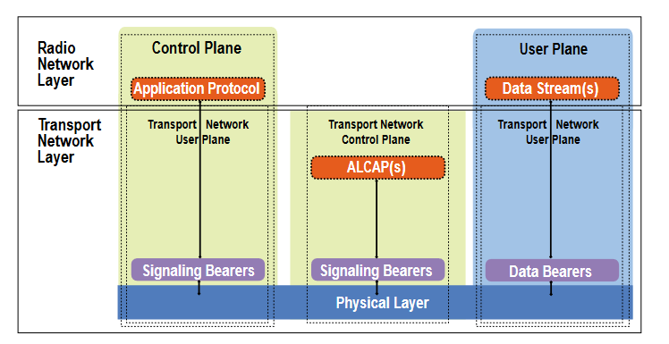
UTRAN interface consists of a set of horizontal and vertical layers (see figure 9). The UTRAN requirements are addressed in the horizontal Radio Network Layer across different types of control and user planes. Control planes are used to control a link or a connection; user planes are used to transparently transmit user data from the higher layers. Standard transmission issues, which are independent of UTRAN requirements, are applied in the horizontal Transport Network Layer.
Five major protocol blocks are shown in figure 9:
- Signaling Bearers are used to transmit higher layers’ signaling and control information. They are set up by O&M activities.
- Data Bearers are the frame protocols used to transport user data (data streams). The Transport Network Control Plane (ALCAP) sets them up.
- Application Protocols are used to provide UMTS specific signaling and control within UTRAN, such as to set up bearers in the Radio Network Layer.
- Data Streamscontain the user data that are transparently transmitted between the network elements. User data comprises the subscriber’s personal data and mobility management information that are exchanged between the peer entities MSC and UE.
- ALCAP (Access Link Control Application Part) protocol layers are provided in the Transport Network Control Plane. They react to the Radio Network Layer’s demands to set up, maintain, and release data bearers. The primary objective of introducing the Transport Network Control Plane was to totally separate the selection of the Data Bearer technology from the Control Plane (where the UTRAN specific Application Protocols are located). The Transport Network Control Plane is present in the Iu-CS, Iur, and Iub interfaces. In the remaining interfaces where there is no ALCAP signaling, preconfigured Data Bearers are activated.
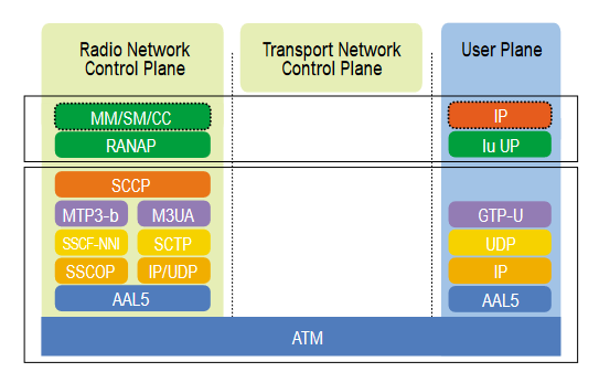
3.2 Application Protocols
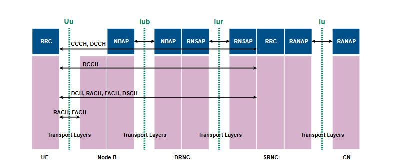
Application Protocols are layer 3 protocols that are defined to perform UTRAN specific signaling and control. A complete UTRAN and UE control plane protocol architecture is illustrated in figure 11. UTRAN specific control protocols exist in each of the four interfaces.
Iu: Radio Access Network Application Part (RANAP) [3G TS 25.413]
This protocol layer provides UTRAN specific signaling and control over the Iu-interface. The following is a subset of the RANAP functions:
- Overall Radio Access Bearer (RAB) Management, which includes the RABs’ setup, maintenance, and release
- Management of Iu connections
- Transport of Non-Access Stratum (NAS) information between the UE and the CN. For example, NAS contains the mobility management signaling and broadcast information.
- Exchanging UE location information between the RNC and CN
- Paging requests from the CN to the UE
- Overload and general error situation handling
Iur: Radio Network Sublayer Application Part (RNSAP) [3G TS 25.423]UTRAN specific signaling and control over this interface contains:
- management of radio links, physical links and common transport channel resources
- paging
- affecting an SRNC relocation
- measurements of dedicated resources
Iub: Node B Application Part (NBAP) [3G TS 25.433] UTRAN specific signaling and control in the Iub-interface includes:
- management of common channels, common resources, and radio links
- configuration management, such as cell configuration management
- measurement handling and control
- synchronization (TDD)
- reporting of error situations
Uu: Radio Resource Control (RRC) [3G TS 25.331]
This layer handles the control plane signaling over the Uu interface between the UE and the UTRAN (see also figure 15). Some of the functions offered by the RRC are:1
- Broadcasting information
- Management of connections between the UE and the UTRAN, which include their establishment, maintenance, and release.
- Management of the Radio Bearers, which include their establishment, maintenance, release, and the corresponding connection mobility
1 The RRCs also perform local inter-layer control services, which are not discussed in this document
- Ciphering control
- Outer loop power control
- Message integrity protection
- Timing advance in the TDD mode
- UE measurement report evaluation
- Paging and notifying
Two modes of operation are defined for the UE – the idle mode and the dedicated mode. In the idle mode the peer entity of the UE’s RRC is at the Node B, while in the dedicated mode it is at the SRNC. The dedicated mode is shown in figure 11.
Higher-layer protocols to perform signaling and control tasks are found on top of the RRC. The MM and CC are defined in the existing GSM specifications. Even though MM and CC occur between the UE and the CN and are therefore not part of UTRAN specific signaling (see figure UU), they demand basic support from the transfer service which is offered by Duplication Avoidance (see 3G TS 23.110). This layer is responsible for in-sequence transfer and priority handling of messages. It belongs to UTRAN, even though its peer entities are located in the UE and CN.
3.3 Transport Network Layer specific layer 3 signaling and control protocols.
Two types of layer 3 signaling protocols are found in the Transport Network Layer:
- Iu, Iur: Signaling Connection Control Part (SCCP) [ITU-T Q.711 - Q.716] provides connectionless and connection-oriented services. On a connection-oriented link it separates each mobile unit and is responsible for the establishment of a connection-oriented link for each and every one of them.
- Iu-CS, Iur, Iub: Access Link Control Application Part (ALCAP) [ITU-T Q.2630.1, Q.2150.1, and Q.2150.2]. Layer 3 signaling is needed to set up the bearers to transmit data via the User Plane. This function is the responsibility of the ALCAP, which is applied to dynamically establish, maintain, release, and control AAL2 connections. ALCAP also has the ability to link the connection control to another higher layer control protocol. This, and additional capabilities were specified in ITU-T Q.2630.1. Because of the protocol layer specified in Q.2630.1, a converter is needed to correspond with underlying sub-layers of the protocol stack. These converters are called (generically) Signaling Transport Converter (STC). Two converters are defined and applied in UTRAN:
- Iu-CS, Iur: AAL2 STC on Broadband MTP (MTP3b) [Q.2150.1]
- Iub: AAL2 STC on SSCOP [Q.2150.2]
3.4 Transport Network Layer specific “transmission” technologies.
Now that we have a circuit switched and packet switched domain in the CN and a growing market for packet switched network solutions, a new radio access network must be open to both types of traffic in the long run. That network must also transmit the layer 3 signaling and control information. ATM was selected as the layer 2 technology, but higher layer protocols used in the Transport Network Layer demonstrate the UMTS openness to a pure IP solution.
Iu, Iur, Iub: Asynchronous Transfer Mode (ATM) [ITU-T I.3610] Broadband communication will play an important role with UMTS. Not only voice, but also multimedia applications such as video conferencing, exploring the Internet and document sharing are anticipated. We need a data link technology that can handle both circuit-switched and packetswitched traffic as well as isochronous and asynchronous traffic. In UMTS (Release ‘99), ATM was selected to perform this task.
An ATM network is composed of ATM nodes and links. The user data is organized and transmitted in each link with a stream of ATM cells. ATM Adaptation Layers (AAL) are defined to enable different types of services with corresponding traffic behavior. Two of these are applied in UTRAN:
- Iu-CS, Iur, Iub: ATM Adaptation Layer 2 (AAL2) [ITU-T I.363.2] With AAL2, isochronous connections with variable bit rate and minimal delay in a connection-oriented mode are supported. This layer was designed to provide real time service with variable data rates, such as voice and video.
- Iu-PS, Iur, Iub: ATM Adaptation Layer 5 (AAL5) [ITU-T I.363.5] With AAL5, isochronous connection with CBR, VBR, UBR, and ABR in a connection-oriented mode are supported. This layer is used for IP and signaling. In UTRAN, AAL5 is used to carry the packet switched user traffic in the Iu-PS-interface and the signaling and control data throughout.
In order to carry signaling and control data, the AAL5 has to be “enhanced.” Here, UTRAN offers both a “classical” ATM solution and an IP-based approach:
- Signaling AAL and MTP3b
To make Signaling AAL (SAAL) available in place of the AAL5 sublayer SSCS, the SSCOP, which provides a reliable data transfer service, and the SSCF, which acts as coordination unit, are defined: - Iu, Iur, Iub: Service Specific Connection Orientated Protocol (SSCOP) [ITU-T Q.2110]
The SSCOP is located on top of the AAL layer. It is a common connection-oriented protocol which provides a reliable data transfer between peer entities. Its capabilities include the transfer of higher layer data with sequence integrity, flow control, connection maintenance in case of a longer data transfer break, error correction by protocol control information, error correction by retransmission, error reporting to layer management, status report, and more.
Two versions of the Service Specific Coordination Function (SSCF) are defined: one for signaling at the User-to-Network Interface (UNI), and one for signaling at the Network-Node Interface (NNI):
- Iub: Service Specific Coordination Function for Support of Signaling at the User-Network Interface (SSCF-UNI) [ITU-TQ.2130]
The SSCF-UNI receives layer 3 signaling and maps it to the SSCOP, and visa versa. The SSCF-UNI performs coordination between the higher and lower layers. Within UTRAN, it is applied in Iub with the NBAP and ALCAP on top of the SSCF-UNI. - Iu, Iur: Service Specific Coordination Function at the Network Node Interface (SSCF-NNI) [ITU-T Q.2140]
The SSCF-NNI receives the SS7 signaling of a layer 3 and maps it to the SSCOP, and visa versa. The SSCF-NNI performs coordination between the higher and the lower layers. Within UTRAN, MTP3b has the higher layer 3, which requires service from the SSCOP-NNI.
Originally the SS7 protocol layer, SCCP relies on the services offered by MTP, so the layer 3 part of the MTP must face the SCCP layer:
- Iu, Iur: Message Transfer Part Level 3 (MTP3b) [ITU-T Q.2210]
Signaling links must be controlled in level 3 for: message routing, discrimination and distribution (for point-to-point link only), signaling link management, load sharing, etc. The specific functions and messages for these are defined by the MTP3b, which requires the SSCF-NNI to provide its service.
The layer 3 signaling and control data can also be handled by an enhanced IP-protocol stack using a tunneling function (see figure 12).Tunneling is also applied for packet switched user data over the Iu-PSinterface (see figure 14).
- IP over ATM:
- lu-PS, Iur: Internet Protocol (IP) [IETF RFC 791, 2460, 1483, 2225], User Datagram Protocol (UDP) [IETF RFC 768] TheInternet Protocol can be encapsulated and then transmitted via an ATM connection, a process which is described in the RFC 1483 and RFC 2225. Both IPv4 and IPv6 are supported. IP is actually a layer 3 protocol. UDP is applied on top of the unreliable layer 4 protocol. The objective is to open this signaling link to future “pure IP” network solutions
In order to tunnel SCCP or ALCAP signaling information, two protocols are applied:
- Iu-PS, Iur: Simple Control Transmission Protocol (SCTP) [IETF draft-ieft-sigtran-sctp-v0.txt]
This protocol layer allows the transmission of signaling protocols over IP networks. Its tasks are comparable with MTP3b. On Iu-CS, SS7 signaling must be tunneled between the CN and the RNC. This is planned to be done with the Iu-PS, Iur: SS7 MTP3-User Adaptation Layer (M3UA) [IETF draft-ietf-sigtran-m3ua-02.txt]
The tunneling of packet switched user data is done with the:
- Iu-PS: GPRS Tunneling Protocol (GTP) [3G TS 29.060]
The GTP provides signaling (GTP-C) and data transfer (GTP-U) procedures. Only the latter is applied in the Iu-PS interface, since the control function is handled by the RANAP protocol. The GTP-U is used to tunnel user data between the SGSN and the RNC.
3.5 Iu, Iur, Iub: The Physical Layers [3G TS 25.411]
The physical layer defines the access to the transmission media, the physical and electrical properties and how to activate and de-activate a connection. It offers to the higher layer physical service access points to support the transmission of a uniform bit stream. A huge set of physical layer solutions is allowed in UTRAN, including: ETSI STM-1 (155 Mbps), STM-4 (622 Mbps); SONET STS-3c (155 Mbps), STS-12c (622 Mbps); ITU STS-1 (51 Mbps), STM-0 (51 Mbps); E1 (2 Mbps), E2 (8 Mbps), E3 (34 Mbps), T1 (1.5 Mbps), T3 (45 Mbps); J1 (1.5 Mbps), J2 (6.3 Mbps).
With the above protocol layers, the interfaces Iu, Iur, and Iur are fully described. There is only the air interface left for a more detailed analysis:
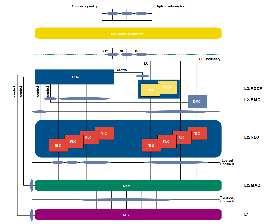
3.6 The air interface Uu [3G TS 25.301]
The air interface solution is usually a major cause for dispute when specifying a new radio access network. Figure Uu shows the realization of the lower parts of the protocol stack in the UE. As can be seen, a physical layer, data link layer, and network layer (the part for the radio resource control (RRC)) have been specified.
The physical layer is responsible for the transmission of data over the air interface. The FDD and TDD W-CDMA solutions have been specified in UMTS Rel. ‘99.
The data link layer contains four sub-layers:
- Medium Access Control (MAC) [3G TS 25.321]
The MAC layer is located on top of the physical layer. Logical channels are used for communication with the higher layers. A set of logical channels is defined to transmit each specific type of information. Therefore, a logical channel determines the kind of information it uses.
The exchange of information with the physical layer is realized with transport channels. They describe how data is to be transmitted over the air interface and with what characteristics.
The MAC layer is responsible for more than mapping the logical channels into the physical ones. It is also used for priority handling of UEs and the data flows of a UE, traffic monitoring, ciphering, multiplexing, and more. - Radio Link Control (RLC) [3G TS 25.322] is responsible for acknowledged or unacknowledged data transfer, establishment of RLC connections, transparent data transfer, QoS settings,unrecoverable error notification, ciphering, etc. There is one RLC connection per Radio Bearer
The two remaining layer 2 protocols are used only in the user plane:
- Packet Data Convergence Protocol (PDCP) [3G TS 25.323] is responsible for the transmission and reception of Radio Network Layer PDUs. Within UMTS several different network layer protocols are supported to transparently transmit protocols. At the moment IPv4 and IPv6 are supported, but UMTS must be open to other protocols without forcing the modification of UTRAN protocols. This transparent transmission is one task of PDCP; another is to increase channel efficiency (by protocol header compression, for example).
- Broadcast/Multicast Control (BMC) [3G TS 25.324] offers broadcast/multicast services in the user plane. For instance, it stores SMS CB messages and transmits them to the UE.
4 UMTS and UTRAN Measurement Objectives
As noted in the preceding section, four new interfaces have been introduced with UMTS/UTRAN. With the new interfaces came a huge set of protocol layers for mobile communication networks. Dealing with these new protocols presents a demanding challenge to manufacturers, operators, and measurement equipment suppliers.
4.1 Measurement Approaches
Nearly all measurement situations can be considered in three categories with related approaches. Even though there are situations where two or more approaches could be applied to the same interface, the first steps in protocol testing should always be to determine the characteristics of the system under test and the test objectives.
- Do you have a living network that you should not, or are not,allowed to disturb?
Use the non-intrusive Monitoring approach. - Do you have a ‘dead’ node or system that needs to be externally stimulated?
Use the Simulation/Emulation approach. - Do you need to verify compatibility with standards or with other equipment?
Use the Conformance approach.
4.1.1 Monitoring [see also CCITT 880 and GSM Rec. 12.04]
Monitoring is the process of collecting data from the interface using either the K1205, a pure monitoring device, or the K1297, which can also perform simulation and emulation. The main reason for operators and manufacturers to collect data is to retrieve the necessary information for decision making in relation to a specified objective. The item under investigation can be an individual network element, parts of the PLMN or even the whole PLMN. The major objectives for monitoring data collections are:
- to get an overall view of the actual performance level
- to determine a possible need for an improvement
- to discover the differences between specified/ predicted characteristics its actual performance
- to improve predictions of behavior and potential problems.
Interface monitoring can collect data and present results in two ways:
measurement result collection: Use of cumulative counters to capture the number of occurrences of an event and/or discrete event registers to capture and trace specified results such as overload situations and failures.
data review for evaluation: The storage of measured data for subsequent review and analysis. The amount of data is normally reduced through the filtering of specified events (such as abnormal call termination), the use of statistical methods or the selection of specific conditions (tracing data at a defined address, tracing a call set-up, etc.).
4.1.2 Simulation
Simulation is the representation or imitation of a process or system by another device. In a test environment, a simulator can be used in place of a network element or a part of the network to produce desired conditions. For instance, when testing an RNC the test equipment can simulate the Core Network behavior, keeping the RNC independent of the network. Simulators are used:
- To get information about the dependability of a network element (NE). Normal and abnormal situations are specified and simulated, and the NE’s ability to cope with the simulated environment allows the operator to predict how well the NE will perform in the field. Simulations are also used for conformance testing where standardized conditions are applied to the NE.
- To substitute missing network elements or parts of a network during the development process. Simulation creates a realistic operating environment for the item under development.
- To save development and installation costs. The strong and weak points of an item can be discovered in the development process, before introducing it to an operating network.
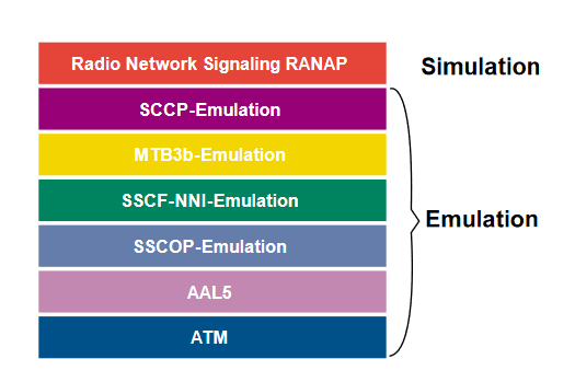
4.1.3 Emulation
Emulation is a higher form of simulation where the behaviors of selected layers of communication protocols are simulated automatically and in conformance with standards. For instance, the simulation of the Iu RANAP is based on an emulation of the corresponding lower layers. While the lower layers are defined to act as specified, the simulated layer can be used to deliberately add faults to test an element’s ability to handle them.
4.1.4 Conformance Testing [ETSI ETR 021]
Standards allow different manufacturers to develop systems that can interoperate and exchange and handle information. A system or an implementation is declared conformant when its capabilities and external behavior meet those defined in the referenced standards. Conformance testing is the verification process that determines whether a system or an implementation is conformant. While specific conformance tests are defined in UMTS for the air interface (see 3G TS 34.xxx), conformance tests of the remaining UTRAN interfaces are still dependent upon mutual agreement between manufacturers, operators, and measurement suppliers.
4.2 Test Procedures
Several different test configurations are supported in the Tektronix K1297:
1. The Simulation/Emulation of the CN and the UTRAN or RNC. Figure 17 demonstrates how the manufacturer’s development and system integration process can be supported by simulation/emulation. The device under test’s environment can be simulated under both normal and abnormal conditions, and the dependability of its response can be measured. When the K1297 is the “peer entity” to the CN, it can simulate and emulate the UTRAN (including the UE) and/or the RNC alone.
2. Active and passive monitoring are primary measurement tools. Monitoring for all UMTS interfaces will be supported. The manufacturer but and the operator can evaluate network element performance. Statistical data can be retrieved that give the operator additional information about the load and type of traffic, such as BHCA’s. A CN-simulation and Iub-interface monitoring application are shown in figure 18.
3. Conformance testing will be offered to verify an item’s conformant behavior. As standards are agreed upon, conformance test suites will be made available in software upgrades for the K1297. The conformance testing of CN elements can be seen In Figure TS3 - the K1297 simulates the HLR to guarantee that the network elements under test only get approved data.
5 Conclusion:
This second release of the UMTS Primer presents information for the test engineer who is interested in solutions for the new world of 3G mobile networks. Updates will follow in the near future, as the standards continue to evolve. This document is also available at our web site (www.tektronix.com/commtest), along with updates and related documents (including a series of Application Notes on the testing of UMTS interfaces)
Tektronix is committed to the most advanced test solutions for mobile networks. As mobile networks continue to evolve through GPRS, UMTS and cdma2000, we will keep you in the forefront with the latest testing products and methods.
We welcome your comments and suggestions for improving these documents and your ideas for developing other tools to help you meet the measurement challenges of new wireless systems.