Contact us
Call
Call us at
Available 6:00 AM – 5:00 PM (PST) Business Days
Download
Download Manuals, Datasheets, Software and more:
Feedback
100GBASE-KR4, 100GBASE-CR4, & CAUI-4 Datasheet
Compliance and Characterization Solution for Sampling Scopes

Compliance and Characterization Solution for Sampling Scopes
IEEE 802.3bj (100GBASE-KR4/100GBASE-CR4) and IEEE 802.3bm (CAUI-4) Electrical Equivalent Time Transmitter Compliance and Characterization Solution
The Tektronix Equivalent Time Instrument based 100GBASE-KR4/100GBASE-CR4 or CAUI-4 Transmitter Characterization automation system provides turnkey testing and debug of three of the 100G Ethernet industries most common electrical interfaces. As silicon designers need to perform 100GBASE-KR4 and 100GBASE-CR4 validation of their silicon, and system designers need to perform 100GBASE-CR4 and CAUI-4 validation, these three tools are brought together in a single 100G-TXE (Electrical Transmitter Validation) package.
100G-TXE application package is an automated compliance and characterization solution for IEEE 100GBASE-KR4, 100GBASE-CR4, and IEEE CAUI-4 users. This package operates on DSA8300 sampling instrument with 80E09B or 80E10B electrical acquisition modules and 82A04B Phase Reference module. The 100G-TXE loads the required Bessel Thomson roll-off filter which constrains the channel requirements to IEEE mandated 33 GHz, 3 dB point. The unique lower noise levels of the DSA8300 sampling architecture supports key signal to noise and distortion ratio (SNDR) measurement, the result of which is attained with the highest possible margin on the DSA8300 system. The 100G-TXE solution is also available on Real Time Scope (DPO70KSX and 70KDX series).
Key features
- 100G-TXE offers streamlined and fully automated transmitter characterization of 802.3bj’s 100GBASE-KR4/100GBASE-CR4 electrical transmitter specifications, as well as 802.3bm CAUI-4 specification.
-
Extends 80SJNB for analysis and debug into 100GBASE-KR4/100GBASE-CR4 and CAUI-4 1.
1CAUI-4 is also known as CAUI.
Applications
- Measurements of electrical transmitter on 25+ Gb/s PAM2 NRZ lanes
- Validation of 100GBASE-KR4/100GBASE-CR4 and CAUI-4
IEEE 802.3bj (100GBASE-KR4) Electrical Transmitter Measurements fully automated
| Parameter | Subclause reference | Value | Units |
|---|---|---|---|
| Signaling rate | 93.8.1.2 | 25.78125±100 ppm | GBd |
| Differential peak-to-peak output voltage (max) | |||
| Transmitter disabled | 93.8.1.3 | 30 | mV |
| Transmitter enabled | 93.8.1.3 | 1200 | mV |
| DC common-mode output voltage (max) | 93.8.1.3 | 1.9 | V |
| DC common-mode output voltage (min) | 93.8.1.3 | 0 | V |
| AC common-mode output voltage (RMS, max) | 93.8.1.3 | 12 | mV |
| Output waveform | |||
| steady-state voltage (max) | 93.8.1.5.2 | 0.6 | V |
| steady-state voltage (min) | 93.8.1.5.2 | 0.4 | V |
| Linear fit pulse peak (min) | 93.8.1.5.2 | 0.71 x vf | V |
| Normalized coefficient step size (min) | 93.8.1.5.4 | 0.0083 | - |
| Normalized coefficient step size (max) | 93.8.1.5.4 | 0.05 | - |
| Pre-cursor full-scale range (min) | 93.8.1.5.5 | 1.54 | - |
| Post-cursor full-scale range (min) | 93.8.1.5.5 | 4 | - |
| Signal-to-noise-and-distortion ratio (min) | 93.8.1.6 | 27 | dB |
| Output jitter (max) | |||
| Even-odd jitter | 93.8.1.7 | 0.035 | UI |
| Effective bounded uncorrelated jitter, peak-to-peak | 93.8.1.7 | 0.1 | UI |
| Effective total uncorrelated jitter, peak-to-peak | 93.8.1.7 | 0.18 | UI |

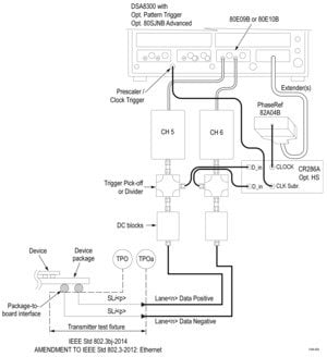
Transmitter test fixture and test points
IEEE 802.3bj (100GBASE-CR4) Electrical Transmitter Measurements fully automated
| Parameter | Subclause reference | Value | Units |
|---|---|---|---|
| Differential peak-to-peak output voltage (max) with Tx disabled | 92.8.3.1 | 35 | mV |
| DC common-mode output voltage (max) | 92.8.3.1 | 1.9 | V |
| AC common-mode output voltage, vcmi (max., RMS) | 92.8.3.1 | 30 | mV |
| Differential peak-to-peak voltage, vdi (max.) | 92.8.3.1 | 1200 | mV |
| Transmitter waveform | |||
| Transmitter steady-state voltage, vf (min.) | 92.8.3.5.2 | 0.34 | V |
| Transmitter steady-state voltage, vf (max.) | 92.8.3.5.2 | 0.6 | V |
| Linear fit pulse peak (min.) | 92.8.3.5.2 | 0.45 × vf | V |
| Transmitted waveform | |||
| abs coefficient step size (min.) | 92.8.3.5.4 | 0.0083 | - |
| abs coefficient step size (max.) | 92.8.3.5.2 | 0.05 | - |
| minimum precursor full-scale ratio | 92.8.3.5.5 | 1.54 | - |
| minimum post cursor full-scale ratio | 92.8.3.5.5 | 4 | - |
| Signal-to-noise-and-distortion ratio (min.) | 92.8.3.5.7 | 26 | dB |
| Output jitter (max.) | |||
| Even-odd jitter, peak-to-peak | 92.8.3.8.1 | 0.035 | UI |
| Effective bounded uncorrelated jitter, peak-to-peak | 92.8.3.8.2 | 0.1 | UI |
| Effective total uncorrelated jitter, peak-to-peak | 92.8.3.8.2 | 0.18 | UI |
| Signaling rate, per lane | 92.8.3.9 | 25.78125±100 ppm | GBd |
| Unit interval nominal | 92.8.3.9 | 38.787879 | ps |

Transmitter test fixture and test points
IEEE 802.3bm (CAUI-4) Electrical Transmitter Measurements fully automated
| Parameter | Subclause reference | Value | Units |
|---|---|---|---|
| Signaling rate per lane (range) | 83E.3.1.1 | 25.78125 ± 100 ppm | GBd |
| DC common-mode output voltage (max) | 83E.3.1.2 | 2.8 | V |
| DC common-mode output voltage (min) | 83E.3.1.2 | –0.3 | V |
| Single-ended output voltage (max) | 83E.3.1.2 | 3.3 | V |
| Single-ended output voltage (min) | 83E.3.1.2 | –0.4 | V |
| AC common-mode output voltage (max, RMS) | 83E.3.1.2 | 17.5 | mV |
| Differential peak-to-peak output voltage (max) | |||
| Transmitter disabled | 83E.3.1.2 | 35 | mV |
| Transmitter enabled | 83E.3.1.2 | 900 | mV |
| Eye width (min) | 83E.3.1.6 | 0.46 | UI |
| Eye height A, differential (min) | 83E.3.1.6 | 95 | mV |
| Eye height B, differential (min) | 83E.3.1.6 | 80 | mV |
| Transition time (min, 20% to 80%) | 83E.3.1.5 | 10 | ps |
| Parameter | Subclause reference | Value | Units |
|---|---|---|---|
| Signaling rate per lane (range) | 83E.3.1.1 | 25.78125 ± 100 ppm | GBd |
| AC common-mode output voltage (max, RMS) | 83E.3.1.2 | 17.5 | mV |
| Differential output voltage (max) | 83E.3.1.2 | 900 | mV |
| Eye width (min) | 83E.3.2.1 | 0.57 | UI |
| Eye height, differential (min) | 83E.3.2.1 | 228 | mV |
| Vertical eye closure (max) | 83E.4.2.1 | 5.5 | dB |
| Transition time (min, 20% to 80%) | 83E.3.1.5 | 12 | ps |
| DC common mode voltage (min) 1 | 83E.3.1.2 | –350 | mV |
| DC common mode voltage (max) 1 | 83E.3.1.2 | 2850 | mV |

Transmitter test fixture and test points
Host Control Board (HCB) and Module Control Board (MCB) are for test point TP1a and TP4 respectively.
1DC common mode voltage is generated by the host. Specification includes effects of ground offset voltage.
Electrical System Interconnect Setup
Direct electrical connections via a precision fixture or 2.92mm interconnects are the preferred method to access the backplane and cabled signals. The QSFP28 module interconnect point found on 100GBASE-CR4 and CAUI-4 designs is the most typical signal access point.

Refer to Wilder Technologieswww.wilder-tech.com/qsfp-28-kits.htmfor details regarding the various methods of signal break-out.
100GBASE-KR4/100GBASE-CR4 Measurement Selection
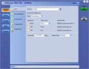
The setup and test execution are simple with the 100G-TXE software. The oscilloscope acquisition and analysis are all controlled through the 100G-TXE automation solution. The Graphical User Interface (GUI) provides an intuitive and easily repeatable workflow for setup and testing.

TekExpress ® 100GBASE-KR4 measurement setup
Design characterization is supported beyond 100GBASE-KR4/100GBASE-CR4/CAUI-4 compliance requirements for all measurements. TekExpress 100G-TXE offers flexible control over test configurations such as analysis windows and other parameters. User defined mode lets customers make changes to the test limits, and perform marginal testing beyond compliance.
User Defined mode
Users can configure global parameters, test specific parameters, measurement repeat parameters, and notification parameters in user defined mode. This supports characterization measurements rather than developing custom lab setups, reducing testing time and complexity.

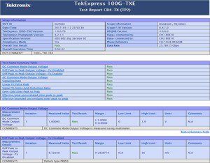
Reports & Measurement Results


Ordering Information
IEEE-802.3bm CAUI4 and IEEE-802.3bj 100GBASE-KR4/100GBASE-CR4 Electrical Equivalent Time Transmitter Compliance and Characterization Solution for DSA8300
- To order with oscilloscope
- Oscilloscope Option DSA8300 Order 80S100G-TXE
- To upgrade an oscilloscope
-
Oscilloscope Option DSA8300 DSA83UP 80S100G-TXE
Software options
- Option 80S100G-TXE
- IEEE-802.3bm CAUI4 and IEEE-802.3bj 100GBASE-KR4/100GBASE-CR4 Electrical Equivalent Time Transmitter Compliance and Characterization Solution for DSA8300
- Option JNB02
- 80SJNB Advanced (With SDLA)
- Option ADVTRIG
- Advanced triggers with pattern sync
Recommended accessories
- 80A08
- Accessory kit
Recommended products
- BERTScope clock recovery
- CR286A
- Remote sampling oscilloscope module
- 80E07/B, 80E08/B, 80E09/B, 80E10/B
- Phase reference module
- 82A04B - 8000 Series
- Module extender cables
- 80X01 & 80X02 (1 each)


