This post and follow on posts will offer up essential information on performing line sweeping measurements on cable and antenna systems using a spectrum analyzer and a tracking generator, including a look at why these measurements are important and how to perform them. Specific topics covered include return loss/voltage standing wave ratio (VSWR), cable loss, antenna location, and distance to fault (DTF) measurements.
Tracking generators are what allow spectrum analyzers to perform transmission loss, transmission gain and return loss measurements. Tracking generators are simply variable, or swept, RF generators that track with the spectrum analyzer sweep frequency. In other words, the tracking generator produces signals as the analyzer sweeps, measuring power across a frequency range. This allows the user to provide a known stimulus to a circuit and view the response.
There are many spectrum analyzers on the market today with tracking generators. However, most of this equipment is battery powered and intended for field applications. Because of this constraint, they incorporate slow, low-power processors and offer limited to no real-time capabilities. Tektronix USB spectrum analyzers, on the other hand, work in conjunction with a laptop or tablet PC to offer desktop-level real-time performance in an easily portable package.
What can go wrong?
It’s estimated that about 60 percent of cellular base station problems result from faulty cables, connectors and antennas. Some problems occur during installation and are immediately apparent. But over time, these components may become damaged or gradually degrade. Such failures often result in poor coverage and unnecessary handovers in the case of cellular systems. Cellular is the most obvious and pervasive example, but any communication system is bound to degrade without ongoing testing to verify performance and isolate the source of problems.
Cabling and antennas are expected to cope with a diverse range of environments including outdoor and indoor installations, each posing different challenges.
Typical outdoor installations involve mounting antennas on the tops of tall buildings or on towers, often in remote locations, where the antenna and portions of the coaxial cabling can be exposed to extreme weather conditions including wide temperature swings, rain, snow, ice, wind and lightning. Such conditions can exact a major toll on the integrity of the system, resulting in physical damage such as failed waterproofing at connector joints, failed cable splice seals, and cracks in insulating materials.
Indoor installations range from stationary set-ups like equipment shelters and office building to more mobile (and therefore more vulnerable) applications on ships, airplanes and trains, as well as cars and trucks. Even sheltered installations face a range of hazards including mishandling, stress, heat, vibration, chemicals and contamination. Problems are especially prevalent at solder joints and cable crimps that tend to weaken over time and break or degrade.
Running cables up and down towers, through walls or underground can be a messy job. It’s not hard to tear, stretch, dent, crush or poorly rout a cable during installation – problems that can sometimes manifest themselves long after the initial installers have moved on. Other problems occur when the minimum bend radius is exceeded such as in the case of low-loss coaxial cables, which can significantly degrade electrical performance.
Fortunately, it’s not necessary to use highly specialized tools for cable and antenna test and troubleshooting. Portable spectrum analyzers are already used in the installation and maintenance of RF transmission systems, and are already used to test many different aspects of a RF transmission system, from overall performance to analysis of individual components. Therefore, adding a tracking generator to a spectrum analyzer is a cost-effective solution to the problem.
Tracking generator basics
Since spectrum analyzers receive and measure a signal, they can be considered passive instruments. As such, spectrum analyzers by themselves are not able to make cable and antenna measurements that require known signals, such as that from a tracking generator to be applied to a device or network under test to measure the output or response.
There are two main types of test equipment used for making these stimulus-response measurements. The traditional type of test equipment is an RF or scalar network analyzer. The other option is a spectrum analyzer with a tracking generator. A vector network analyzer is typically required if exceptional accuracy is needed, but in most other cases a spectrum analyzer and tracking generator arrangement is an excellent solution. This is particularly true with the advent of low-cost high-performance USB-based spectrum analyzers.
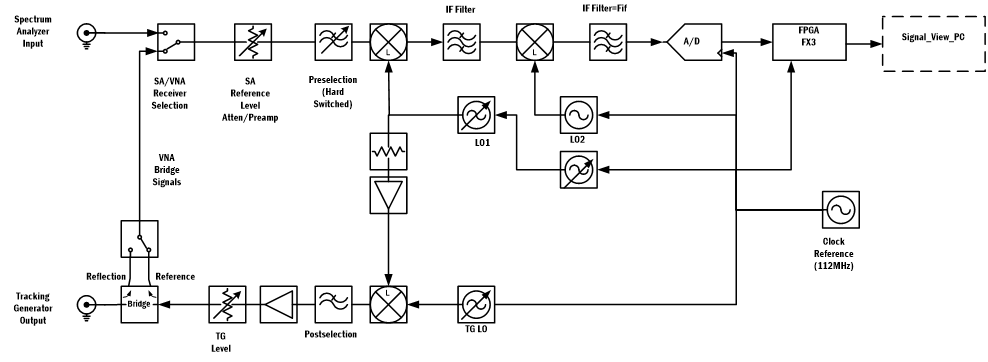
The tracking generator operates by providing a sinusoidal output to the input of the spectrum analyzer. By linking the sweep of the tracking generator to the spectrum analyzer using a return loss bridge, the output of the tracking generator is on the same frequency as the spectrum analyzer, and the two units track the same frequency as shown below.

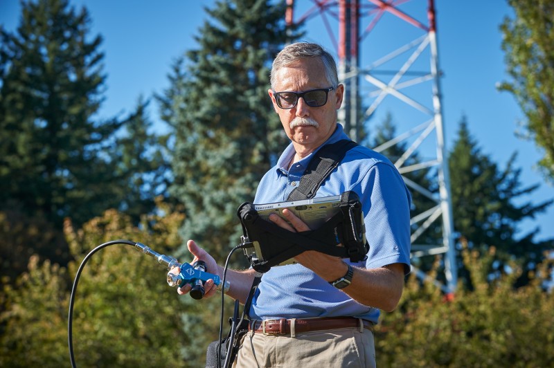
RSA500/600 Series spectrum analyzer with optional tracking generator.
Connecting the output of the tracking generator to the input of the spectrum analyzer, such as during normalization, results in a single flat line, with the level representing the reference loss of the direct connection. For measurements, an unknown device is placed between the output of the tracking generator and the input of the spectrum analyzer. The response of the device under test alters the signal and this change is then measured by the spectrum analyzer.
Normalization, calibration, measurements
Tracking generators in spectrum analyzers may either make purely scalar measurements, or they may measure vector parameters. For transmission gain measurements, the RSA500 and RSA600 uses a scalar normalization of the measured power to create a normalized display of frequency vs. amplitude. For vector measurements such as return loss, VSWR, cable loss and distance-to-fault, a vector calibration is required. The RSA500 and RSA600 are shipped with a factory vector calibration that is useful for many troubleshooting applications, and can be fully user-calibrated using an Open, Short, Load (OSL) method for greater accuracy. More information on calibration techniques can be found in the user help files for SignalVu-PC. All of the vector measurements made in this blog were performed using the factory calibration in the instrument.
Tektronix RSA500, RSA600
The RSA500 series was built to bring real-time spectrum analysis to solving the problems of spectrum managers, interference hunters, and network maintenance personnel who need to track down hard to find interferers, maintain RF networks and keep records of their efforts. The RSA500 offers rugged, compact packaging and optional battery power. The RSA600 offers the same capabilities, but in a line-powered enclosure well suited for lab environments. Both are small form factor, high performance spectrum analyzers with tracking generator capabilities.
The heart of both systems is a USB-based RF spectrum analyzer that captures 40 MHz bandwidths with exceptional fidelity. With 70 dB dynamic range and frequency coverage to 7.5 GHz, all signals of interest can be examined with high confidence in measurement results. The USB form factor moves the weight of the portable instrument off your hands, and replaces it with a lightweight Windows tablet or laptop.
The RSA500 and RSA600 series operate with SignalVu-PC software, a powerful program used as the basis of Tektronix’s traditional spectrum analyzers, offering a deep analysis capability previously unavailable in high performance battery-operated solutions. Real-time processing of the DPX spectrum/spectrogram is enabled in a PC, further reducing the cost of hardware.
Thanks to its integrated return loss bridge, the optional tracking generator enables gain/loss measurements for quick tests of filters, duplexers and other network elements as well as cable and antenna measurements such as VSWR, return loss, distance to fault and cable loss. In addition to this, Tektronix offers an array of calibration kits and accessories to help ensure precise and accurate measurements can be taken.
The next post in this series will look at cable and antenna loss measurements such as return loss, VSWR, and cable loss. We’ll also touch on co-located antennas and how to measure isolation to keep intermodulation and desensitization products from occurring. Learn more about RSA500 Series »