Document #SPEC-DMM7510C
Specifications are subject to change without notice.
SPECIFICATION CONDITIONS
This document contains specifications and supplemental information for the Model DMM7510 7-1/2 Digit Graphical Sampling Multimeter instrument. Specifications are the standards against which the DMM7510 is tested. Upon leaving the factory, the DMM7510 meets these specifications. Supplemental and typical values are nonwarranted, apply at 23 °C, and are provided solely as useful information.
Measurement accuracies are specified at the DMM7510 terminals under these conditions:
- Temperature 23 °C ±5 °C, 5% to 80% relative humidity, noncondensing
- After a 90-minute warmup period
- 1 PLC or 5 PLC measurement rate; for NPLC settings less than 1 PLC, add appropriate ppm of range for peak noise uncertainty from the RMS noise table
- Autozero enabled unless otherwise noted
- Remote sense operation or properly zeroed local operation
- Calibration period: One year or two years (calibration period may vary depending on customer requirements)
Definitions:
- TACAL: Ambient temperature of last automatic calibration
- TCAL: Ambient temperature of last external calibration; factory calibration performed at 23 °C ±1 °C
- Power Line Cycle (PLC): 16.67 ms at 60 Hz and 20 ms at 50 Hz or 400 Hz line frequency; frequency automatically sensed at power up
DC VOLTAGE
ACCURACY (INPUT IMPEDANCE AUTO)
| Range1 | Resolution | Input impedance | Accuracy ±[ppm of reading + ppm of range] | ||||
| 24 hour TCAL ±1 °C2 | 90 day TCAL ±5 °C | 1 year TCAL ±5 °C | 2 year TCAL ±5 °C | Temperature coefficient3 | |||
| 100 mV4 | 10 nV | > 10 GΩ or 10 MΩ ±1% | 6 + 9 | 12 + 9 | 18 + 9 | 29 + 9 | 0.1 + 2.5 |
| 1 V4 | 100 nV | > 10 GΩ or 10 MΩ ±1% | 4 + 1 | 9 + 2 | 15 + 2 | 26 + 2 | 0.1 + 0.5 |
| 10 V4 | 1 µV | > 10 GΩ or 10 MΩ ±1% | 2 + 0.7 | 9 + 1.2 | 14 + 1.2 | 22 + 1.2 | 0.1 + 0.05 |
| 100 V4 | 10 µV | 10 MΩ ±1% | 8 + 3 | [18 + 5]5 | [22 + 5]5 | [30 + 5]5 | [0.15 + 0.05]5 |
| 35 + 5 | 40 + 5 | 45 + 5 | 2.0 + 0.5 | ||||
| 1000 V4, 6 | 100 µV | 10 MΩ ±1% | 8 + 3 | [19 + 5]5 | [23 + 5]5 | [31 + 5]5 | [0.15 + 0.05]5 |
| 35 + 5 | 40 + 5 | 45 + 4 | 2.0 + 0.5 | ||||
1 20% overrange on all ranges except 1% for 1000 V range.
2 Relative to calibration accuracy.
3 Add per degree from TCAL ± 5 °C.
4 When properly zeroed using the Rel function with external cables.
5 Specified within 30 days of autocalibration, TOPER ± 5 °C from TACAL.
6 For signal levels greater than 500 V, add 0.02 ppm/V to the ppm of the readings specification for measurements exceeding 500 V.
RMS NOISE (ADDITIONAL PEAK NOISE UNCERTAINTY)7
|
||||||
| NPLC | Digits | 100 mV | 1 V | 10 V | 100 V | 1000 V |
| 5 | 7½ | 0.83 | 0.09 | 0.07 | 0.41 | 0.07 |
| 5 | 7½ | 0.73 | 0.13 | 0.09 | 0.56 | 0.10 |
| 0.28 | 6½ | 2.51 (10) | 0.28 (1.6) | 0.17 (1.1) | 1.45 (9.4) | 0.20 (1) |
| 0.2 | 6½ | 3.16 (12) | 0.34 (1.6) | 0.18 (1) | 1.42 (8.9) | 0.20 (1.1) |
| 0.06 | 5½ | 4.09 (17) | 0.53 (2.7) | 0.38 (2.1) | 3.41 (17) | 0.47 (2.4) |
| 0.006 | 4½ | 7.30 (42) | 3.80 (18) | 2.79 (11) | 28.63 (100) | 3.98 (18) |
| 0.0005 | 3½ | 39.41 (220) | 27.24 (150) | 33.71 (130) | 151.05 (690) | 40.63 (150) |
7 Noise values are based on 1000 readings with autozero on and using low thermal 4-wire short. VRMS noise is typical. Additional peak noise is guaranteed.
8 With line sync on.
DC VOLTAGE SENSE ACCURACY
| Range | Accuracy ±[ppm of reading + ppm of range] | ||||
| 24 hour TCAL ±1 °C | 90 day TCAL ±5 °C | 1 year TCAL ±5 °C | 2 year TCAL ±5 °C | Temperature coefficient9 | |
| 100 mV | 6 + 14 | 12 + 14 | 18 + 14 | 29 + 14 | 0.1 + 2.5 |
| 1 V | 4 + 1.5 | 9 + 3 | 15 + 3 | 26 + 3 | 0.1 + 0.5 |
| 10 V | 2 + 1.0 | 9 + 1.8 | 14 + 1.8 | 22 + 1.8 | 0.1 + 0.05 |
9 Add per degree from TCAL ± 5 °C.
DC VOLTAGE RATIO
| For input signals ≥ 1% of the range, ratio accuracy = |
±[[VINPUT ppm of reading + VINPUT ppm of range * (VINPUT range/VINPUT input)] + [VSENSE ppm of reading + VSENSE ppm of range * (VSENSE range/VSENSE input)]] |
DC VOLTAGE CHARACTERISTICS
| ADC linearity | 1.0 ppm of reading + 1.0 ppm of range |
| Input impedance |
100 mV to 10 V ranges: Selectable > 10 GΩ ǁ < 400 pF (auto) or 10 MΩ ±1% (10 MΩ) 100 V to 1000 V ranges: 10 MΩ ±1% |
| Input bias current | < 50 pA at 23 °C under the following conditions: Autozero off or input impedance 10 MΩ |
| Common mode current | < 2.1 µA peak-peak in 1 MHz bandwidth < 100 nA peak-peak in 1 kHz bandwidth |
| Common mode voltage | 500 VPEAK LO terminal to chassis maximum |
| Autozero off error, dc voltage | For ±1 °C and ≤ 10 minutes, add ± (8 ppm of reading + 15 µV) |
NORMAL MODE REJECTION
For dc voltage, line frequency ±0.1%
| 5 PLC | 1 PLC | ≤ 0.2 PLC | ≤ 0.01 PLC | |
| Line sync on | 110 dB | 90 dB | 45 dB | — |
| Line sync off | 60 dB | 60 dB | — | — |
COMMON MODE REJECTION
For dc voltage and 1 kΩ unbalanced in LO terminal; AC CMRR is 70 dB
| NPLC | 5 | 1 | 0.2 | ≤ 0.2 |
| Line sync | On | On | On | Off |
| CMRR | 140 dB | 140 dB | 120 dB | 80 dB |
RESISTANCE
ENHANCED ACCURACY (WITHIN 30 DAYS OF AUTOCALIBRATION, TOPER ± 5 °C FROM TACAL)10
| Range11 | Resolution | Test current12 (± 5%) | Accuracy ±[ppm of reading + ppm of range] | ||||
| 24 hour TCAL ±1 °C13 | 90 day TCAL ±5 °C | 1 year TCAL ±5 °C | 2 year TCAL ±5 °C | Temperature coefficient14 | |||
| 1 Ω | 0.1 µΩ | 10 mA | 15 + 50 | 30 + 50 | 30 + 50 | 30 + 50 | 0.15 + 0.1 |
| 10 Ω | 1 µΩ | 10 mA | 15 + 5 | 30 + 5 | 30 + 5 | 30 + 5 | 0.15 + 0.1 |
| 100 Ω | 10 µΩ | 1 mA | 12 + 4 | 27 + 4 | 27 + 4 | 27 + 4 | 0.15 + 0.1 |
| 1 kΩ | 100 µΩ | 1 mA | 12 + 3 | 24 + 3 | 24 + 3 | 24 + 3 | 0.15 + 0.1 |
| 10 kΩ15 | 1 mΩ | 100 µA | 13 + 3 | 30 + 3 | 30 + 3 | 30 + 3 | 0.15 + 0.1 |
| 100 kΩ15,16 | 10 mΩ | 10 µA | 13 + 3 | 30 + 3 | 30 + 3 | 30 + 3 | 0.15 + 0.1 |
| 1 MΩ15,17 | 100 mΩ | 10 µA | 28 + 3 | 60 + 4 | 60 + 4 | 60 + 4 | 0.15 + 0.1 |
| 10 MΩ18 | 1 Ω | 0.69 µA ǁ 10 MΩ | 150 + 6 | 200 + 10 | 200 + 10 | 200 + 10 | 70 + 1 |
| 100 MΩ18 | 10 Ω | 0.69 µA ǁ 10 MΩ | 800 + 30 | 2000 + 30 | 2000 + 30 | 2000 + 30 | 385 + 1 |
| 1 GΩ18 | 100 Ω | 0.69 µA ǁ 10 MΩ | 9000 + 100 | 9000 + 100 | 9000 + 100 | 9000 + 100 | 3000 + 1 |
10 Specifications are for 4-wire resistance, offset compensation on for ≤10 kΩ measurements, and offset compensation off for ≥10 kΩ measurements. 1 Ω range is 4-wire only. For 2-wire, with Rel, add 50 mΩ to ppm of range uncertainty. Without Rel and with Model 1756 test leads, add 100 mΩ to ppm of range uncertainty.
11 20% overrange on all ranges.
12 Test current with offset compensation off.
13 Relative to calibration accuracy.
14 Add per degree from TCAL ±5 °C.
15 Specifications are for external cable and load capacitance < 1 nF.
16 For offset compensation on, add 10 ppm uncertainty to ppm of reading.
17 For 4-wire 1 MΩ, open lead detector on, add 10 ppm uncertainty to ppm of reading.
18 Specified for < 10% lead resistance mismatch in HI and LO.
ACCURACY19
| Range20 | Resolution | Test current21 (± 5%) | Accuracy ±[ppm of reading + ppm of range] | ||||
| 24 hour TCAL ±1 °C13 |
90 day TCAL ±5 °C |
1 year TCAL ±5 °C |
2 year TCAL ±5 °C |
Temperature coefficient23 | |||
| 1 Ω | 0.1 µΩ | 10 mA | 15 + 50 | 40 + 50 | 50 + 50 | 70 + 50 | 2.5 + 5 |
| 10 Ω | 1 µΩ | 10 mA | 15 + 5 | 40 + 5 | 50 + 5 | 70 + 5 | 2.5 + 0.5 |
| 100 Ω | 10 µΩ | 1 mA | 12 + 4 | 35 + 4 | 47 + 4 | 65 + 4 | 5 + 0.25 |
| 1 kΩ | 100 µΩ | 1 mA | 12 + 3 | 30 + 3 | 41 + 3 | 65 + 3 | 5 + 0.25 |
| 10 kΩ24 | 1 mΩ | 100 µA | 10 + 3 | 30 + 3 | 42 + 3 | 65 + 3 | 2.5 + 0.25 |
| 100 kΩ24,25 | 10 mΩ | 10 µA | 13 + 3 | 38 + 3 | 50 + 3 | 65 + 3 | 5 + 1 |
| 1 MΩ24,26 | 100 mΩ | 10 µA | 28 + 3 | 75 + 5 | 100 + 5 | 130 + 5 | 5 + 1 |
| 10 MΩ27 | 1 Ω | 0.69 µA ǁ 10 MΩ | 150 + 6 | 200 + 10 | 400 + 10 | 600 + 12 | 70 + 1 |
| 100 MΩ27 | 10 Ω | 0.69 µA ǁ 10 MΩ | 800 + 30 | 2000 + 30 | 2000 + 30 | 2600 + 30 | 385 + 1 |
| 1 GΩ27 | 100 Ω | 0.69 µA ǁ 10 MΩ | 9000 + 200 | 9000 + 200 | 13000 + 200 | 14000 + 200 | 3000 + 1 |
RESISTANCE OPEN CIRCUIT DC VOLTAGE28
| Range20 | 2-wire | Offset compensation off 4-wire | Offset compensation on 4-wire |
| 1 Ω | ‐ | 9.2 V | 9.5 V |
| 10 Ω | 9.2 V | 9.2 V | 9.5 V |
| 100 Ω, 1 kΩ | 14.0 V | 14.2 V | 14.3 V |
| 10 kΩ | 9.5 V | 9.5 V | 0.0 V |
| 100 kΩ, 1 MΩ | 12.7 V | 14.3 V | 0.0 V (100 kΩ range only) |
| 10 MΩ to 1 GΩ | 6.9 V | 6.9 V | ‐ |
19 Specifications are for 4-wire resistance, offset compensation on for ≤10 kΩ measurements, and offset compensation off for ≥10 kΩ measurements. 1 Ω range is 4-wire only. For 2-wire, with Rel, add 50 mΩ to ppm of range uncertainty. Without Rel and with Model 1756 test leads, add 100 mΩ to ppm of range uncertainty.
20 20% overrange on all ranges.
21 Test current with offset compensation off.
22 Relative to calibration accuracy.
23 Add per degree from TCAL ±5 °C.
24 Specifications are for external cable and load capacitance < 1 nF.
25 For offset compensation on, add 10 ppm of uncertainty to ppm of reading.
26 For 4-wire, 1 MΩ, open lead detection on, add 10 ppm uncertainty to ppm of reading.
27 Specified for < 10% lead resistance mismatch in HI and LO.
28 Open circuit voltage is typical, measured from input HI to LO, SHI and SLO open. For 1 Ω to 1 MΩ ranges using an external digital multimeter (DMM) set to 10 MΩ input impedance; for 10 MΩ to 1 GΩ ranges, set external DMM to >10 GΩ input impedance.
4-WIRE OHMS (≤ 10 kΩ) OFFSET COMPENSATION ON
RMS NOISE (ADDITIONAL PEAK NOISE UNCERTAINTY)29
|
||||||
| NPLC | Digits | 1 Ω | 10 Ω | 100 Ω | 1 kΩ | 10 kΩ |
| 5 | 7½ | 3.49 | 0.35 | 0.35 | 0.08 | 0.35 |
| 1 | 7½ | 7.81 | 0.79 | 0.78 | 0.16 | 0.78 |
| 0.230 | 6½ | 51.87 (160) | 5.09 (13) | 5.21 (13) | 0.61 (2.6) | 1.78 (8.2) |
| 0.2 | 6½ | 68.32 (250) | 6.76 (22) | 6.8 (22) | 0.85 (3.2) | 1.78 (8.3) |
| 0.06 | 5½ | 123.35 (490) | 12.33 (47) | 12.36 (46) | 1.30 (6.6) | 3.48 (16) |
| 0.006 | 4½ | 140.23 (710) | 14.53 (70) | 14.20 (70) | 4.87 (26) | 14.14 (60) |
| 0.0005 | 3½ | 676.58 (3420) | 67.39 (340) | 67.86 (340) | 46.48 (220) | 58.49 (300) |
2-WIRE OHMS
RMS NOISE (ADDITIONAL PEAK NOISE UNCERTAINTY)29
|
||||||
| NPLC | Digits | 10 Ω | 100 Ω | 1 kΩ | 10 kΩ | |
| 5 | 7½ | 1.35 | 0.89 | 0.15 | 0.26 | |
| 1 | 7½ | 0.78 | 0.77 | 0.11 | 0.55 | |
| 0.230 | 6½ | 2.73 (17) | 2.82 (10) | 0.30 (1.5) | 1.27 (6.3) | |
| 0.2 | 6½ | 3.27 (17) | 3.29 (14) | 0.33 (1.6) | 1.27 (6.4) | |
| 0.06 | 5½ | 4.28 (22) | 4.21 (19) | 0.51 (3.7) | 2.38 (12) | |
| 0.006 | 4½ | 7.79 (50) | 8.17 (50) | 3.58 (21) | 9.49 (43) | |
| 0.0005 | 3½ | 40.76 (300) | 51.31 (230) | 27.82 (150) | 34.53 (210) | |
29 Noise values are based on 1000 readings with autozero on and using low thermal 4-wire short. RMS noise is typical. Additional peak noise is guaranteed.
30 With line sync on.
RESISTANCE CHARACTERISTICS
| Maximum 4-wire ohms lead resistance | 5 Ω per lead for 1 Ω range, 10% of range per lead for 10 Ω to 1 kΩ ranges; 1 kΩ per lead for all other ranges |
| Offset compensation | Selectable on 4-wire, 1 Ω to 100 kΩ ranges |
| Open lead detector | Default is off |
| Autozero off error | For 2-wire ohms, ±1 °C and ≤ 10 minutes, add ±(8 ppm of reading) and 1.5 mΩ for 10 Ω range, 15 mΩ for 100 Ω and 1 kΩ ranges, 150 mΩ for 10 kΩ range, 1.5 Ω for 100 kΩ range, and 15 Ω for all other ranges For 4-wire ohms, ±1 °C and ≤ 10 minutes, add ±(8 ppm of reading) |
| Input current limit |
For signals with a magnitude of +12 V to +40 V or −12 V to −40 V: ±13 mA source or sink, typical For signals with a magnitude of greater than +40 V or −40 V: ±130 µA source or sink, typical |
DRY CIRCUIT RESISTANCE
ENHANCED ACCURACY (WITHIN 30 DAYS OF AUTOCALIBRATION, TOPER ±5 ºC FROM TACAL)
| Range31 | Resolution | Test current35 (±5%) | Open circuit DUT voltage32 | Accuracy ±[ppm of reading + ppm of range] | ||||
| 24 hour TCAL ±1 °C33 |
90 day TCAL ±5 °C |
1 year TCAL ±5 °C |
2 year TCAL ±5 °C |
Temperature coefficient34 | ||||
| 1 Ω | 1 µΩ | 10 mA | 25 mV | 25 + 80 | 50 + 80 | 50 + 80 | 50 + 80 | 1.5 + 0.1 |
| 10 Ω | 10 µΩ | 1 mA | 25 mV | 25 + 80 | 50 + 80 | 50 + 80 | 50 + 80 | 1.5 + 0.1 |
| 100 Ω | 100 µΩ | 100 µA | 25 mV | 25 + 80 | 90 + 80 | 90 + 80 | 90 + 80 | 1.5 + 0.1 |
| 1 kΩ | 1 mΩ | 10 µA | 25 mV | 25 + 80 | 180 + 80 | 180 + 80 | 180 + 80 | 1.5 + 0.1 |
| 10 kΩ | 10 mΩ | 5 µA | 25 mV | 25 + 80 | 320 + 80 | 320 + 80 | 320 + 80 | 1.5 + 0.1 |
ACCURACY
| Range31 | Resolution | Test current35 (±5%) |
Open circuit DUT voltage32 | Accuracy ±[ppm of reading + ppm of range] | ||||
| 24 hour TCAL ±1 °C33 |
90 day TCAL ±5 °C |
1 year TCAL ±5 °C |
2 year TCAL ±5 °C |
Temperature coefficient34 | ||||
| 1 Ω | 1 µΩ | 10 mA | 25 mV | 25 + 80 | 50 + 80 | 70 + 80 | 90 + 80 | 2.5 + 1 |
| 10 Ω | 10 µΩ | 1 mA | 25 mV | 25 + 80 | 50 + 80 | 70 + 80 | 90 + 80 | 5 + 1 |
| 100 Ω | 100 µΩ | 100 µA | 25 mV | 25 + 80 | 90 + 80 | 140 + 80 | 200 + 80 | 2.5 + 1 |
| 1 kΩ | 1 mΩ | 10 µA | 25 mV | 25 + 80 | 180 + 80 | 400 + 80 | 600 + 80 | 5 + 1 |
| 10 kΩ | 10 mΩ | 5 µA | 25 mV | 25 + 80 | 320 + 80 | 800 + 80 | 1300 + 80 | 8 + 1 |
31 20% overrange on all ranges, except 2.4 kΩ for the 10 K range.
32 Maximum clamp voltages are dc, typical accuracy is ±20%. Add 20% for offset compensation on.
33 Relative to calibration accuracy.
34 Add per degree from TCAL ±5 °C.
35 Test current with offset compensation off.
RMS NOISE (ADDITIONAL PEAK NOISE UNCERTAINTY)36
|
||||||
| NPLC | Digits | 1 Ω | 10 Ω | 100 Ω | 1 kΩ | 10 kΩ |
| 5 | 7½ | 10.00 | 11.00 | 6.00 | 5.00 | 0.90 |
| 1 | 7½ | 10.90 | 10.70 | 12.41 | 11.84 | 1.72 |
| 0.237 | 6½ | 50.50 (130) | 51.44 (120) | 52.76 (120) | 49.96 (120) | 8.83 (16) |
| 0.2 | 6½ | 88.50 (220) | 90.19 (230) | 88.69 (190) | 83.66 (190) | 15.01 (35) |
| 0.06 | 5½ | 94.29 (350) | 94.73 (350) | 72.20 (290) | 68.32 (280) | 23.30 (90) |
| 0.006 | 4½ | 159.87 (750) | 154.33 (830) | 144.15 (700) | 137.71 (690) | 27.27 (110) |
| 0.0005 | 3½ | 657.22 (3550) | 666.79 (3520) | 678.67 (3380) | 655.82 (3370) | 131.78 (670) |
DRY CIRCUIT RESISTANCE CHARACTERISTICS
| Maximum 4-wire ohm lead resistance |
0.5 Ω per lead for 1 Ω range 10% of range per lead for 10 Ω to 100 Ω ranges 50 Ω per lead for 1 kΩ to 10 kΩ ranges |
| Input current limit | For signals > [±20 mV], current limited, ±13 mA, typical |
| Offset compensation | Selectable on 1 Ω to 10 kΩ ranges |
| Autozero off error | For ±1 °C and ≤ 10 minutes, add ± 8 ppm of reading |
36 Noise values are based on 1000 readings with autozero on and using low thermal 4-wire short. RMS noise is typical. Additional peak noise is guaranteed.
37 With line sync on.
DC CURRENT
ENHANCED ACCURACY (WITHIN 30 DAYS OF AUTOCALIBRATION, TOPER ± 5 °C FROM TACAL)
| Range38 | Resolution | Maximum burden voltage |
Accuracy ±[ppm of reading + ppm of range] | ||||
| 24 hour TCAL ±1 °C39 |
90 day TCAL ±5 °C |
1 year TCAL ±5 °C |
2 year TCAL ±5 °C |
Temperature coefficient40 | |||
| 10 µA | 1 pA | 15 mV | 30 + 30 | 75 + 30 | 75 + 30 | 75 + 30 | 0.15 + 1 |
| 100 µA | 10 pA | 15 mV | 20 + 5 | 60 + 9 | 60 + 9 | 60 + 9 | 0.15 + 1 |
| 1 mA | 100 pA | 15 mV | 30 + 5 | 60 + 9 | 60 + 9 | 60 + 9 | 0.15 + 1 |
| 10 mA | 1 nA | 20 mV | 40 + 5 | 60 + 9 | 60 + 9 | 60 + 9 | 0.15 + 1 |
| 100 mA | 10 nA | 200 mV | 50 + 18 | 150 + 30 | 150 + 30 | 150 + 30 | 0.15 + 1 |
| 1 A | 100 nA | 400 mV | 150 + 50 | 400 + 50 | 400 + 50 | 400 + 50 | 0.15 + 1 |
| 3 A | 1 µA | 1300 mV | 200 + 40 | 400 + 40 | 400 + 40 | 400 + 40 | 0.15 + 1 |
| 10 A41 | 1 µA | 650 mV | 700 + 275 | 800 + 275 | 1500 + 275 | 2000 + 275 | 50 + 10 |
ACCURACY
| Range38 | Resolution | Maximum burden voltage |
Accuracy ±[ppm of reading + ppm of range] | ||||
| 24 hour TCAL ±1 °C39 |
90 day TCAL ±5 °C |
1 year TCAL ±5 °C |
2 year TCAL ±5 °C |
Temperature coefficient40 | |||
| 10 µA | 1 pA | 15 mV | 30 + 30 | 100 + 30 | 125 + 40 | 175 + 50 | 10 + 8 |
| 100 µA | 10 pA | 15 mV | 20 + 5 | 75 + 12 | 100 + 15 | 150 + 20 | 10 + 3 |
| 1 mA | 100 pA | 15 mV | 30 + 5 | 75 + 12 | 100 + 15 | 150 + 20 | 10 + 3 |
| 10 mA | 1 nA | 20 mV | 40 + 5 | 75 + 12 | 100 + 15 | 150 + 20 | 10 + 3 |
| 100 mA | 10 nA | 200 mV | 50 + 18 | 300 + 30 | 400 + 30 | 500 + 30 | 50 + 5 |
| 1 A | 100 nA | 400 mV | 150 + 50 | 400 + 50 | 450 + 50 | 500 + 50 | 10 + 10 |
| 3 A | 1 µA | 1300 mV | 200 + 40 | 400 + 40 | 450 + 40 | 500 + 40 | 10 + 10 |
| 10 A41 | 1 µA | 650 mV | 700 + 275 | 800 + 275 | 1500 + 275 | 2000 + 275 | 50 + 10 |
38 20% overrange supported for all ranges except for 3 A and 10 A, which are 1% supported.
39 Relative to calibration accuracy.
40 Add per degree from TCAL ±5 °C.
41 Rear input terminals only.
RMS NOISE (ADDITIONAL PEAK NOISE UNCERTAINTY)42
|
|||||||||
| NPLC | Digits | 10 µA | 100 µA | 1 mA | 10 mA | 100 mA | 1 A | 3 A | 10 A43 |
| 5 | 7½ | 0.20 | 0.14 | 0.09 | 0.10 | 0.30 | 0.30 | 0.23 | 0.82 |
| 1 | 7½ | 0.55 | 0.16 | 0.13 | 0.13 | 0.74 | 0.71 | 0.40 | 1.65 |
| 0.244 | 6½ | 2.20 (220) | 0.40 (23) | 0.30 (3.4) | 0.31 (1.6) | 2.41 (10) | 2.40 (11) | 0.89 (4.6) | 5.47 (32) |
| 0.2 | 6½ | 215.45 (260) | 21.43 (26) | 2.10 (3.8) | 0.36 (1.8) | 2.69 (9.8) | 2.97 (10) | 1.09 (5) | 8.88 (37) |
| 0.06 | 5½ | 228.95 (280) | 22.84 (29) | 2.31 (5.6) | 0.57 (3.9) | 3.33 (14) | 3.46 (14) | 1.66 (7.7) | 12.72 (59) |
| 0.006 | 4½ | 233.95 (350) | 23.99 (42) | 3.62 (20) | 2.89 (20) | 6.43 (30) | 6.05 (31) | 8.71 (51) | 20.00 (110) |
| 0.0005 | 3½ | 584.61 (2110) | 62.60 (300) | 28.73 (150) | 28.88 (160) | 34.88 (190) | 35.04 (190) | 91.84 (510) | 74.86 (420) |
42 Noise values are based on 1000 readings with autozero on and AMPS terminal open. RMS noise is typical. Additional peak noise is guaranteed.
| Range | 10 µA | 100 µA | 1 mA | 10 mA | 100 mA | 1 A | 3 A | 10 A43 |
| Effective internal shunt value45 | 1 kΩ | 100 Ω | 10 Ω | 1 Ω | 1 Ω | 0.1 Ω | 0.1 Ω | 0.005 Ω |
| Autozero off error: For ±1 °C and ≤ 10 minutes add ±(8 ppm of reading + range error) | 150 pA | 1.5 nA | 15 nA | 150 nA | 15 µA | 150 µA | 150 µA | 3 mA |
|
Overload recovery: |
15500 | 1800 | 150 | 150 | 6500 | 200 | — | — |
43 Rear input terminals only.
44 With line sync on.
45 Values are typical and guaranteed by design.
TEMPERATURE
4-WIRE RTD OR 3-WIRE RTD
Types: 100 Ω platinum PT100, D100, F100, PT385, PT3916; or user-configurable 0 Ω to 10 kΩ
| Type | Range | Resolution | Accuracy ± °C | |
|
2 year |
Temperature coefficient46 | |||
| 4-Wire RTD | −200 °C to 850 °C | 0.01 °C | 0.06 °C | 0.003 °C /°C |
| 3-Wire RTD47 | −200 °C to 850 °C | 0.01 °C | 0.75 °C | 0.003 °C /°C |
THERMISTOR
Types: 2.252 kΩ, 5 kΩ, and 10 kΩ
| Type | Range | Resolution | Accuracy ± °C | |
| 2 year TCAL ± 5 °C | Temperature coefficient46 | |||
| Thermistor | −80 °C to + 150 °C | 0.01 °C | 0.08 °C | 0.002 °C /°C |
THERMOCOUPLE
Types: B, E, J, K, N, R, S, T
| Type | Range | Resolution | Accuracy ± °C | |
| 2 year TCAL ± 5 °C46 |
Temperature coefficient50 | |||
| B | 350 °C to +1820 °C | 0.1 °C | 0.6 °C | 0.03 °C /°C |
| E | −200 °C to +1000 °C | 0.001 °C | 0.2 °C | 0.03 °C /°C |
| J | −200 °C to +760 °C | 0.001 °C | 0.2 °C | 0.03 °C /°C |
| K | −200 °C to +1372 °C | 0.001 °C | 0.2 °C | 0.03 °C /°C |
| N | −200 °C to +1300 °C | 0.001 °C | 0.2 °C | 0.03 °C /°C |
| R | 0 °C to +1768 °C | 0.1 °C | 0.6 °C | 0.03 °C /°C |
| S | 0 °C to +1768 °C | 0.1 °C | 0.6 °C | 0.03 °C /°C |
| T | −100 °C to +400 °C | 0.001 °C | 0.2 °C | 0.03 °C /°C |
46 Add per degree from TCAL ±5 °C; specifications without autocalibration.
47 For 3-wire RTD, accuracy is for < 0.1 Ω lead resistance mismatch for input HI and LO. Add 0.25 °C/ 0.1 Ω of HI-LO lead resistance mismatch.
48 Exclusive of cold-junction errors.
CONTINUITY
| Range48 | Resolution | Test Current | Open circuit voltage | Accuracy ± [ppm of reading + ppm of range] | |
| 2 year TCAL ± 5 °C |
Temperature coefficient46 | ||||
| 1 kΩ | 100 mΩ | 1 mA | 14.0 V | 100 + 100 | 2.5 + 1 |
CONTINUITY CHARACTERISTICS
| Continuity high limit | User-selectable; default 10 Ω |
CAPACITANCE
Accuracies specified for additional cable and stray capacitance properly zeroed with the Rel function.
ACCURACY
| Range51 | Resolution | Charge current52,53 | Maximum circuit voltage | Accuracy ± [% of reading + % of range] | |
| 2 year TCAL ± 5 °C |
Temperature coefficient50 | ||||
| 1 nF | 0.1 pF | 1.1 µA | 2.8 V | 1 + 0.2 | 0.15 + 0.05 |
| 10 nF | 1 pF | 1.1 µA | 2.8 V | 1 + 0.1 | 0.15 + 0.01 |
| 100 nF | 10 pF | 10 µA | 3 V | 0.4 + 0.1 | 0.01 + 0.01 |
| 1 µF | 0.1 nF | 100 µA | 3 V | 0.4 + 0.1 | 0.01 + 0.01 |
| 10 µF | 1 nF | 100 µA | 3 V | 0.4 + 0.1 | 0.01 + 0.01 |
| 100 µF | 10 nF | 1 mA | 3 V | 0.4 + 0.1 | 0.01 + 0.01 |
| 1 mF | 0.1 µF | 10 mA | 4 V | 0.5 + 0.1 | 0.01 + 0.01 |
DIODE
| Selectable bias current (± 5%) |
Voltage measure range |
Maximum voltage |
Resolution | Accuracy ± [ppm of reading + ppm of range] | |||
| 90 day TCAL ±5 °C |
1 year TCAL ± 5 °C |
2 year TCAL ± 5 °C |
Temperature coefficient50 | ||||
| 10 μA, 100 μA | 10 V | 12 V | 1 μV | 20 + 5 | 30 + 5 | 45 + 5 | 2.5 + 1 |
| 1 mA | 10 V | 12 V | 1 μV | 25 + 10 | 38 + 10 | 56 + 10 | 3 + 2 |
| 10 mA | 10 V | 5 V | 1 μV | 500 + 5 | 750 + 50 | 1125 + 50 | 50 + 10 |
49 Specifications exclude lead resistance.
50 Add per degree from TCAL ±5 °C; specifications without autocalibration.
51 20% overrange on all ranges.
52 Charging current values are typical, guaranteed by design.
53 Discharge current limited to < 13 mA.
DIGITIZE VOLTAGE
ACCURACY (INPUT IMPEDANCE AUTO)
| Range54,55 | Resolution56 | Input impedance57 | Accuracy ± [ppm of reading + ppm of range] | |||
| 90 day TCAL ±5 °C |
1 year TCAL ± 5 °C |
2 year TCAL ± 5 °C |
Temperature coefficient58 | |||
| 100 mV | 1 µV | > 10 GΩ or 10 MΩ ±1% | 210 + 100 | 220 + 100 | 230 + 100 | 15 + 20 |
| 1 V | 10 µV | > 10 GΩ or 10 MΩ ±1% | 110 + 75 | 120 + 75 | 130 + 75 | 15 + 20 |
| 10 V | 0.1 mV | > 10 GΩ or 10 MΩ ±1% | 110 + 75 | 120 + 75 | 130 + 75 | 10 + 20 |
| 100 V59 | 1 mV | 10 MΩ ±1% | 110 + 75 | 120 + 75 | 130 + 75 | 15 + 20 |
| 1000 V60 | 10 mV | 10 MΩ ±1% | 110 + 75 | 120 + 75 | 130 + 75 | 10 + 20 |
SIGNAL CHARACTERISTICS61, 62, 63
TYPICAL AC AND DC COUPLED
| Range | Analog bandwidth (−3 dB) |
Maximum flatness error 3 Hz to 20 kHz64 |
THD 20 kHz signal (−1 dB FS)65 |
Settling time dc-coupled (0.5%) |
Settling time, filter fast, ac-coupled (0.5%) |
Settling time, filter slow, |
Low frequency ac coupling (−3 dB) point66 |
| 100 mV | 600 kHz | 0.015 dB | 0.04% | 5 µs | 80 ms | 2.3 s | 1 Hz |
| 1 mV | 600 kHz | 0.01 dB | 0.03% | 6 µs | 80 ms | 2.5 s | 1 Hz |
| 10 mV | 600 kHz | 0.01 dB | 0.01% | 4 µs | 80 ms | 2.5 s | 1 Hz |
TYPICAL DC COUPLED
| Range | Analog bandwidth (−3 dB) |
Maximum flatness error 3 Hz to 20 kHz64 |
Total harmonic distortion (THD) 1 kHz signal (−1 dB FS)65 |
Settling time (0.5%) |
| 100 V | 15 kHz67 | 0.1 dB | 1.3% | 160 µs |
| 1000 V | 20 kHz | 0.1 dB | 1.8% | 80 µs |
54 For dc coupling, 20% overrange for 100 mV to 100 V. For ac coupling, 500% overrange 100 mV to 100 V. 1% for 1000 V range dc and ac coupling.
55 Accuracy with sample rate 1 k per second, aperture auto, and 100 reading buffer average.
56 Power up default is 4½ digits.
57 User-selectable.
58 Add per degree from TCAL ± 5%.
59 For 100 V range, input impedance auto and without AACAL, add 100 ppm of range additional uncertainty and 15 ppm/°C additional uncertainty for "of range" temperature coefficient for operation outside of TCAL ±5 °C.
60 For signal levels greater than 500 V, add 0.02 ppm/V to the ppm of the readings specification for measurements exceeding 500 V.
61 Accuracy with sample rate 1 M per second and aperture 1 µs.
62 Verified with sine wave input and dc content ≤ 3% of range.
63 For ac coupling, maximum crest factor of 5.
64 For dc coupled, 0 dB reference frequency is 3 Hz. For ac coupled, 0 dB reference frequency is 1 kHz. For ac coupled operation below 1 kHz, add 0.1 dB.
65 Exclusive of source input noise.
66 With ac coupling frequency = 3 Hz and ac coupling filter = Slow.
67 For input impedance auto, bandwidth is 6 kHz.
TYPICAL AC COUPLED
| Range | Analog bandwidth (-3 dB) | Maximum flatness error 3 Hz to 20 kHz64 | Filter Fast settling time (0.5%) | Filter Slow settling time (0.5%) | Low frequency coupling point66 (-3 dB) |
| 100.000 V | 600 kHz | 0.1 dB | 80 ms | 2.3 s | 1 Hz |
| 1000.00 V | 600 kHz | 0.1 dB | 80 ms | 2.3 s | 1 Hz |
DC-COUPLED ADDITIONAL NOISE UNCERTAINTY, TYPICAL68

68 Specified with aperture Auto and 4-wire short on input terminals. For 100 V range, input impedance 10 MΩ, multiply by 2.5. For all ranges and sample rate > 1 k, add an additional 3× RMS noise uncertainty to ppm of range.
DC-COUPLED TOTAL HARMONIC DISTORTION (THD), TYPICAL69

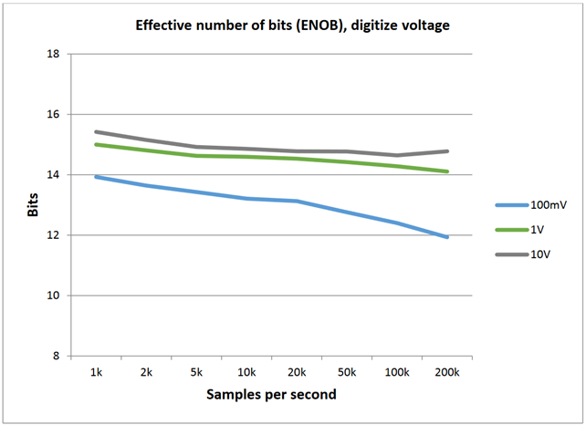
DC-COUPLED EFFECTIVE NUMBER OF BITS (ENOB), TYPICAL70
69 Specified with aperture Auto, 100 Hz sine wave for sample rate ≤ 5 k, and 1 kHz sine wave for sample rate ≥ 10 k. Distortion is calculated using first five harmonics.
70 Specified with aperture Auto, 100 Hz sine wave for sample rate ≤5 k, and 1 kHz sine wave for sample rate ≥10 k. For the 100 V and 1000 V ranges, use the 1 V and 10 V range ENOB, respectively; guaranteed by design.
DIGITIZE CURRENT
DC ACCURACY71
| Range72 | Resolution73 | Burden Voltage | Accuracy ± ± [ppm of reading + ppm of range] | |||
| 90 day TCAL ±5 °C |
1 year TCAL ± 5 °C |
2 year TCAL ± 5 °C |
Temperature coefficient74 | |||
| 10 µA | 0.1 nA | 15 mV | 150 + 75 | 160 + 75 | 170 + 75 | 30 + 15 |
| 100 µA | 1 nA | 15 mV | 150 + 75 | 160 + 75 | 170 + 75 | 30 + 15 |
| 1 mA | 10 nA | 15 mV | 150 + 75 | 160 + 75 | 170 + 75 | 30 + 15 |
| 10 mA | 100 nA | 20 mV | 150 + 75 | 160 + 75 | 170 + 75 | 30 + 15 |
| 100 mA | 1 µA | 200 mV | 340 + 100 | 450 + 100 | 560 + 100 | 50 + 20 |
| 1 A | 10 µA | 400 mV | 400 + 110 | 500 + 110 | 600 + 110 | 50 + 25 |
| 3 A | 100 µA | 1300 mV | 650 + 150 | 900 + 150 | 900 + 150 | 50 + 25 |
| 10 A75 | 100 µA | 650 mV | 950 + 350 | 1500 + 350 | 2000 + 350 | 50 + 25 |
SIGNAL CHARACTERISTICS, TYPICAL76
| Range72 | Maximum flatness error 3 Hz to 20 kHz |
Analog bandwidth (−3 dB) |
Total harmonic distortion (THD) 20 kHz signal (−1 dB FS) |
Settling time, dc-coupled (0.5%) |
| 10 µA | 0.15 dB | 100 kHz | 0.02% | 8 µs |
| 100 µA | 0.15 dB | 100 kHz | 0.01% | 7 µs |
| 1 mA | 0.1 dB | 100 kHz | 0.01% | 3 µs |
| 10 mA | 0.1 dB | 100 kHz | 0.01% | 8 µs |
| 100 mA | 0.1 dB | 100 kHz | 0.02% | 5 µs |
| 1 A77 | 0.1 dB | 100 kHz | 0.02% | 6 µs |
| 3 A77 | 0.1 dB | 100 kHz | 0.02% | 6 µs |
| 10 A75, 77, 78 | 0.1 dB | 100 kHz | 0.02% | 6 µs |
71 Accuracy with sample rate 1 k per second, aperture auto, and 100 reading buffer average.
72 20% overrange on all ranges except 3.3% for 3 A and 10 A ranges.
73 Power up default is 4½ digits.
74 Add per degree from TCAL ±5 °C.
75 Rear input terminals only.
76 Verified with sine wave input and dc content ≤ 3% of range. For flatness error, 0 dB reference frequency is 3 Hz.
77 For the 1 A, 3 A, and 10 A ranges, use the 100 mA range accuracy; guaranteed by design.
78 10 A flatness verified to 10 kHz; 100 kHz guaranteed by design.
ADDITIONAL NOISE UNCERTAINTY, TYPICAL79

TOTAL HARMONIC DISTORTION (THD), TYPICAL80

79 Specified with aperture Auto and open input terminals. For all ranges and for ≥1 k sample rate, add an additional 3 × RMS noise uncertainty to ppm of range.
80 Specified with aperture Auto, 100 Hz sine wave for sample rate ≤ 5 k, and 1 kHz sine wave for sample rate ≥ 10 k. Distortion is calculated using first five harmonics. For the 1 A, 3 A, and 10 A ranges, use the 100 mA range accuracy; guaranteed by design.
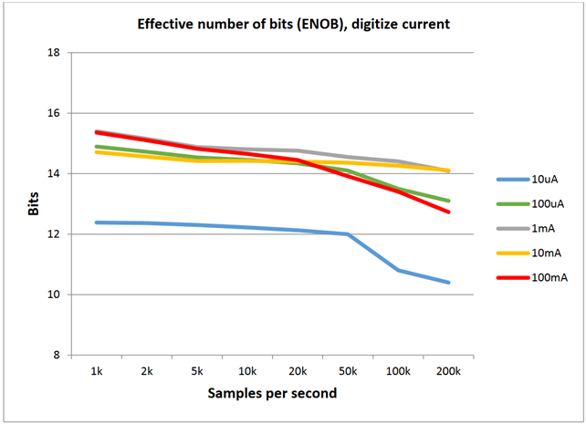
EFFECTIVE NUMBER OF BITS (ENOB), TYPICAL81
DIGITIZER CHARACTERISTICS
| Maximum resolution | 18 bits |
| Measurement input coupling | Voltage only, dc or ac |
| Sampling rate82 | Programmable 1 k through 1 M samples per second |
| Volatile sample memory with timestamp | 27.5 million |
| Minimum sampling time | 1 µs |
| Timestamp resolution | 1 ns with standard or full buffer style 1 µs with compact buffer style |
| Timestamp accuracy | With standard or full buffer style, 20 ns between adjacent readings,
with total buffer time < 2 s With compact buffer style, 2 µs adjacent readings, with total buffer time < 2 s |
| Maximum sample memory | 8 million |
81 Specified with aperture Auto, 100 Hz sine wave for sample rate ≤5 k, and 1 kHz sine wave for sample rate ≥10 k. For the 1 A, 3 A, and 10 A ranges, use the 100 mA ENOB; guaranteed by design.
82 Sample rate is not continuously adjustable. For valid discrete settings, see the Model DMM7510 Reference Manual.
TRUE RMS AC VOLTAGE AND AC CURRENT
| Function | Range83 | Resolution | 1 year accuracy: ± (% of reading + % of range) TCAL ± 5 °C | |||||
| 3 Hz to 5 Hz |
5 Hz to 10 Hz |
10 Hz to 20 kHz |
20 kHz to 50 kHz |
50 kHz to 100 kHz |
100 kHz to 300 kHz |
|||
| Voltage84 | 100 mV | 0.1 µV | 1.0 + 0.03 | 0.30 + 0.03 | 0.06 + 0.03 | 0.14 + 0.05 | 0.6 + 0.08 | 4.0 + 0.5 |
| 1 V | 1 µV | 1.0 + 0.03 | 0.30 + 0.03 | 0.06 + 0.03 | 0.14 + 0.05 | 0.6 + 0.08 | 4.0 + 0.5 | |
| 10 V | 10 µV | 1.0 + 0.03 | 0.30 + 0.03 | 0.06 + 0.03 | 0.14 + 0.05 | 0.6 + 0.08 | 4.0 + 0.5 | |
| 100 V | 100 µV | 1.0 + 0.03 | 0.30 + 0.03 | 0.06 + 0.03 | 0.14 + 0.05 | 0.6 + 0.08 | 4.0 + 0.5 | |
| 700 V | 1 mV | 1.0 + 0.03 | 0.30 + 0.03 | 0.06 + 0.03 | 0.14 + 0.05 | 0.6 + 0.08 | 4.0 + 0.5 | |
| Temperature coefficient / °C (all ranges)85 |
— | — | 0.01 + 0.003 | 0.03 + 0.003 | 0.05 + 0.003 | 0.006 + 0.005 | 0.01 + 0.006 | 0.03 + 0.01 |
| Function | Range83 | Resolution | 1 year accuracy: ± (% of reading + % of range) TCAL ± 5 °C | ||||
| 3 Hz to 5 Hz | 5 Hz to 10 Hz | 10 Hz to 2 kHz | 2 kHz to 5 kHz | 5 kHz to 10 kHz | |||
| Current84 | 1 mA | 1 nA | 1.0 + 0.04 | 0.30 + 0.04 | 0.08 + 0.03 | 0.09 + 0.03 | 0.09 + 0.03 |
| 10 mA | 10 nA | 1.0 + 0.04 | 0.30 + 0.04 | 0.08 + 0.03 | 0.09 + 0.03 | 0.09 + 0.03 | |
| 100 mA | 100 nA | 1.0 + 0.04 | 0.30 + 0.04 | 0.08 + 0.03 | 0.09 + 0.03 | 0.09 + 0.03 | |
| 1 A | 1 µA | 1.0 + 0.04 | 0.30 + 0.04 | 0.20 + 0.04 | 0.88 + 0.04 | 2.0 + 0.04 | |
| 3 A | 1 µA | 1.0 + 0.05 | 0.30 + 0.05 | 0.20 + 0.05 | 0.88 + 0.05 | 2.0 + 0.05 | |
| 10 A85 | 10 µA | 1.0 + 0.05 | 0.40 + 0.05 | 0.40 + 0.05 | 0.88 + 0.05 | 2.0 + 0.05 | |
| Temperature coefficient / °C (all ranges)85 |
‐ | ‐ | 0.10 + 0.004 | 0.030 + 0.004 | 0.005 + 0.003 | 0.006 + 0.005 | 0.006 + 0.005 |
ADDITIONAL AC UNCERTAINTIES – LOW FREQUENCY UNCERTAINTY
| Additional uncertainty ±(% of reading), lower frequency uncertainty |
Detector bandwidth (BW) | ||
| 3 BW (3 Hz to 300 kHz) | 30 BW (30 Hz to 300 kHz) | 300 BW (300 Hz to 300 kHz) | |
| 20 Hz to 30 Hz | 0 | 0.3 | — |
| 30 Hz to 50 Hz | 0 | 0 | — |
| 50 Hz to 100 Hz | 0 | 0 | 4.0 |
| 100 Hz to 200 Hz | 0 | 0 | 0.72 |
| 200 Hz to 300 Hz | 0 | 0 | 0.18 |
| 300 Hz to 500 Hz | 0 | 0 | 0.07 |
| > 500 Hz | 0 | 0 | 0 |
83 20% overrange on ac functions except 1% on 700 V, 3.33% on 3 A and 1% on 10 A. Default resolution is 6½ digits.
84 Specifications are for detector bandwidth of 3 Hz and sine wave inputs > 5% of range. Detector bandwidth of 3 Hz and 30 Hz are multisample A/D conversions. Detector bandwidth of 300 Hz is a single A/D conversion, programmable from 0.0005 PLC to 15 PLC (60 Hz), 12 PLC (50 Hz). Default condition set to 1 PLC.
85 Add per degree from TCAL ±5 °C; specifications without autocalibration.
86 Rear input terminals only.
ADDITIONAL AC VOLTAGE CREST FACTOR UNCERTAINTIES87
Additional uncertainty ± (% of reading)
| Input signal frequency | Detector bandwidth | Crest factor Maximum crest factor: 5 at range full scale |
|||
| 1 to 2 | 2 to 3 | 3 to 4 | 4 to 5 | ||
| 3 Hz to 5 Hz | 3 Hz | 1.00 | 4.00 | 4.80 | 5.00 |
| 5 Hz to 10 Hz | 3 Hz | 0.50 | 1.20 | 1.30 | 1.40 |
| 10 Hz to 30 Hz | 3 Hz | 0.20 | 0.30 | 0.60 | 0.90 |
| 5 Hz to 100 Hz | 30 Hz | 0.20 | 0.30 | 0.60 | 0.90 |
| 100 Hz to 300 Hz | 30 Hz | 0.05 | 0.15 | 0.30 | 0.40 |
| 100 Hz to 300 Hz | 300 Hz | 0.50 | 1.20 | 1.30 | 1.50 |
| 500 Hz to 10 kHz | 300 Hz | 0.05 | 0.15 | 0.30 | 1.20 |
AC VOLTAGE CHARACTERISTICS
| Measurement method | Uses ac-coupled true RMS |
| Input impedance | 1 MΩ ± 2% ǁ < 150 pF |
| Volt*Hertz product | < 2.1 x 10⁷ V*Hz verified; input frequency verified for < 300 kHz |
AC CURRENT CHARACTERISTICS
| Measurement method | Uses ac-coupled true RMS |
| Range | 1 mA | 10 mA | 100 mA | 1 A | 3 A | 10 A88 |
| Burden voltage (RMS) | < 16 mV | < 20 mV | < 0.2 V | < 0.4 V | < 1.3 V | < 0.65 V |
| Overload recovery: For each additional sustained ampere beyond ±1.5 A, add the following initial % of range error until thermally settled after overload recovery |
0.006 | 0.006 | 0.12 | 0.05 | — | — |
87 Applies for non-sine wave inputs, DC content ≤ 3% of range, maximum crest factor ≤ 5.0.
88 Rear input terminals only.
FREQUENCY AND PERIOD
MEASUREMENT ACCURACY89
| Aperture | Measurement resolution | Accuracy ±[ppm of reading + ppm of aperture time] Frequency: 3 Hz to 500 kHz Period: 333 ms to 2 µs |
|
| 1 year TCAL ±5 °C |
1 year TCAL ±5 °C |
||
| 250 ms | 0.1 ppm | 80 + 0.333 | 160 + 0.333 |
| 100 ms | 0.1 ppm | 80 + 3.33 | 160 + 3.33 |
| 10 ms | 0.1 ppm | 80 + 33.3 | 160 + 33.3 |
THRESHOLD LEVEL ACCURACY90
| Threshold range | Threshold resolution | Accuracy ±[% of range] |
| 2 year TCAL ±5 °C |
||
| 100 mV to 700 V | 0.05% | 1.0% |
FREQUENCY AND PERIOD CHARACTERISTICS
| Measurement method | Reciprocal counting technique |
| Aperture | 10 ms to 273 ms; default is 10 ms |
89 Specified for square wave inputs. Input signal must be >10% of ACV range. If input is <20 mV on the 100 mV range, then the frequency must be >10 Hz. For sine wave inputs, frequency must be >100 Hz. For frequencies ≤100 Hz, threshold level ≤50% of input signal and ≤7 Hz, threshold level ≤3% of range.
90 Threshold range is voltage RMS and threshold level voltage peak. Specified with 1 KHz square wave. 100 V and 700 V threshold ranges guaranteed by design.
TYPICAL READING RATES, 60 Hz (50 Hz) OPERATION91, 92, 93, 94
| Functions: dc voltage (10 V) 2-wire ohms (≤ 10 kΩ) dc current (1 mA) |
Functions: 4-wire ohms (≤ 1 kΩ) 4-wire / 3-wire RTD |
Functions: Thermistor |
Functions: Dry circuit (≤ 1 kΩ) |
||||||
| NPLC | Digits | Measurements into buffer | Measurements into computer | Measurements into buffer | Measurements into computer | Measurements into buffer | Measurements into computer | Measurements into buffer | Measurements into computer |
| 1 | 7½ | 59.8 (49.8) | 58 (48) | 29 (24) | 28 (24) | 57 (48) | 57 (48) | 27 (23) | 26 (22) |
| 0.2 | 6½ | 295 (240) | 250 (210) | 128 (109) | 119 (100) | 230 (200) | 230 (200) | 100 (89) | 96 (85) |
| 0.06 | 5½ | 965 (810) | 950 (800) | 310 (280) | 315 (280) | 900 (750) | 900 (750) | 190 (180) | 190 (180) |
| 0.006 | 4½ | 7500 (6700) | 7300 (6500) | 750 (730) | 740 (720) | 6800 (6000) | 6800 (6000) | 295 (290) | 295 (290) |
| 0.0005 | 3½ | 26000 (26000) | 24000 (24000) | 860 (860) | 860 (860) | 18000 (18000) | 18000 (18000) | 310 (310) | 310 (310) |
| Functions: ac voltage, ac current |
|||
| Detector bandwidth (Hz) | Digits | Measurements into buffer | Measurements into computer |
| 3 | 6½ | 0.5 (0.5) | 0.5 (0.5) |
| 30 | 6½ | 3.3 (3.3) | 3.3 (3.3) |
| 30095 | 6½ | 59.8 (49.8) | 55 (46) |
| 30095 | 3½ | 26200 (26200) | 24500 (24500) |
DIGITIZE, TYPICAL
| Sampling rates (samples per second) |
Digits | Resolution | Measurements into computer94 |
| 10,000 | 5½ | 18 | Up to 9,700 readings per second |
| 20,000 | 4½ | 16 | Up to 19,000 readings per second |
| 50,000 | 4½ | 16 | Up to 44,400 readings per second |
| 100,000 | 4½ | 15 | Up to 80,000 readings per second |
| 1,000,000 up to eight second maximum duration | 3½ | 12 | At least 108,000 readings per second |
91 Reading speeds for autozero off, fixed range, autodelay off. Offset compensation off and open lead detector off where applicable.
92 Buffer measurements: For < 0.2 PLC, multisample, single buffer transfer binary reading only.
93 PC measurements: For 1 and 0.2 PLC single reading and single transfer to computer (USB).
94 Reading rates using factory default operating conditions and autorange off, autodelay off. Speeds include measurement and data transfer out of the USB. ≥1000 readings with 4-byte binary transfer over USB.
95 For bandwidth 300 Hz, autozero off, 6½ digits at 1 PLC, 3½ digits at 0.0005 PLC.
SYSTEM PERFORMANCE, TYPICAL
- Mode: 3½ digit, autozero off, autorange off, threshold autorange off, 0.0005 PLC, excludes measurement time
- Time includes function change from DC voltage or 2-wire ohms to listed function
| Function | Function change (ms) | Range change (ms) |
| DC voltage or 2-wire ohms (< 10 kΩ) | 6 | 1.3 |
| 4-wire ohms (< 10 kΩ) | 7 | 1.3 |
| DC current | 7 | 1.3 |
| Frequency or period96 | 7 | 1.3 |
| AC voltage or ac current | 7 | 1.3 |
| Digitize voltage or current | 7 | 1.3 |
96 For dc voltage or 2-wire ohms to frequency or period, 10 ms aperture. For ac current or ac voltage, detector bandwidth is 300 Hz.
RANGES FOR FUNCTION CHANGE TIMES
Function change times apply to the ranges listed in the table below.
| Function | Range |
| DC voltage | 10 V |
| 2-wire or 4-wire ohms | 1 kΩ |
| DC current | 1 mA |
| Dry-circuit ohms | 10 Ω |
| Thermocouple | Use dc voltage rates |
| Thermistor | Use 2-wire ohms rates |
| AC current | 1 mA |
| AC voltage | 1 V |
| Buffer transfer speed (binary) | Measurements into computer (per second) | ||
| USB | LAN | GPIB | |
| Average for 1000 readings | 280000 | 270000 | 190000 |
| Average for 1000 readings with timestamp | 170000 | 140000 | 100000 |
TRIGGERING
| Time base accuracy | 25 ppm |
| Trigger source | Analog dc voltage, dc current, or any system trigger |
| Trigger coupling | DC or ac (dc voltage function only) |
| Input trigger latency97, 98, 99 | < 225 ns |
| Input trigger jitter97, 98 | < 50 ns |
| Sample period jitter97, 98 | < 1 ns |
DMM REAR-PANEL TRIGGERS
| EXT TRIG IN and OUT | 0 V to 5 V logic signal input and output, TTL-compatible |
| EXT trigger latency (IN and OUT) | < 400 ns |
| EXT trigger latency (IN or OUT) | < 200 ns (guaranteed by design) |
ANALOG TRIGGERING100
ANALOG LEVEL, EDGE, OR WINDOW TRIGGER TYPES101
| Trigger characteristics | Voltage input | Current input |
| Input range | 100 mV to 1000 V | 10 µA to 10 A |
| Resolution | 0.05% | 0.05% |
| Basic accuracy (TACAL ±5 °C)102, 103 | ±1% | ±1% |
ANALOG TRIGGER LATENCIES
| Digital I/O | External | |
| Positive logic | 800 ns + 40 ns jitter | 930 ns + 40 ns jitter |
| Negative logic | 800 ns + 40 ns jitter | 840 ns + 40 ns jitter |
WINDOW FILTER AND MEMORY (BUFFER)
| Window filter size | 0 to 10% of reading, where 0 averages all readings |
| Memory | Up to 27.5 million timestamped readings with the compact buffer style, with additional memory available using an external USB flash drive |
| Maximum internal memory (buffer) | 27.5 million readings with the compact buffer style (6½-digit without formatting); 11 million readings with the standard or full buffer styles |
97 Guaranteed by design; for digital I/O only.
98 Stimulus command required to meet specifications.
99 If using trigger model, add 200 ns uncertainty.
100 For dc or ac coupled, the trigger level can be set up to 100% of measure range.
101 Rising or falling edge triggering supported. Window trigger requires setting two independent levels.
102 Trigger event occurs after the threshold crossing at a time determined by total trigger latencies.
103 Accuracy specifications require user ACAL and are verified with level trigger amplitude set to 50% of range with a 100 Hz sine wave at 100% full scale of range. High frequency rejection is off. NPLC 0.0005 (dc voltage/dc current) or aperture 1 µs for digitize voltage or digitize current. Specified for fixed range, autozero off. For digitized dc voltage ac coupled, add 0.5%. For dc current and digitized dc current 3 A or 10 A ranges, add an additional 2%.
GENERAL INSTRUMENT SPECIFICATIONS
SPECIFICATION CONDITIONS
This document contains specifications and supplemental information for the DMM7510 Precision Sampling Digital Multimeter instrument. Specifications are the standards against which the DMM7510 is tested. Upon leaving the factory, the DMM7510 meets these specifications. Supplemental, typical, and characteristic values are non-warranted, apply at 23 °C, and are provided solely as useful information. All specifications apply to front or rear terminal inputs, except 10 A specifications (rear-terminals only).
| Input protection | 1010 V dc (715 VRMS V ac) all ranges and functions on HI and LO terminals; 350 V all ranges and functions on sense HI, sense LO terminals; 250 V rated current input terminal; fused 3 A and 10 A ranges; current input terminals protected to 1 kV | |
| 3 A input fuse protection | 3.5 A, 1 kV fast blow type; Keithley part number DMM7510-FUSE-3A | |
| 10 A input fuse protection | 11 A, 1 kV fast blow type; Keithley part number DMM7510-FUSE-10A | |
| AC voltage input | Maximum dc voltage: 1000 V on any AC voltage range | |
| Common mode isolation | 500 V dc or ac Vpeak LO to chassis All terminals > 10 GΩ, < 350 pF any terminal to chassis | |
| Power line | Universal input, 100 V to 240 V | |
| Line frequency | 50 Hz or 60 Hz, automatically sensed at power-up | |
| Power consumption | 60 VA maximum | |
| Operating environment | Specified for 0 °C to 50 °C, ≤ 80% relative humidity at 35 °C, altitude up to 2000 meters | |
| Storage environment | -30 °C to 70 °C | |
| Real time clock | Lithium battery backup (3+ years battery life) | |
| EMC | Conforms to European Union EMC Directive | |
| Safety | NRTL listed to UL61010-1, and CSA C22.2 No 61010-1; conforms with European Union Low Voltage Directive | |
| Vibration | MIL-PRF-28800F Class 3, Random | |
| Warm-up | 90 minutes to rated accuracy | |
| Input signal connections | Front and rear safety banana jacks | |
| Cooling | Forced air, fixed speed | |
| Dimensions | Without handle and bumpers: 88 mm high × 213 mm wide ×
410 mm deep (3.46 in. × 8.39 in. × 16.13 in.) With handle and bumpers (bench configuration): 106 mm high × 255 mm wide × 425 mm deep (4.18 in. × 10.05 in. × 16.75 in.) |
|
| Shipping weight (with bumpers and handle) | 4.08 kg (9.0 lb) | |
| Shipping weight (without bumpers and handle) | 3.63 kg (8.0 lb) | |
| Digital I/O | Connector | 9-pin female D |
| 5 V power supply pin | Limited to 500 mA at > 4 V (solid-state fuse protected) | |
| Lines | Six input/output, user-defined, for digital I/O or triggering | |
| Input signal levels | 0.7 V (maximum logic low) 3.7 V (minimum logic high) |
|
| Input voltage limits | -0.25 V (absolute minimum) +5.25 V (absolute maximum) |
|
| Maximum source current | +2.0 mA at > 2.7 V (per pin) | |
| Maximum sink current | 50 mA at 0.7 V (per pin, solid-state fuse protected) | |
|
Handler |
User-defined start of test, end of test, four category bits | |
| Math functions | Rel, dB, Limit Test, Percentage, 1/x, and mX + b | |
| Remote interface |
LAN: RJ-45 connector, 10/100BT; Virtual Front Panel GPIB: IEEE-488.1 compliant. Supports IEEE-488.2 common commands and status model topology USB device (rear panel, type B): 2.0 full speed, USBTMC compliant USB host (front panel, type A): USB 2.0, support for flash drives, FAT 32 |
|
| LXI compliance | 1.5 LXI Device Specification 2016 | |
| Language | Embedded Test Script Processor (TSP) accessible from any host interface; responds to high-speed test scripts comprised of remote commands and statements (for example, branching, looping, math); able to execute high-speed test scripts stored in memory without host intervention; also SCPI (default command set) | |
| Display | Five-inch capacitive touch, color thin-film-transistor (TFT) WVGA (800 x 480) with LED backlight | |
| Password protection | 30 characters | |
| Expansion interface | The TSP-Link® expansion interface allows TSP-enabled instruments to trigger and communicate with each other | |
| IP configuration | Static or DHCP (manual or automatic) | |
Find more valuable resources at TEK.COM
Copyright © Tektronix. All rights reserved. Tektronix products are covered by U.S. and foreign patents, issued and pending. Information in this publication supersedes that in all previously published material. Specification and price change privileges reserved. TEKTRONIX and TEK are registered trademarks of Tektronix, Inc. All other trade names referenced are the service marks, trademarks or registered trademarks of their respective companies.
SPEC-DMM7510 Rev. B/October 2016