

Contact us
Live Chat with Tek representatives. Available 6:00 AM - 4:30 PM
Call us at
Available 6:00 AM – 5:00 PM (PST) Business Days
Download
Download Manuals, Datasheets, Software and more:
Feedback
Power Measurement Deskew & Calibration Fixture Instructions
This document is targeted to product users and explains operation and/or installation procedures.
This manual applies to:
TAP1500, TAP2500 0, TAP3500 0, TDP0500, TDP1000, TDP1500 0, P6243, P6245, P6247, P6248, P6251, TCP0150, TCP303, A6312, A6303, TAP4000, P5050B 0, TPP0250, TPP0500 0, TPP1000 0, TDP3500 0, TDP4000, P5200A, P5205A 0, P5210A 0, THDP0200, TMDP0200, THDP0100, TCP0030A, TCP0020, TCP2020, TCP202A, TCP312A, TCP305A
Related Product Information
Bằng cách tải xuống, bạn đồng ý với các điều khoản và điều kiện của Thỏa thuận Tải xuống Hướng dẫn sử dụng.
Thỏa thuận Tải xuống Tài liệu Hướng dẫn
CHÚ Ý: vui lòng đọc kỹ các điều khoản và điều kiện sau trước khi tải xuống bất kỳ tài liệu nào từ trang web này. Bằng cách tải xuống hướng dẫn sử dụng từ trang web của Tektronix, bạn đồng ý với các điều khoản và điều kiện sau:
Hướng dẫn sử dụng cho các sản phẩm hiện đang được hỗ trợ:
Tektronix theo đây cấp phép và quyền cho chủ sở hữu các thiết bị Tektronix được tải xuống và sao chép các tài liệu hướng dẫn trên trang web này cho mục đích sử dụng nội bộ hoặc cá nhân của riêng họ. Tài liệu hướng dẫn cho các sản phẩm hiện đang được hỗ trợ không được sao chép để phân phối cho người khác trừ khi được Tektronix, Inc. cấp phép bằng văn bản cụ thể.
Hướng dẫn sử dụng của Tektronix có thể đã được sửa đổi để phản ánh các thay đổi được thực hiện đối với sản phẩm trong vòng đời sản xuất của sản phẩm đó. Do đó, các phiên bản hướng dẫn sử dụng khác nhau có thể tồn tại đối với bất kỳ sản phẩm cụ thể nào. Cần cẩn thận để đảm bảo rằng người dùng có được phiên bản hướng dẫn sử dụng phù hợp cho số sê-ri sản phẩm cụ thể.
Tài liệu hướng dẫn cho các sản phẩm không còn được hỗ trợ:
Tektronix không thể cung cấp tài liệu hướng dẫn cho các sản phẩm đo lường không còn đủ điều kiện hỗ trợ lâu dài. Tektronix theo đây cấp phép và quyền cho người khác sao chép và phân phối các bản sao của bất kỳ tài liệu hướng dẫn sản phẩm đo lường nào của Tektronix, bao gồm tài liệu hướng dẫn sử dụng, tài liệu hướng dẫn vận hành, tài liệu hướng dẫn dịch vụ và tương tự, mà (a) có Số bộ phận của Tektronix và (b) dành cho sản phẩm đo lường không còn được Tektronix hỗ trợ.
Tài liệu hướng dẫn của Tektronix có thể được sửa đổi để phản ánh các thay đổi được thực hiện đối với sản phẩm trong vòng đời sản xuất. Do đó, các phiên bản tài liệu hướng dẫn khác nhau có thể tồn tại cho bất kỳ sản phẩm cụ thể nào. Cần thận trọng để đảm bảo rằng người dùng có được phiên bản tài liệu hướng dẫn phù hợp cho số sê-ri sản phẩm cụ thể.
Giấy phép và quyền này không áp dụng cho bất kỳ tài liệu hướng dẫn hoặc ấn phẩm nào khác vẫn có sẵn từ Tektronix, hoặc cho bất kỳ tài liệu hướng dẫn hoặc ấn phẩm nào khác dành cho sản phẩm sản xuất video hoặc sản phẩm máy in màu.
Tuyên bố miễn trừ trách nhiệm:
Tektronix không đảm bảo tính chính xác hoặc đầy đủ của thông tin, văn bản, đồ họa, sơ đồ mạch, danh sách bộ phận hoặc tài liệu khác có trong bất kỳ hướng dẫn sử dụng sản phẩm đo lường nào hoặc ấn phẩm khác không do Tektronix cung cấp hoặc được sản xuất hoặc phân phối theo sự cho phép và giấy phép nêu trên.
Tektronix có thể thay đổi nội dung của trang web này hoặc các sản phẩm của mình bất cứ lúc nào mà không cần thông báo.
Giới hạn Trách nhiệm pháp lý:
TEKTRONIX SẼ KHÔNG CHỊU TRÁCH NHÁCH VỀ BẤT KỲ TỆN HẠI NÀO (BAO GỒM, KHÔNG GIỚI HẠN, BẤT KỲ TỆN HẠI DO HẬU QUẢ HOẶC NGẪU NHIÊN, TỆN HẠI DO MẤT LỢI NHUẬN, GIÁN ĐOẠN KINH DOANH, HOẶC DO VI PHẠM QUYỀN SỞ HỮU TRÍ TUỆ) PHÁT SINH TỪ VIỆC SỬ DỤNG BẤT KỲ TÀI LIỆU HƯỚNG DẪN SẢN PHẨM ĐO LƯỜNG HOẶC ANH PHẨM NÀO KHÁC DO TEKTRONIX SẢN XUẤT HOẶC PHÂN PHỐI THEO GIẤY PHÉP VÀ QUYỀN NÊU TRÊN.
Read Online
Overview
This fixture converts the oscilloscope PROBE COMPENSATION output (Probe Calibration on DPO7000C Series) or the TEK-DPG pulse generator output into a set of test point connections. These connections provide you with a convenient way to compensate for timing differences between voltage and current probes.
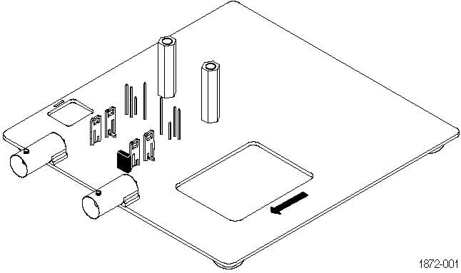
You can also optimize the instrument gain and offset accuracy at the probe tips for both voltage and current probes. Use the table as a guide to connect a variety of Tektronix voltage and current probes together on the fixture.
Connecting to the instrument
The fixture has two BNC inputs, Port A and Port B. The jaw size of the current probes and the operation that you want to perform determine which input to use. Use the included BNC cable to connect the fixture input to the Probe Calibration output of your DPO7000C instrument or to an external generator. Other TekVPI oscilloscope models, including the MDO3000 and MDO4000C series, 3 Series MDO and 4/5/6 Series B MSO, require the TEK-DPG pulse generator or an external generator as the signal source.
 | CAUTION:The maximum allowable voltage applied to either input is 8 V RMS. Voltages in excess of 8 V RMS can damage the fixture. |
Passive voltage probes fixture input guide
The following table supports P6139B, P5050B, TPP0250 TPP0500B, TPP1000, and other 10X passive probes. Not all probes are usable with all instruments. Gain and offset calibration is generally not needed for these probes.
| Operation | Input |
|---|---|
| Low frequency compensation | B |
| Gain and offset calibration (remove jumper from fixture to perform this operation) | B |
| Compensate timing with respect to current probes | A/B (use Port A for small current probes, Port B for large) |
Active voltage probes fixture input guide
The following table supports TAP1500, TAP2500, TAP3500, TAP4000, TDP0500, TDP1000, TDP1500, TDP3500, TDP4000, P6243, P6245, P6247, P6248, and P6251 probes. Not all probes are usable with all instruments.
| Operation | Input |
|---|---|
| Gain and offset calibration (remove jumper from fixture to perform this operation) | B |
| Compensate timing with respect to current probes | A/B (use Port A for small current probes, Port B for large) |
High voltage probes fixture input guide
The following table supports P5200A, P5205A, P5210A (requires external signal source), THDP0200, TMDP0200, and THDP0100 probes. Not all probes are usable with all instruments.
| Operation | Input |
|---|---|
| Gain and offset calibration (remove jumper from fixture to perform this operation) | B |
| Compensate timing with respect to current probes | A/B (use Port A for small current probes, Port B for large) |
Current probes fixture input A guide
The following table supports TCP0030A, TCP0020, TCP2020, TCP202A, TCP312A, and TCP305A probes. Not all probes are usable with all instruments.
| Operation | Input |
|---|---|
| Gain and offset calibration | A |
| Compensate timing with respect to current probes | A |
Current probes fixture input B guide
The following table supports TCP303 and TCP0150 probes. Not all probes are usable with all instruments.
| Operation | Input |
|---|---|
| Gain and offset calibration | B |
| Compensate timing with respect to current probes | B |
Connecting probes
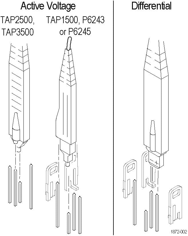
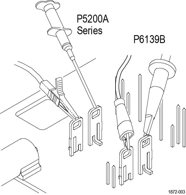
The following diagrams show how to attach each type of probe tip to the fixture. Refer to the ground symbols on the fixture to establish the correct polarity.
| WARNING:To avoid personal injury, use care while connecting probe tips to the square pins on the fixture. The ends of the square pins are sharp. |
Active Voltage or Differential probes
For Active Voltage probes (TAP1500, TAP2500, TAP3500, TAP4000, P6243, or P6245), connect the probe tip to the short pin and the probe ground to the long pin as shown.
For Differential probes (TDP0500, TDP4000, TDP3500, TDP1000, TDP1500, P6247, P6248, or P6251), connect the probe + input to the signal pin and the probe – input to the ground pin as shown. There is no connection to the probe ground input.
Passive Voltage or High Voltage probes
For P6139B or P5200 Series probes, connect the probe tip and the ground lead to the two terminals as shown.
Current probes
For TCP0030A, TCP0020, TCP2020, TCP202A, TCP312A, TCP305A, TCP0150, and TCP303 probes, connect the current probe around the current loop as shown. Be sure to align the polarity arrows on the current probe and the fixture, and make sure the current probe slider is closed and locked.

Using the fixture
Perform the following steps to use the fixture. For best results, warm up the equipment for 20 minutes before performing these functions.
Optimize Gain and Offset Accuracy
Not all oscilloscopes support this function.
- Connect the Port A or Port B side of the fixture to the instrument, depending on the probe type. If you are optimizing the gain and offset accuracy for a voltage probe on Port B, remember to remove the small jumper over the two pins on the fixture.
- Connect the probe to the fixture as described in Connecting Probes.
- Initiate the Calibrate Probe routine.
- When the routine is finished, remove the connections and replace the small jumper across the two pins on the fixture. Leave the jumper installed for all other functions.
Compensate probe timing (Deskew)
- Connect the Port A or Port B side of the fixture to the instrument, depending on the probe type.
- Connect the probes to the fixture.
- Display all channels that you want to deskew.
- Push the AUTOSET button on the instrument front panel.
- Adjust vertical SCALE and POSITION for each channel so that the signals overlap and are centered on-screen (with active probes, adjusting offset may be required).
- Adjust horizontal POSITION so that a triggered rising edge is at center screen.
- Adjust horizontal SCALE so that the differences in the channel delays are clearly visible.
- Adjust horizontal POSITION again so that the first rising edge is exactly at center screen. The fastest probe is connected to this channel. The fastest probe is probably the one with the shortest cable or the highest bandwidth.
- Touch the VERT button or use the Vertical menu to display the vertical control window.
- Touch the Probe Deskew button to display the channel-deskew control window.
- Select one of the slower channels. If possible, perform the next step at a signal amplitude within the same attenuator range (vertical scale) as your planned signal measurements. Any change to the vertical scale after deskew is complete may introduce a new attenuation level (you can generally hear attenuator settings change) and therefore a slightly different signal path. This different path may cause up to a 200 ps variation in timing accuracy between channels.
- Adjust the deskew time for that channel so that the signal aligns with that of the fastest channel.
- Repeat steps 11 and 12 for each additional channel that you want to deskew.
- Remove the connections.
Schematics
The schematic diagrams that follow show typical connections for both small and large style current probes.
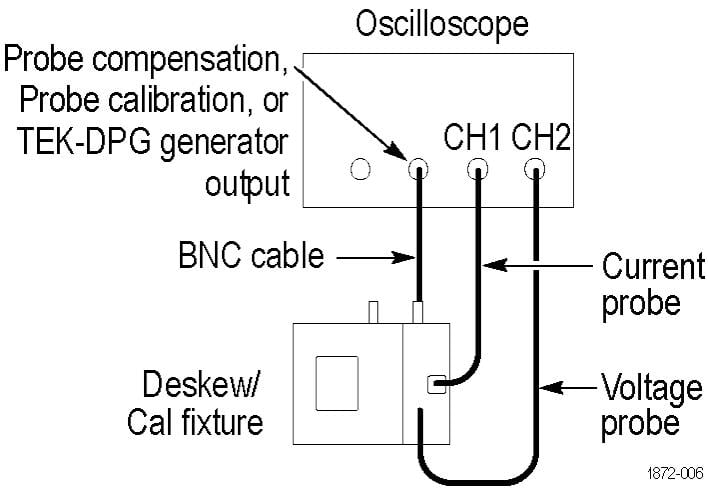
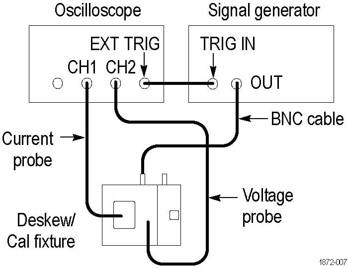
| CAUTION:The maximum allowable voltage applied to either fixture input (Port A or Port B) is 8 V RMS. Voltages in excess of 8 V RMS may damage the fixture. |
Safety summary
To avoid potential hazards, use this product only as specified.
To avoid fire or personal injury, do not operate in wet/damp conditions.
Keep product surfaces clean and dry.
Refer to your probe manual for additional safety information.
Terms in this manual and on the product
These terms may appear in this manual:
| WARNING:Warning statements identify conditions or practices that could result in injury or loss of life. |
| CAUTION:Caution statements identify conditions or practices that could result in damage to this product or other property. |
These terms may appear on the product:
- DANGER indicates an injury hazard immediately accessible as you read the marking.
- WARNING indicates an injury hazard not immediately accessible as you read the marking.
- CAUTION indicates a hazard to property including the product.