

與我們聯絡
與 Tek 業務代表即時對談。 上班時間:上午 6:00 - 下午 4:30 (太平洋時間)
請致電
與 Tek 業務代表即時對談。 上班時間:上午 8:30 - 下午 5:30 (太平洋時間)
下載
下載手冊、產品規格表、軟體等等:
意見回饋
Power Measurement Deskew & Calibration Fixture Instructions
This document is targeted to product users and explains operation and/or installation procedures.
此手冊適用於:
TAP1500, TAP2500 0, TAP3500 0, TDP0500, TDP1000, TDP1500 0, P6243, P6245, P6247, P6248, P6251, TCP0150, TCP303, A6312, A6303, TAP4000, P5050B 0, TPP0250, TPP0500 0, TPP1000 0, TDP3500 0, TDP4000, P5200A, P5205A 0, P5210A 0, THDP0200, TMDP0200, THDP0100, TCP0030A, TCP0020, TCP2020, TCP202A, TCP312A, TCP305A
下載即代表您同意 手冊下載協議的條款與條件。
手冊下載協議
注意:從此網站下載任何文件前,請先詳閱下列條款與條件。 若從 Tektronix 網站下載手冊,即表示您同意下列條款與條件:
目前支援之產品的手冊:
Tektronix 在此授予 Tektronix 儀器擁有人權限與授權,可在此網站下載和重製手冊,供內部或個人使用。 未經 Tektronix, Inc 特別書面授權,不得重製目前支援的產品手冊,並散佈給他人。
Tektronix 手冊可能經適當修訂,以反映製造過程中對產品所做的變更。 因此,任何現有產品可能具備不同版本的手冊。 請務必確保使用者取得特定產品序號的正確手冊版本。
不再支援之產品的手冊:
Tektronix 不提供已不再長期支援的量測產品手冊。 Tektronix 於此授權其他人重製和散佈任何 Tektronix 量測產品手冊副本的權限與授權,包括使用者手冊、操作員手冊、維修手冊等,該等手冊應 (a) 具備 Tektronix 零件編號,且 (b) 為 Tektronix 不再支援的量測產品手冊。
Tektronix 手冊可能經適當修訂,以反映製造過程中對產品所做的變更。 因此,任何現有產品可能具備不同版本的手冊。 請務必確保使用者取得特定產品序號的正確手冊版本。
此等權限與授權不適用於 Tektronix 目前仍支援的任何手冊或其他出版品,或視訊生產產品/彩色印表機產品的任何手冊或其他出版品。
免責聲明:
若量測產品手冊或其他出版品並非 Tektronix 提供,或並非依前述權限和授權製作或散佈,Tektronix 將不保證其資訊、文字、圖片、示意圖、零件清單或其他內含資料的準確度或完整性。
Tektronix 得逕行變更此網站內容或其產品,恕不另行通知。
責任限制:
若因使用依前述權限和授權製作或散佈的任何量測產品手冊或其他出版品,而導致任何損害 (包括但不限於:任何二次損壞或意外損壞、利益損失損害、營業中斷損害或違反智慧財產權損害),Tektronix 概不負責。
Read Online
Overview
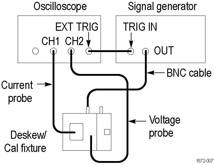
This fixture converts the oscilloscope PROBE COMPENSATION output (Probe Calibration on DPO7000C Series) or the TEK-DPG pulse generator output into a set of test point connections. These connections provide you with a convenient way to compensate for timing differences between voltage and current probes.
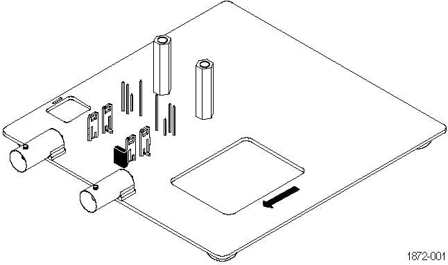
You can also optimize the instrument gain and offset accuracy at the probe tips for both voltage and current probes. Use the table as a guide to connect a variety of Tektronix voltage and current probes together on the fixture.
Connecting to the instrument
The fixture has two BNC inputs, Port A and Port B. The jaw size of the current probes and the operation that you want to perform determine which input to use. Use the included BNC cable to connect the fixture input to the Probe Calibration output of your DPO7000C instrument or to an external generator. Other TekVPI oscilloscope models, including the MDO3000 and MDO4000C series, 3 Series MDO and 4/5/6 Series B MSO, require the TEK-DPG pulse generator or an external generator as the signal source.
 | CAUTION:The maximum allowable voltage applied to either input is 8 V RMS. Voltages in excess of 8 V RMS can damage the fixture. |
Passive voltage probes fixture input guide
The following table supports P6139B, P5050B, TPP0250 TPP0500B, TPP1000, and other 10X passive probes. Not all probes are usable with all instruments. Gain and offset calibration is generally not needed for these probes.
| Operation | Input |
|---|---|
| Low frequency compensation | B |
| Gain and offset calibration (remove jumper from fixture to perform this operation) | B |
| Compensate timing with respect to current probes | A/B (use Port A for small current probes, Port B for large) |
Active voltage probes fixture input guide
The following table supports TAP1500, TAP2500, TAP3500, TAP4000, TDP0500, TDP1000, TDP1500, TDP3500, TDP4000, P6243, P6245, P6247, P6248, and P6251 probes. Not all probes are usable with all instruments.
| Operation | Input |
|---|---|
| Gain and offset calibration (remove jumper from fixture to perform this operation) | B |
| Compensate timing with respect to current probes | A/B (use Port A for small current probes, Port B for large) |
High voltage probes fixture input guide
The following table supports P5200A, P5205A, P5210A (requires external signal source), THDP0200, TMDP0200, and THDP0100 probes. Not all probes are usable with all instruments.
| Operation | Input |
|---|---|
| Gain and offset calibration (remove jumper from fixture to perform this operation) | B |
| Compensate timing with respect to current probes | A/B (use Port A for small current probes, Port B for large) |
Current probes fixture input A guide
The following table supports TCP0030A, TCP0020, TCP2020, TCP202A, TCP312A, and TCP305A probes. Not all probes are usable with all instruments.
| Operation | Input |
|---|---|
| Gain and offset calibration | A |
| Compensate timing with respect to current probes | A |
Current probes fixture input B guide
The following table supports TCP303 and TCP0150 probes. Not all probes are usable with all instruments.
| Operation | Input |
|---|---|
| Gain and offset calibration | B |
| Compensate timing with respect to current probes | B |
Connecting probes
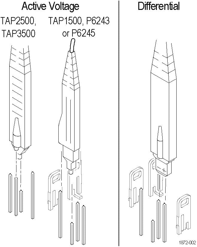
The following diagrams show how to attach each type of probe tip to the fixture. Refer to the ground symbols on the fixture to establish the correct polarity.
| WARNING:To avoid personal injury, use care while connecting probe tips to the square pins on the fixture. The ends of the square pins are sharp. |
Active Voltage or Differential probes
For Active Voltage probes (TAP1500, TAP2500, TAP3500, TAP4000, P6243, or P6245), connect the probe tip to the short pin and the probe ground to the long pin as shown.
For Differential probes (TDP0500, TDP4000, TDP3500, TDP1000, TDP1500, P6247, P6248, or P6251), connect the probe + input to the signal pin and the probe – input to the ground pin as shown. There is no connection to the probe ground input.
Passive Voltage or High Voltage probes
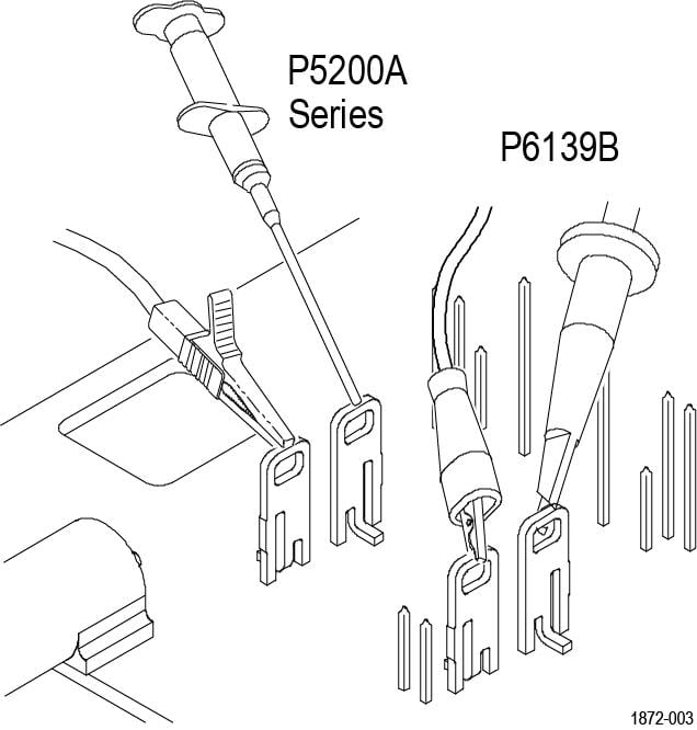
For P6139B or P5200 Series probes, connect the probe tip and the ground lead to the two terminals as shown.
Current probes
For TCP0030A, TCP0020, TCP2020, TCP202A, TCP312A, TCP305A, TCP0150, and TCP303 probes, connect the current probe around the current loop as shown. Be sure to align the polarity arrows on the current probe and the fixture, and make sure the current probe slider is closed and locked.

Using the fixture
Perform the following steps to use the fixture. For best results, warm up the equipment for 20 minutes before performing these functions.
Optimize Gain and Offset Accuracy
Not all oscilloscopes support this function.
- Connect the Port A or Port B side of the fixture to the instrument, depending on the probe type. If you are optimizing the gain and offset accuracy for a voltage probe on Port B, remember to remove the small jumper over the two pins on the fixture.
- Connect the probe to the fixture as described in Connecting Probes.
- Initiate the Calibrate Probe routine.
- When the routine is finished, remove the connections and replace the small jumper across the two pins on the fixture. Leave the jumper installed for all other functions.
Compensate probe timing (Deskew)
- Connect the Port A or Port B side of the fixture to the instrument, depending on the probe type.
- Connect the probes to the fixture.
- Display all channels that you want to deskew.
- Push the AUTOSET button on the instrument front panel.
- Adjust vertical SCALE and POSITION for each channel so that the signals overlap and are centered on-screen (with active probes, adjusting offset may be required).
- Adjust horizontal POSITION so that a triggered rising edge is at center screen.
- Adjust horizontal SCALE so that the differences in the channel delays are clearly visible.
- Adjust horizontal POSITION again so that the first rising edge is exactly at center screen. The fastest probe is connected to this channel. The fastest probe is probably the one with the shortest cable or the highest bandwidth.
- Touch the VERT button or use the Vertical menu to display the vertical control window.
- Touch the Probe Deskew button to display the channel-deskew control window.
- Select one of the slower channels. If possible, perform the next step at a signal amplitude within the same attenuator range (vertical scale) as your planned signal measurements. Any change to the vertical scale after deskew is complete may introduce a new attenuation level (you can generally hear attenuator settings change) and therefore a slightly different signal path. This different path may cause up to a 200 ps variation in timing accuracy between channels.
- Adjust the deskew time for that channel so that the signal aligns with that of the fastest channel.
- Repeat steps 11 and 12 for each additional channel that you want to deskew.
- Remove the connections.
Schematics
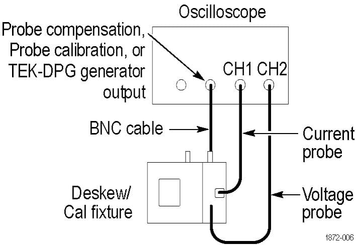
The schematic diagrams that follow show typical connections for both small and large style current probes.
| CAUTION:The maximum allowable voltage applied to either fixture input (Port A or Port B) is 8 V RMS. Voltages in excess of 8 V RMS may damage the fixture. |
Safety summary
To avoid potential hazards, use this product only as specified.
To avoid fire or personal injury, do not operate in wet/damp conditions.
Keep product surfaces clean and dry.
Refer to your probe manual for additional safety information.
Terms in this manual and on the product
These terms may appear in this manual:
| WARNING:Warning statements identify conditions or practices that could result in injury or loss of life. |
| CAUTION:Caution statements identify conditions or practices that could result in damage to this product or other property. |
These terms may appear on the product:
- DANGER indicates an injury hazard immediately accessible as you read the marking.
- WARNING indicates an injury hazard not immediately accessible as you read the marking.
- CAUTION indicates a hazard to property including the product.