Contact us
Call us at
Available 6:00 AM – 5:00 PM (PST) Business Days
Download
Download Manuals, Datasheets, Software and more:
Feedback
TMT4 Margin Tester Specification and Performance Verification Manual
This document contains the specifications and performance verification procedures for the TMT4 Margin Tester.
This manual applies to:
TMT4
By downloading, you agree to the terms and conditions of the Manuals Download Agreement.
Manuals Download Agreement
ATTENTION: please read the following terms and conditions carefully before downloading any documents from this website. By downloading manuals from Tektronix' website, you agree to the following terms and conditions:
Manuals for Products That Are Currently Supported:
Tektronix hereby grants permission and license to owners of Tektronix instruments to download and reproduce the manuals on this website for their own internal or personal use. Manuals for currently supported products may not be reproduced for distribution to others unless specifically authorized in writing by Tektronix, Inc.
A Tektronix manual may have been revised to reflect changes made to the product during its manufacturing life. Thus, different versions of a manual may exist for any given product. Care should be taken to ensure that one obtains the proper manual version for a specific product serial number.
Manuals for Products That Are No Longer Supported:
Tektronix cannot provide manuals for measurement products that are no longer eligible for long term support. Tektronix hereby grants permission and license for others to reproduce and distribute copies of any Tektronix measurement product manual, including user manuals, operator's manuals, service manuals, and the like, that (a) have a Tektronix Part Number and (b) are for a measurement product that is no longer supported by Tektronix.
A Tektronix manual may be revised to reflect changes made to the product during its manufacturing life. Thus, different versions of a manual may exist for any given product. Care should be taken to ensure that one obtains the proper manual version for a specific product serial number.
This permission and license does not apply to any manual or other publication that is still available from Tektronix, or to any manual or other publication for a video production product or a color printer product.
Disclaimer:
Tektronix does not warrant the accuracy or completeness of the information, text, graphics, schematics, parts lists, or other material contained within any measurement product manual or other publication that is not supplied by Tektronix or that is produced or distributed in accordance with the permission and license set forth above.
Tektronix may make changes to the content of this website or to its products at any time without notice.
Limitation of Liability:
TEKTRONIX SHALL NOT BE LIABLE FOR ANY DAMAGES WHATSOEVER (INCLUDING, WITHOUT LIMITATION, ANY CONSEQUENTIAL OR INCIDENTAL DAMAGES, DAMAGES FOR LOSS OF PROFITS, BUSINESS INTERRUPTION, OR FOR INFRINGEMENT OF INTELLECTUAL PROPERTY) ARISING OUT OF THE USE OF ANY MEASUREMENT PRODUCT MANUAL OR OTHER PUBLICATION PRODUCED OR DISTRIBUTED IN ACCORDANCE WITH THE PERMISSION AND LICENSE SET FORTH ABOVE.
Read Online
Important safety information
This manual contains information and warnings that must be followed by the user for safe operation and to keep the product in a safe condition.
To safely perform service on this product, see the Service safety summary that follows the General safety summary.
General safety summary
Use the product only as specified. Review the following safety precautions to avoid injury and prevent damage to this product or any products connected to it. Carefully read all instructions. Retain these instructions for future reference.
This product shall be used in accordance with local and national codes.
For correct and safe operation of the product, it is essential that you follow generally accepted safety procedures in addition to the safety precautions specified in this manual.
The product is designed to be used by trained personnel only.
Only qualified personnel who are aware of the hazards involved should remove the cover for repair, maintenance, or adjustment.
Before use, always check the product with a known source to be sure it is operating correctly.
This product is not intended for detection of hazardous voltages.
Use personal protective equipment to prevent shock and arc blast injury where hazardous live conductors are exposed.
While using this product, you may need to access other parts of a larger system. Read the safety sections of the other component manuals for warnings and cautions related to operating the system.
When incorporating this equipment into a system, the safety of that system is the responsibility of the assembler of the system.
To avoid fire or personal injury
Use proper power cord.
Use only the power cord specified for this product and certified for the country of use. Do not use the provided power cord for other products.
Ground the product.
This product is indirectly grounded through the grounding conductor of the mainframe power cord. To avoid electric shock, the grounding conductor must be connected to earth ground. Before making connections to the input or output terminals of the product,ensure that the product is properly grounded. Do not disable the power cord grounding connection.
Power disconnect.
The power cord disconnects the product from the power source. See instructions for the location. Do not position the equipment so that it is difficult to operate the power cord; it must remain accessible to the user at all times to allow for quick disconnection if needed.
Observe all terminal ratings.
To avoid fire or shock hazard, observe all rating and markings on the product. Consult the product manual for further ratings information before making connections to the product.
Do not operate without covers
Do not operate this product with covers or panels removed, or with the case open. Hazardous voltage exposure is possible.
Avoid exposed circuitry
Do not touch exposed connections and components when power is present.
Do not operate with suspected failures.
If you suspect that there is damage to this product, have it inspected by qualified service personnel.
Disable the product if it is damaged. Do not use the product if it is damaged or operates incorrectly. If in doubt about safety of the product, turn it off and disconnect the power cord. Clearly mark the product to prevent its further operation.
Examine the exterior of the product before you use it. Look for cracks or missing pieces.
Use only specified replacement parts.
Do not operate in wet/damp conditions
Be aware that condensation may occur if a unit is moved from a cold to a warm environment.
Do not operate in an explosive atmosphere
Keep product surfaces clean and dry
Remove the input signals before you clean the product.
Provide proper ventilation.
Refer to the installation instructions in the manual for details on installing the product so it has proper ventilation.
Slots and openings are provided for ventilation and should never be covered or otherwise obstructed. Do not push objects into any of the openings.
Provide a safe working environment
Always place the product in a location convenient for viewing the display and indicators.
Be sure your work area meets applicable ergonomic standards. Consult with an ergonomics professional to avoid stress injuries.
Use care when lifting and carrying the product. This product is provided with a handle or handles for lifting and carrying.
Terms in this manual
These terms may appear in this manual:
 | WARNING:Warning statements identify conditions or practices that could result in injury or loss of life. |
| CAUTION:Caution statements identify conditions or practices that could result in damage to this product or other property. |
Terms on the product
These terms may appear on the product:
- DANGER indicates an injury hazard immediately accessible as you read the marking.
- WARNING indicates an injury hazard not immediately accessible as you read the marking.
- CAUTION indicates a hazard to property including the product.
Symbols on the product
 | When this symbol is marked on the product, be sure to consult the manual to find out the nature of the potential hazards and any actions which have to be taken to avoid them. (This symbol may also be used to refer the user to ratings in the manual.) |
The following symbols(s) may appear on the product.
 |  |  |  |
Service safety summary
The Service safety summary section contains additional information required to safely perform service on the product. Only qualified personnel should perform service procedures. Read this Service safety summary and the General safety summary before performing any service procedures.
To avoid electric shock
Do not touch exposed connections.
Do not service alone
Do not perform internal service or adjustments of this product unless another person capable of rendering first aid and resuscitation is present.
Disconnect power
To avoid electric shock, switch off the product power and disconnect the power cord from the mains power before removing any covers or panels, or opening the case for servicing.
Use care when servicing with power on
Dangerous voltages or currents may exist in this product. Disconnect power, remove battery (if applicable), and disconnect test leads before removing protective panels, soldering, or replacing components.
Verify safety after repair
Always recheck ground continuity and mains dielectric strength after performing a repair.
Compliance information
This section lists the safety and environmental standards with which the instrument complies. This product is intended for use by professionals and trained personnel only; it is not designed for use in households or by children.
Compliance questions may be directed to the following address:
Tektronix, Inc.
PO Box 500, MS 19-045
Beaverton, OR 97077, USA
Safety compliance
This section lists the safety standards with which the product complies and other safety compliance information.
EU declaration of conformity – low voltage
Compliance was demonstrated to the following specification as listed in the Official Journal of the European Union:
Low Voltage Directive 2014/35/EU.
- EN 61010-1. Safety Requirements for Electrical Equipment for Measurement, Control, and Laboratory Use – Part 1: General Requirements
U.S. nationally recognized testing laboratory listing
- UL 61010-1. Safety Requirements for Electrical Equipment for Measurement, Control, and Laboratory Use – Part 1: General Requirements
Canadian certification
- CAN/CSA-C22.2 No. 61010-1. Safety Requirements for Electrical Equipment for Measurement, Control, and Laboratory Use – Part 1: General Requirements
Additional compliances
- IEC 61010-1. Safety Requirements for Electrical Equipment for Measurement, Control, and Laboratory Use – Part 1: General Requirements
Equipment type
Test and measuring equipment.
Safety class
Class 1 – grounded product.
Pollution degree description
A measure of the contaminants that could occur in the environment around and within a product. Typically the internal environment inside a product is considered to be the same as the external. Products should be used only in the environment for which they are rated.
- Pollution Degree 1. No pollution or only dry, nonconductive pollution occurs. Products in this category are generally encapsulated, hermetically sealed, or located in clean rooms.
- Pollution Degree 2. Normally only dry, nonconductive pollution occurs. Occasionally a temporary conductivity that is caused by condensation must be expected. This location is a typical office/home environment. Temporary condensation occurs only when the product is out of service.
- Pollution Degree 3. Conductive pollution, or dry, nonconductive pollution that becomes conductive due to condensation. These are sheltered locations where neither temperature nor humidity is controlled. The area is protected from direct sunshine, rain, or direct wind.
- Pollution Degree 4. Pollution that generates persistent conductivity through conductive dust, rain, or snow. Typical outdoor locations.
Pollution degree rating
Pollution Degree 2 (as defined in IEC 61010-1). Rated for indoor, dry location use only.
IP rating
IP20 (as defined in IEC 60529).
Measurement and overvoltage category descriptions
Measurement terminals on this product may be rated for measuring mains voltages from one or more of the following categories (see specific ratings marked on the product and in the manual).
- Overvoltage Category I. For equipment intended to be connected to a mains supply in which means have been taken to substantially and reliably reduce transient overvoltages to a level where they cannot cause a hazard.
- Measurement Category II. For measurements performed on circuits directly connected to the low-voltage installation.
- Measurement Category III. For measurements performed in the building installation.
- Measurement Category IV. For measurements performed at the source of low-voltage installation.
| Note:Only mains power supply circuits have an overvoltage category rating. Only
measurement circuits have a measurement category rating. Other circuits within the
product do not have either rating. |
Mains overvoltage category rating
Overvoltage Category II (as defined in IEC 61010-1).
Environmental compliance
This section provides information about the environmental impact of the product.
Product end-of-life handling
Observe the following guidelines when recycling an instrument or component:
- Equipment recycling
- Production of this equipment required the extraction and use of natural resources. The equipment may contain substances that could be harmful to the environment or human health if improperly handled at the product’s end of life. To avoid release of such substances into the environment and to reduce the use of natural resources, we encourage you to recycle this product in an appropriate system that will ensure that most of the materials are reused or recycled appropriately.
 |
This symbol indicates that this product complies with the applicable European Union requirements according to Directives 2012/19/EU and 2006/66/EC on waste electrical and electronic equipment (WEEE) and batteries. For information about recycling options, check the Tektronix Web site (http://www.tek.com/productrecycling). |
- Battery recycling
- Perchlorate materials
- This product contains one or more type CR lithium batteries. According to the state of California, CR lithium batteries are classified as perchlorate materials and require special handling. See www.dtsc.ca.gov/hazardouswaste/perchlorate for additional information.
Transporting batteries
The small lithium primary cell contained in this equipment does not exceed 1 gram of lithium metal content per cell.
The cell type has been shown by the manufacturer to comply with the applicable requirements of the UN Manual of Tests and Criteria Part III, Sub-section 38.3. Consult your carrier to determine which lithium battery transportation requirements are applicable to your configuration, including to its re-packaging and re-labeling, prior to reshipment of the product by any mode of transport.
Specifications
All specifications are typical.
High density bidirectional signal system
- Number of lanes
- Supports 1, 4, 8, 16 lanes
- Insertion loss budget, Mixed mode
-
8 GT/s and 16 GT/s channel insertion loss budget at Nyquist by system component:
Insertion loss component At 4 GHz, Typical At 8 GHz, Typical TMT4 adapter 1.4 2.6 TMT4 cable adapter 1.4 3.0 CEM Edge x 1 adapter 0.5 1.5 CEM Edge x 4 adapter 0.5 1.5 CEM Edge x 8 adapter 0.5 1.5 CEM Edge x 16 adapter 0.5 1.5 CEM Slot x 16 adapter 7.1 13.5 M.2 Edge adapter1 1.6 3.5 M.2 Slot adapter 7.5 13.5 U.2 Edge adapter 1.3 1.9 U.2 Slot adapter 5.3 10.0 U.3 Edge adapter 1.1 1.6 U.3 Slot adapter 5.4 10.0
- Supported protocols
- PCIe generation 3 and 4 speeds
- Power capability
- 75 W of power through 3.3 V and 12 V lines per PCIe CEM specifications.
PCIe signal system
- Absolute maximum input voltage
-
Maximum peak-to-peak differential input voltage VID input voltage: 1.2 V
PCIe compliant measured at TP2.
Reference clock
- Input characteristics
- 85 Ω differential system
- Input frequency
- PCIe compliant reference clock including 100 MHz common clock or SSC enabled (30 - 33 kHz)
- Absolute max input voltage
- 1.15 V
- Absolute min input voltage
- - 0.3 V
- Peak - to - peak differential input voltage
- 0.3 V - 1.5 V
- Output characteristics
- 85 Ω differential source terminated system
- Output frequency
- PCIe compliant reference clock including 100 MHz common clock or SSC enabled (30 - 33 kHz)
- Output frequency accuracy
- 100 MHz reference clock with ±300 ppm frequency stability
Trigger system
- Input characteristics
- 50 Ω single ended
- Input max voltage
- 3.3 V
- Output characteristics
- 50 Ω single ended
- Output max voltage
- 1.25 V with 50 Ω loading
- Trigger Input
-
HIGH to LOW transition with at least 1.8 V to 0. The signal must have a width of at least 40 μs.
- Trigger Output
- HIGH to LOW transition indicates the trigger event occurred.
Controls and indicators
- Front power button
-
Button to power unit on/off
- Off: Unplugged
- Amber: Standby
- Blue: On
Communication ports
- USB
- Supports Type A USB 2.0 and compatible devices..
- LAN port
- 10/100/1000 Base-T Ethernet
- SD slot
- This slot will be used for core storage needs. Removable for sensitive purposes related to declassification as needed.
Ground strap attachment
- Ground strap attachment
- Grounding protection input available for ground strap.
Power source
- Power source
- 240 W
Mechanical characteristics
- Weight
- 3.13 kg (6.89 lbs) stand-alone instrument
- Overall Dimensions
-
Dimension With protective cover and handle and feet No protective cover, with 50 Ω terminators Height 150 mm 147 mm Width 206 mm 200 mm Depth 286 mm 277 mm
Performance verification procedure
The following procedure verifies the end-to-end PCIe link for TMT4 → TMT4 cable → TMT4 adapter → PCIe enabled device. A failing result can indicate a fault in any one of those components in the system. Additional troubleshooting may be required to identify any cause of fault.
Test equipment
- TMT4 cable
- CEM x16 Slot adapter
- PCIe x16 Gen 3/4 complaint CEM add-in card endpoint
- External power supply for add-in card endpoint (if needed)
- Ethernet cable
- PC with Web browser
Procedure
- Log in to the instrument through the Web interface and click the Utilities tab.
- Click the Run Self Test button to run a self test.
- Check the results of the self test that appear in the window once the test completes. You can also choose to save the test log files by clicking Export Log Files.
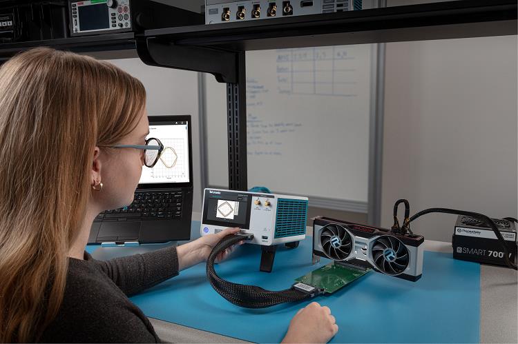
-
Connect the TMT4 to a PCIe x16 Gen3/4 compliant CEM add-in card endpoint. If required, use an external power source to power the add-in. The following image shows a setup example using an external power source for a graphics card.
- Check that the Adapter Power LED is lit on the CEM x16 Slot adapter.
- Click the Check Link button on the bottom of the navigation panel in the Web interface.
-
Verify the link connection. A failed link shows red text that states "No link". A good link shows green text.

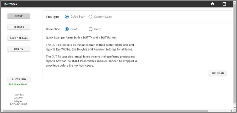
- Click the Setup button and verify that the system is in the correct setup to run your connected add-in card scans. If needed, reboot the TMT4 to AIC setup. A Reboot button should appear if this is needed.
- Set the Test Type to Quick Scan.
- Set the Generation to Gen3.
-
Click the Run Scan button.
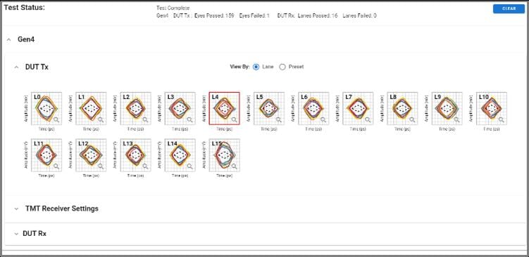
- Once the test begins, the Results Test Status screen will automatically be displayed. Verify you can see the following:
-
Eye diagrams for all 16 lanes. If there are any fewer than 16 lanes, that is considered a failure.
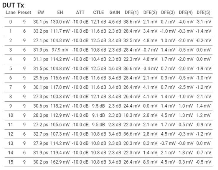
-
Click on the TMT Receiver Settings expandable menu to view the results table. The table shows the preset each lane is trained to and the expected test range based on the negotiated preset. If any errors are found, they will show in the table as red text.
-
- If no failures are found, run a Quick Scan for Gen 4. The procedure is the same.
- If failures are found, troubleshoot as follows:
- Verify fully seated connections (unplug and replug).
- Verify external power is attached and on as needed by the DUT.
- Once troubleshooting is complete, run the Gen 3 Quick Scan again.
Help us improve our technical documentation. Provide feedback on our TekTalk documentation forum.