

Contact us
Live Chat with Tek representatives. Available 6:00 AM - 4:30 PM
Call us at
Available 6:00 AM – 5:00 PM (PST) Business Days
Download
Download Manuals, Datasheets, Software and more:
Feedback
TPP0502 Instructions
This manual describes the setup and use of the 500 MHz 2X Passive Probe and related accessories.
This manual applies to:
TPP0502 0
Related Product Information
Bằng cách tải xuống, bạn đồng ý với các điều khoản và điều kiện của Thỏa thuận Tải xuống Hướng dẫn sử dụng.
Thỏa thuận Tải xuống Tài liệu Hướng dẫn
CHÚ Ý: vui lòng đọc kỹ các điều khoản và điều kiện sau trước khi tải xuống bất kỳ tài liệu nào từ trang web này. Bằng cách tải xuống hướng dẫn sử dụng từ trang web của Tektronix, bạn đồng ý với các điều khoản và điều kiện sau:
Hướng dẫn sử dụng cho các sản phẩm hiện đang được hỗ trợ:
Tektronix theo đây cấp phép và quyền cho chủ sở hữu các thiết bị Tektronix được tải xuống và sao chép các tài liệu hướng dẫn trên trang web này cho mục đích sử dụng nội bộ hoặc cá nhân của riêng họ. Tài liệu hướng dẫn cho các sản phẩm hiện đang được hỗ trợ không được sao chép để phân phối cho người khác trừ khi được Tektronix, Inc. cấp phép bằng văn bản cụ thể.
Hướng dẫn sử dụng của Tektronix có thể đã được sửa đổi để phản ánh các thay đổi được thực hiện đối với sản phẩm trong vòng đời sản xuất của sản phẩm đó. Do đó, các phiên bản hướng dẫn sử dụng khác nhau có thể tồn tại đối với bất kỳ sản phẩm cụ thể nào. Cần cẩn thận để đảm bảo rằng người dùng có được phiên bản hướng dẫn sử dụng phù hợp cho số sê-ri sản phẩm cụ thể.
Tài liệu hướng dẫn cho các sản phẩm không còn được hỗ trợ:
Tektronix không thể cung cấp tài liệu hướng dẫn cho các sản phẩm đo lường không còn đủ điều kiện hỗ trợ lâu dài. Tektronix theo đây cấp phép và quyền cho người khác sao chép và phân phối các bản sao của bất kỳ tài liệu hướng dẫn sản phẩm đo lường nào của Tektronix, bao gồm tài liệu hướng dẫn sử dụng, tài liệu hướng dẫn vận hành, tài liệu hướng dẫn dịch vụ và tương tự, mà (a) có Số bộ phận của Tektronix và (b) dành cho sản phẩm đo lường không còn được Tektronix hỗ trợ.
Tài liệu hướng dẫn của Tektronix có thể được sửa đổi để phản ánh các thay đổi được thực hiện đối với sản phẩm trong vòng đời sản xuất. Do đó, các phiên bản tài liệu hướng dẫn khác nhau có thể tồn tại cho bất kỳ sản phẩm cụ thể nào. Cần thận trọng để đảm bảo rằng người dùng có được phiên bản tài liệu hướng dẫn phù hợp cho số sê-ri sản phẩm cụ thể.
Giấy phép và quyền này không áp dụng cho bất kỳ tài liệu hướng dẫn hoặc ấn phẩm nào khác vẫn có sẵn từ Tektronix, hoặc cho bất kỳ tài liệu hướng dẫn hoặc ấn phẩm nào khác dành cho sản phẩm sản xuất video hoặc sản phẩm máy in màu.
Tuyên bố miễn trừ trách nhiệm:
Tektronix không đảm bảo tính chính xác hoặc đầy đủ của thông tin, văn bản, đồ họa, sơ đồ mạch, danh sách bộ phận hoặc tài liệu khác có trong bất kỳ hướng dẫn sử dụng sản phẩm đo lường nào hoặc ấn phẩm khác không do Tektronix cung cấp hoặc được sản xuất hoặc phân phối theo sự cho phép và giấy phép nêu trên.
Tektronix có thể thay đổi nội dung của trang web này hoặc các sản phẩm của mình bất cứ lúc nào mà không cần thông báo.
Giới hạn Trách nhiệm pháp lý:
TEKTRONIX SẼ KHÔNG CHỊU TRÁCH NHÁCH VỀ BẤT KỲ TỆN HẠI NÀO (BAO GỒM, KHÔNG GIỚI HẠN, BẤT KỲ TỆN HẠI DO HẬU QUẢ HOẶC NGẪU NHIÊN, TỆN HẠI DO MẤT LỢI NHUẬN, GIÁN ĐOẠN KINH DOANH, HOẶC DO VI PHẠM QUYỀN SỞ HỮU TRÍ TUỆ) PHÁT SINH TỪ VIỆC SỬ DỤNG BẤT KỲ TÀI LIỆU HƯỚNG DẪN SẢN PHẨM ĐO LƯỜNG HOẶC ANH PHẨM NÀO KHÁC DO TEKTRONIX SẢN XUẤT HOẶC PHÂN PHỐI THEO GIẤY PHÉP VÀ QUYỀN NÊU TRÊN.
Read Online
Operating information
The TPP0502 2X Passive Probe is a high impedance probe with 2X attenuation that is designed for use with Tektronix FlexChannel™ and MDO3000, MDO/MSO/DPO4000B, MSO/DPO5000 series ground-referenced oscilloscopes.
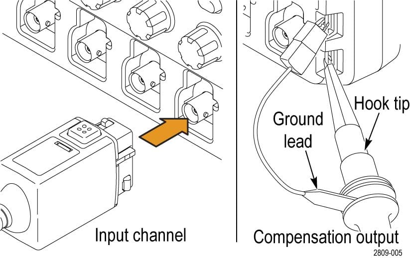
Compensating the probe
You should compensate the probe after you attach it to an oscilloscope for the first time, or after you have changed the probe tip cartridge.
- Connect the probe to an oscilloscope channel.
- Connect the probe tip and ground to the probe compensation terminals on the oscilloscope.
When using the MMCX tip (206-0666-xx), the following part numbers are required to connect the tip to the Probe Comp connections: 131-9717-xx (1), 196-3434-xx (1), and 206-0569-xx (2). See Connecting the MMCX tip to the oscilloscope Probe Comp.
- On FlexChannel™ instruments:
- Double tap the Channel Badge for the connected probe.
- Select the Probe Setup.
- Select Compensate Probe.
- Select Compensate Probe in the pop-up window.
- On MSO/DPO5000 instruments:
- Select Vertical > Probe Cal....
- Select the tab of the channel for the connected probe.
- In the Calibration section, click Calibrate Probe.
- On MDO3000 and MDO/MSO/DPO4000B instruments:
- Press the Channel Menu front panel button for the channel that you connected the probe to.
- Push the More button until Probe Setup is selected.
- Push the Calibrate Probe button and follow the on-screen instructions.
If the probe compensation fails, verify that the signal and ground connections are secure at the Probe Comp connections on the oscilloscope. Also check that the ground connection is secure at the probe head, the rigid, MMCX, or pogo tip is secured tightly in the probe head, and the hook tip is securely connected to the tip.
Standard accessories
 | WARNING:To avoid electric shock when using the probe or accessories, keep fingers behind the finger guard of probe body and accessories. |
| Item | Description |
|---|---|
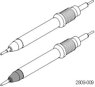 | Probe tips – pogo (white) and rigid (gray): The white pogo tip is pre-installed on the probe, and is spring-loaded for compliant testing of circuit boards. Reorder Tektronix part numbers below: |
| 206-0641-XX (rigid tip) | |
| 206-0642-XX (pogo tip) | |
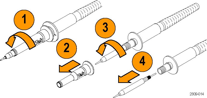
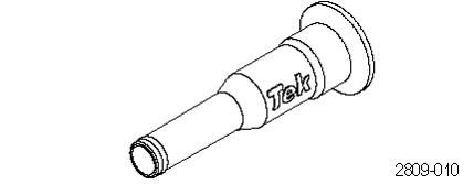 | Insulator sleeve: Remove this sleeve to replace the probe tips. |
| Reorder Tektronix part number: 342-1194-XX | |
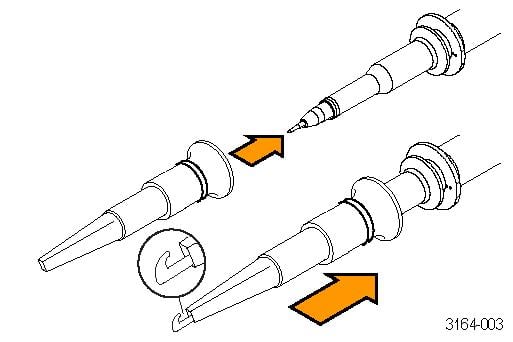 | Hook tip: Press the hook tip onto the probe tip and then clamp the hook onto the circuit. |
| Rating: 300 V CAT II | |
| Reorder Tektronix part number: 013-0362-XX | |
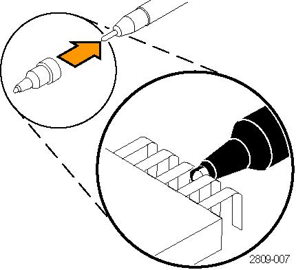 | Universal IC cap: Use this cap to prevent shorting the probe tip between IC pins. Snap the cap onto the probe tip, and then spin the cap to expose the probe tip toward the IC lead. |
| Reorder Tektronix part number: 013-0366-XX | |
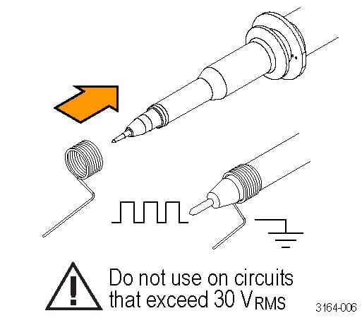 | Ground springs: To limit aberrations on high frequency signals caused by ground path inductance,bend the spring to reach nearby ground connections (<0.75 in, long; <0.25 in, short). Reorder Tektronix part numbers: |
| 016-2028-XX (long, 2 ea.) | |
| 016-2034-XX (short, 2 ea.) | |
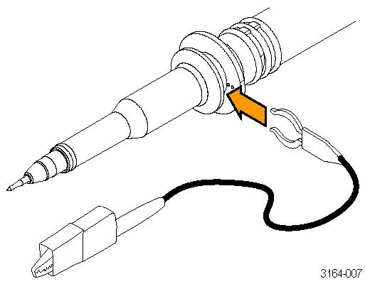 | Ground lead, with alligator clip: Secure the lead to the probe head ground and then to your circuit ground. |
| Reorder Tektronix part number 196-3521-XX | |
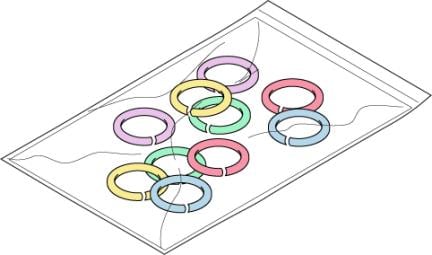 | Color bands: Use these bands to identify the oscilloscope channel at the probe head. |
| Reorder Tektronix part number 016-0633-XX (5 pairs) |
Optional accessories
The accessories shown below are available for the probes and are rated ≤30 V unless indicated otherwise.
| Description | Part number | |
|---|---|---|
| MMCX probe tip (gold) |
 | 206-0666-XX |
| MMCX to 0.1-inch (2.54 mm) square pin adapter (blue), 0.025-inch (0.635 mm) sq. pins |
 | 131-9717-XX |
| MMCX to 0.062 inch (1.57 mm) square pin adapter (white), 0.016 - 0.018 inch (0.4 - 0.46 mm) sq. pins |
 | 131-9677-XX |
| Micro hook tip, rating 300 V CAT II |
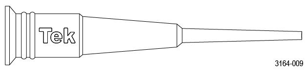 | 013-0363-XX |
| Electrical Y-Lead |
 | 196-3434-XX |
| MicroCKT test tip |
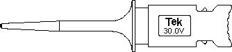 | 206-0569-XX |
| BNC to tip adapter, unterminated |
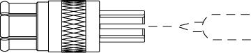 | 013-0367-XX |
| Circuit board test point/PCB adapter |
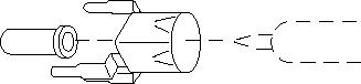 | 016-2016-XX |
| Chassis-Mount Probe Test Jack |
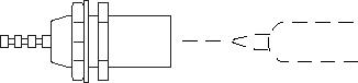 | 131-4210-XX |
| 6” clip-on ground lead |
 | 196-3198-XX |
| 12” alligator ground lead |
 | 196-3512-XX |
| Wire, spool, 32 AWG |
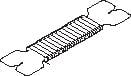 | 020-3045-XX |
| DUT Interface pin kit with (qty. 20) 0.018 inch (0.46 mm) round solder-in pins |
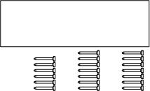 | 020-3169-XX |
| Probe tip tripod support with living hinge, 2 each (pictured with the probe tip and adapter attached) |
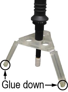 | 352-1170-XX |
| Solder aid for 0.062-inch (1.57 mm) pitch square pins, 0.016 - 0.018-inch (0.4 - 0.46 mm) sq. pins |
 | 003-1946-XX |
Interchanging the probe tip
For optimal performance, do a probe compensation after the tip has been replaced.
Only use tips with the light red-colored tail section for the TPP0502 probe; other tips will degrade performance.
| WARNING:To reduce the risk of shock, disconnect the probe before changing the probe tips. |
Connecting the MMCX tip to the Probe Comp
| WARNING:To avoid electric shock, disconnect the probe before connecting accessories. |
| Item | Description |
|---|---|
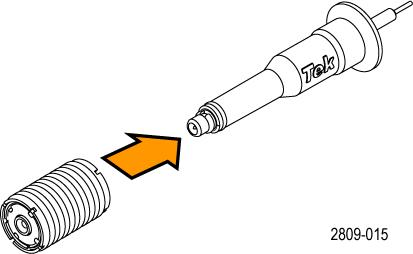 | Connect the MMCX tip to adapter: The MMCX adapter (131-9717-xx) snaps onto the MMCX tip. |
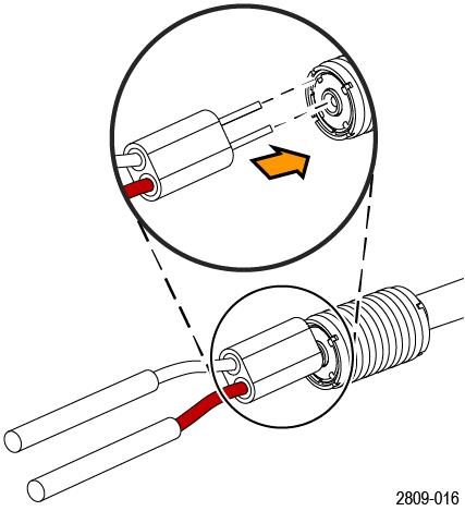 | Connect the Y–lead to MMCX adapter: Push the Y–lead (196-3434-xx) adapter into the MMCX adapter until it is seated. The signal input (red) connects to the center of the MMCX adapter. |
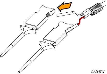 | Connect the MicroCKT test tips to Y-lead: Push the Y-lead into the handles of the MicroCKT test tips (206-0569-xx). |
Connect the MicroCKT test tips to Probe Comp terminals: Attach the two MicoCKT test tips to the Probe Comp terminals on the oscilloscope front panel.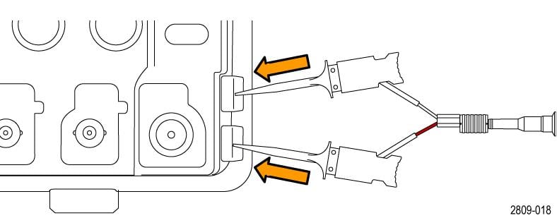 | |
| MMCX tip, adapter, and Y-lead is limited to 30 Vrms, 42 Vpk, 60 VDC, and OVT <500 Vpk. | |
Specifications
| Characteristic | Description |
|---|---|
| Bandwidth (–3 dB) | 500 MHz |
| System rise time (typical) | <700 ps |
| System input capacitance | Rigid tip: 12.7 pF |
| Pogo pin tip: 13.6 pF | |
| MMCX tip: 13.0 pF | |
| System attenuation accuracy | 2:1 ±2.2% |
| System input resistance @DC | 2 MΩ ±2% |
| Propagation delay | ~5.7 ns |
| Maximum input voltage | 300 VRMS CAT II |
| Cable length | 1.3 m |
| Weight (includes accessories and packaging) | <454 gm (1.0 lb) |
| MMCX tip, adapter, and Y-lead is limited to 30 Vrms, 42 Vpk, 60 VDC, and OVT <500 Vpk. | |
Performance graphs
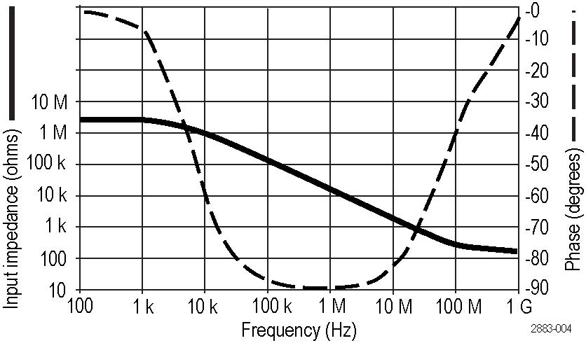
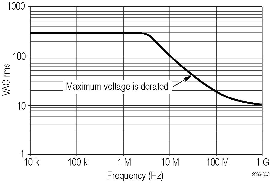
Environmental specifications
| Characteristic | Description |
|---|---|
| Temperature | Operating: –15 °C to +65 °C (+5 °F to +149 °F) |
| Non operating: –62 °C to +85 °C (–80 °F to +185 °F) | |
| Humidity | Operating: 5% to 95% relative humidity (%RH) up to +30 °C, 5% to 75% RH above +30 °C up to +65 °C. Non condensing |
| Non operating: 5% to 45% RH above +65 °C up to +85 °C. Non condensing | |
| Altitude | Operating: 3.0 km (9,842 ft) maximum |
| Non operating: 12.2 km (40,000 ft) maximum |
Safety compliance
This section lists the safety standards with which the product complies and other safety compliance information.
EU declaration of conformity – low voltage
Compliance was demonstrated to the following specification as listed in the Official Journal of the European Union:
Low Voltage Directive 2014/35/EU.
- EN 61010-031. Particular requirements for handheld probe assemblies for electrical measurement and test equipment
U.S. nationally recognized testing laboratory listing
- UL 61010-031. Particular requirements for handheld probe assemblies for electrical measurement and test equipment
Canadian certification
- CAN/CSA-C22.2 No. 61010-031. Particular requirements for handheld probe assemblies for electrical measurement and test equipment
Additional compliances
- IEC 61010-031. Particular requirements for handheld probe assemblies for electrical measurement and test equipment
- IEC 61010-2-032. Particular requirements for handheld current clamps for electrical measurement and test equipment
Pollution degree rating
Pollution Degree 2. Do not operate in environments where conductive pollutants may be present (as defined in IEC 61010-1). Rated for indoor use only.
| Note:Only mains power supply circuits have an overvoltage category rating. Only measurement circuits have a measurement category rating. Other circuits within the product do not have either rating. |
Environmental compliance
This section provides information about the environmental impact of the product.
Product end-of-life handling
Observe the following guidelines when recycling an instrument or component:
- Equipment recycling
- Production of this equipment required the extraction and use of natural resources. The equipment may contain substances that could be harmful to the environment or human health if improperly handled at the product’s end of life. To avoid release of such substances into the environment and to reduce the use of natural resources, we encourage you to recycle this product in an appropriate system that will ensure that most of the materials are reused or recycled appropriately.
 |
This symbol indicates that this product complies with the applicable European Union requirements according to Directives 2012/19/EU and 2006/66/EC on waste electrical and electronic equipment (WEEE) and batteries. For information about recycling options, check the Tektronix Web site (http://www.tek.com/productrecycling). |
General safety summary
Use the product only as specified. Review the following safety precautions to avoid injury and prevent damage to this product or any products connected to it. Carefully read all instructions. Retain these instructions for future reference.
This product shall be used in accordance with local and national codes.
For correct and safe operation of the product, it is essential that you follow generally accepted safety procedures in addition to the safety precautions specified in this manual.
The product is designed to be used by trained personnel only.
Before use, always check the product with a known source to be sure it is operating correctly.
Use personal protective equipment to prevent shock and arc blast injury where hazardous live conductors are exposed.
While using this product, you may need to access other parts of a larger system. Read the safety sections of the other component manuals for warnings and cautions related to operating the system.
When incorporating this equipment into a system, the safety of that system is the responsibility of the assembler of the system.
To avoid fire or personal injury
Connect and disconnect properly
Do not connect or disconnect probes or test leads while they are connected to a voltage source.
Use only insulated voltage probes, test leads, and adapters supplied with the product, or indicated by Tektronix to be suitable for the product.
Connect the probe output to the measurement instrument before connecting the probe to the circuit under test. Connect the probe reference lead to the circuit under test before connecting the probe input. Disconnect the probe input and the probe reference lead from the circuit under test before disconnecting the probe from the measurement instrument.
Observe all terminal ratings
To avoid fire or shock hazard, observe all rating and markings on the product. Consult the product manual for further ratings information before making connections to the product.
Do not exceed the Measurement Category (CAT) rating and voltage or current rating of the lowest rated individual component of a product, probe, or accessory. Use caution when using 1:1 test leads because the probe tip voltage is directly transmitted to the product.
Do not apply a potential to any terminal, including the common terminal, that exceeds the maximum rating of that terminal.
Do not float the common terminal above the rated voltage for that terminal.
The measurement terminals on this product are not rated for connection to Category III or IV circuits.
Avoid exposed circuitry
Do not touch exposed connections and components when power is present.
Do not operate with suspected failures
If you suspect that there is damage to this product, have it inspected by qualified service personnel.
Disable the product if it is damaged. Do not use the product if it is damaged or operates incorrectly. If in doubt about safety of the product, turn it off and disconnect the power cord. Clearly mark the product to prevent its further operation.
Before use, inspect voltage probes, test leads, and accessories for mechanical damage and replace when damaged. Do not use probes or test leads if they are damaged, if there is exposed metal, or if a wear indicator shows.
Examine the exterior of the product before you use it. Look for cracks or missing pieces.
Use only specified replacement parts.
Do not operate in wet/damp conditions
Be aware that condensation may occur if a unit is moved from a cold to a warm environment.
Do not operate in an explosive atmosphere
Keep product surfaces clean and dry
Remove the input signals before you clean the product.
Probes and test leads
Before connecting probes or test leads, connect the power cord from the power connector to a properly grounded power outlet.
Keep fingers behind the protective barrier, protective finger guard, or tactile indicator on the probes. Remove all probes, test leads and accessories that are not in use.
Use only correct Measurement Category (CAT), voltage, temperature, altitude, and amperage rated probes, test leads, and adapters for any measurement.
| WARNING:To avoid electric shock, keep the probe wire as far from the tip and high voltage circuits as possible. The probe wire voltage rating is less than the probe tip voltage rating. Therefore the probe wire may not provide adequate protection. |
| WARNING:To avoid electric shock, do not use the probe if the wear indicator on the cable becomes visible. Contact Tektronix at tek.com for a replacement. |
Beware of high voltages
Understand the voltage ratings for the probe you are using and do not exceed those ratings. Two ratings are important to know and understand:
- The maximum measurement voltage from the probe tip to the probe reference lead.
- The maximum floating voltage from the probe reference lead to earth ground.
These two voltage ratings depend on the probe and your application. Refer to the Specifications section of the manual for more information.
| WARNING:To prevent electrical shock, do not exceed the maximum measurement or maximum floating voltage for the oscilloscope input BNC connector, probe tip, or probe reference lead. |
Ground-referenced oscilloscope use
Do not float the reference lead of this probe when using with ground-referenced oscilloscopes. The reference lead must be connected to earth potential (0 V).
Floating measurement use
Do not float the reference lead of this probe above the rated float voltage.
Service the probe and accessories
Go to tek.com/support to find information on contacting Tektronix Service Support.
Terms in this manual and on the product
These terms may appear in this manual:
| WARNING:Warning statements identify conditions or practices that could result in injury or loss of life. |
| CAUTION:Caution statements identify conditions or practices that could result in damage to this product or other property. |
These terms may appear on the product:
- DANGER indicates an injury hazard immediately accessible as you read the marking.
- WARNING indicates an injury hazard not immediately accessible as you read the marking.
- CAUTION indicates a hazard to property including the product.
Symbols on the product
 | When this symbol is marked on the product, be sure to consult the manual to find out the nature of the potential hazards and any actions which have to be taken to avoid them. (This symbol may also be used to refer the user to ratings in the manual.) |
The following symbols(s) may appear on the product.
 CAUTION: Refer to Manual |