Thermocouple Measurements
Thermocouples join two dissimilar metals that produce a voltage proportional to the temperature difference between the conductor ends. This voltage is then measured and compared to a reference within the measurement device, the cold junction compensation (CJC) sensor.
The CJC sensor compensates for the thermocouple effect at the connection of the thermocouple to the measurement circuitry. The IC or thermistor used as the CJC is measured by the instrument, and the thermocouple effect within the instrument is cancelled out from the measurement.
The Model 2110 DMM measures this voltage through the dedicated thermocouple inputs on its front panel (labeled “TC INPUT”). The main advantages of thermocouples lie in their low cost and high durability. However, they are weaker than other temperature measurement sensors in accuracy. The Model 2110 has support for J-, R-, S-, T-, E-, N-, B-, C-, and K-type thermocouples. Each type has a different operating temperature range and differences in use cases.
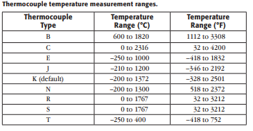
B-type thermocouples are more stable and work at higher temperatures.
C-Type ThermocouplesC-type thermocouples work well at extremely high temperatures, but not in the presence of oxygen.
E-Type ThermocouplesE-type thermocouples work well at very low temperatures and thus are well-suited for cryogenic applications.
J-Type ThermocouplesJ-type thermocouples have higher sensitivity, potentially increasing accuracy and precision.
K-Type ThermocouplesK-type thermocouples are the most commonly used due to their low price and wide range.
N-Type ThermocouplesN-type thermocouples deal with many of the effects of EMF that plague other thermocouple types.
R-Type ThermocouplesR-type thermocouples are well-suited for high temperatures and resist oxidation and reduction well.
S-Type ThermocouplesS-type thermocouples are more accurate and are good for use in high-temperature environments.
T-Type ThermocouplesT-type thermocouples have higher accuracies due to homogenous component wires (both copper) but have a narrower operational range.
The thermocouple measurement function can be activated on
the front panel through the following steps:
Set up the thermocouple measurement.
- Press SHIFT+TEMP.
Configure the measurement.
- Press CONFIG.
-
Use < or > button to select TCOUPL’s TYPE (K TYPE, J TYPE, R TYPE, S TYPE, T TYPE, E TYPE, N TYPE, B TYPE, or C TYPE), UNITS (°C, °F, or K), or RJUNCTION (REAL or SIMULATED) settings or to VIEW REAL (view the value read from the CJC).
The following SCPI commands mirror the operations described in the front panel operation:
- SENS:FUNC:TCO
- SENS:TCO:TYPE:<a>
where <a> is E, J, K, N, R, S, or T - SENS:TCO:UNIT: <name> where <name> is Far, Cel, or K
- SENS:TCO:RJUN:RSEL:<name> where <name> is REAL or SIM
- SENS:TCO:RJUN:REAL?
RTD (Resistance Temperature Detector) Measurements
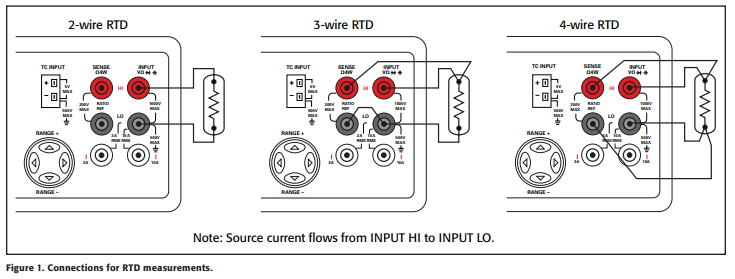
RTD sensors use a pure material with known temperature/ resistance behavior to determine the temperature at the probe. The Model 2110 DMM measures the resistance of the RTD element, compares it to known RTD resistance characteristics, and reports a voltage. See Figure 1 for setup instructions for different RTD characteristics.
RTDs are relatively accurate and tend to give repeatable measurements. However, they tend to be fragile and are not accurate at higher temperatures (greater than 600°C).
The RTD measurement function can be activated on the Model 2110 front panel via the following steps:
Set up the RTD measurement.
- Press TEMP.
Configure the measurement. - Press CONFIG.
- Use < or > button to select TEMP’s SENSOR (PT100, D100, F100, PT385, PT3916, USER, or SPRTD), UNITS (oC, oF, or K), or TRANSDUCER (4W RTD or 2W RTD).
Note: Select 4W RTD to measure a 3W RTD.
The following SCPI commands mirror the operations described in the Model 2110 front panel operation:
- SENS:FUNC:TEMP
- SENS:TEMP:RTD:<a> where <a> is PT100, D100, F100, P385, PT3916, USER, or SPRTD
- SENS:TEMP:UNIT: <name> where <name> is Far, Cel, or K
- SENS:TEMP:TRAN:<name> where <name> is FRTD or RTD
NTCT (Negative Temperature Coefficient Thermistor) Measurements
Thermistors are resistors whose values change with temperature. NTCTs are a subset of these thermistors in which resistance decreases with increasing temperature. The following equation (the Steinhart-Hart equation) shows the relationship between temperature (T) and resistance (R) when a, b, and c are thermistor parameters:
The Model 2110 DMM measures the R value and uses userdefined a, b, and c values to calculate T. An NTCT is best used in lower temperatures where accuracy is more important.
The NTCT measurement function can be activated on the Model 2110 front panel through the following steps:
Set up the NTCT measurement.
- Press TEMP.
- Press CONFIG.
- Use < or > button to select UNITS.
- Use < or > button to select TRANSDUCER.
- Use < or > button to select SENSOR.
a. Use < or > button to select NTCT.
b. Press ENTER.
c. Change the value of A using arrow keys.
d. Press ENTER twice.
e. Change the value of B using arrow keys.
f. Press ENTER twice.
g. Change the value of C using arrow keys.
h. Press ENTER.
Configure the measurement.
- Press CONFIG.
- Use < or > button to select UNITS (°C, °F, or K), or TRANSDUCER (4W RTD or 2W RTD).
The following SCPI commands mirror the operations described in the front panel operation:
- SENS:FUNC:TEMP
- SENS:TEMP:RTD:NTCT
- SENS:TEMP:UNIT:<name> where <name> is Far, Cel, or K
- SENS:TEMP:TRAN:<name> where <name> is FRTD or RTD