
Contact us
Call
Call us at
Available 6:00 AM – 5:00 PM (PST) Business Days
Download
Download Manuals, Datasheets, Software and more:
Feedback
TekExpress SATA Datasheet
TekExpress automated conformance test software is an application that automates SATA testing with Tektronix Windows-based instruments. TekExpress SATA provides a completely automated, simple, and efficient way to test SATA Gen1, Gen2, and Gen3 hosts and devices according to the requirements of the SATA-IW (Serial ATA Interoperability Working Group) as defined in accepted Methods of Implementation (MOI).
Key features
- 100% SATA Gen1, Gen2, and Gen3 Physical Layer Test Coverage for Hosts and Devices according to the latest UTD
- Performs all SATA Interoperability Program Approved Transmitter and Receiver Measurements
- SATA Receiver Margin Testing
- Significant Reduction in Testing Time through Automation
- Repeatable and Accurate Results
- Automatic Report Generation
Applications
- Device and Host Conformance to SATA Specifications
- PHY/TSG/OOB Transmitter Conformance Measurements
- RSG Receiver Conformance Measurements
- RMT (only pre-compiled waveform for AWG70K)
- Device and Host Validation
- Manufacturing Test and Factory Automation
TekExpress™ automated conformance test software
TekExpress SATA enables automated BIST-L negotiation, measurement analysis of the latest SATA United Test Document (UTD) and HTML-based report generation.
Support of all required SATA Gen1, Gen2, Gen3 PHY/SG/OOB measurements
100% automated -- save time and resources
There is no longer a need to be an expert on all the required instrument user interfaces. Remembering how to use the instrumentation is often time consuming and typically requires a senior engineer who monitors the test specification development. Even if you remember how to use all the instruments, it is common for even the most experienced operator to forget steps in the procedure, such as calibration, or setting up parameters correctly, such as clock recovery, only to have to restart the test. The TekExpress software takes the human element out of the equation and yields accurate and repeatable measurements every time. No need to spend hours in the lab testing a single device or configuring a single test instrument. Provided that automated DUT test state control (Loopback/BIST-L or BIST-T) is supported, a user can simply press the Run button in the TekExpress test automation system, and let the system run to completion without user intervention.
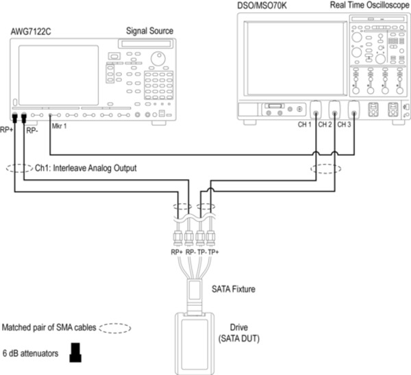
Setting up the bench
When setting up a test, nothing can be simpler than hooking up the test system by looking at a schematic. View the schematic of the selected test with a push of a button.
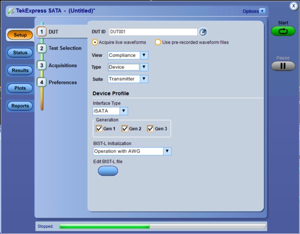
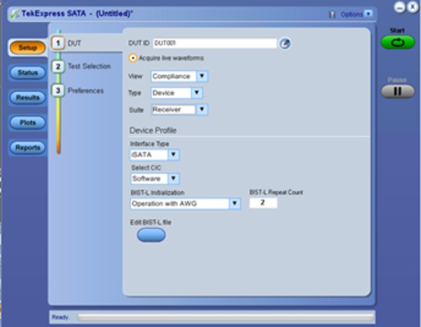
Host/Device testing to the i/u/mSATA electrical specifications
One button testing
Once the test bench is set up, the DUT is properly connected, and state control methods are established, simply press the Run button to perform the selected test suite.
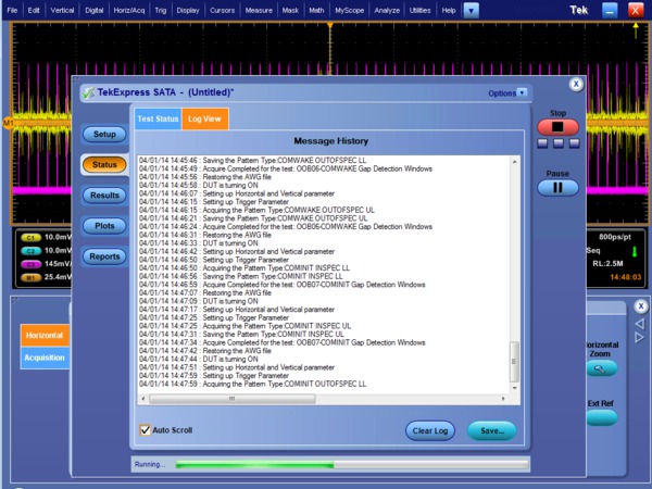
Step-by-step status view of BIST-L negotiation, pattern validation, signal acquisition and analysis
Online help and Show MOI
Online help is available through the Help menu and direct access to the approved SATA MOI (Method of Implementation) and UNH-IOL Physical Layer Test Suite through the Show MOI button. This allows users to understand the theory behind the measurements and better understand test results.
Pass fail report
The Report tab provides an HTML view of test results along with Pass/Fail status. Once testing is complete, an extensive report is automatically generated. If your report has a 100% passing score, your device can then be considered physical-layer conformant.
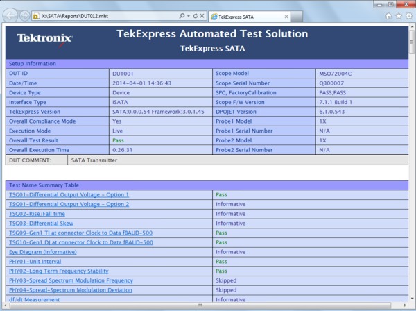
TekExpress Report with Setup Information, Summary View, Margin Analysis and Measurement Plots
100% SATA Gen1, Gen2, and Gen3 Physical Layer test coverage to the latest Unified Test Document (UTD)
Signaling Group (TSG), Physical Layer (PHY), Out-of-Bound (OOB), and Receiver Signaling Group (RSG). The TekExpress SATA software is an easy-to-use software package that automates 100% of the required SATA physical layer using the Tektronix multi-instrument test bench. The SATA test bench includes a real-time oscilloscope (DPO/MSO70000C/DX) and a high-performance signal generator(AWG7000C Series/AWG70000 Series).
Required test procedures (MOI) can be found at http://www.serialata.org.Now, using TekExpress SATA automated conformance test software, you can perform 100% of the physical layer tests performed in the 'Gold Suite' at SATA-IO Interop Workshops in your own lab.
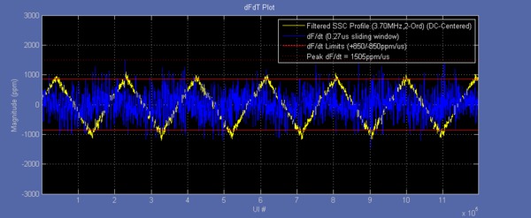
Comprehensive SSC Analysis Tools
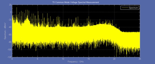
Transmitter Spectral Profile for Common Mode Analysis
TSG PHY OOB automation
For transmitter testing, TekExpress (Opt. SATA-TSG) performs all the tests required by the specification. SATA and SAS transmitter conformance measurements involve a multitude of complex measurements, including a unique vertical amplitude measurement.
Direct synthesis and device state control in a single instrument
An AWG700002B or AWG7000C Series arbitrary waveform generator with Option 01 (64M waveform length), Option 06 (24 GS/s interleaving), and Option 8 (Fast Sequencing) is a key component of the TekExpress Serial ATA Conformance Test Solution. It provides state control for the device or host under test as well as direct synthesis of the waveform patterns (impaired and unimpaired) needed for testing.
In SATA, state control is required to initiate a BIST-L (Built-In Self Test - Loopback) sequence to the device under test from its receiver port. This is used for all measurement test suites: transmitter and receiver. Other solutions attempt to initiate the BIST-L with an off-the-shelf host system or a digital generator and then try to apply the appropriate pattern for testing. This often requires the user to disconnect the BIST-L source from the device and then reconnect to a second source causing many devices to fall out of BIST-L mode. This leads to frequent rework and wasted time.
For signal impairment, alternative solutions require a multitude of sources to create the proper signal impairment (jitter and amplitude loss) for receiver testing. These include a pattern generator, a noise source, and a sinusoidal jitter source. This configuration is difficult to set up and even more difficult to duplicate reliably at different sites. With the AWG7000C Series, the signal impairment is synthesized digitally with a single setup file so it can be reproduced reliably. Further, it can also transition seamlessly from BIST-L initiation to a digitally impaired signal, a unique capability of a high-speed arbitrary waveform generator. TekExpress SATA-RSG allow operation from static, pre-configured waveforms, but for automated waveform generation the AWG will require Option SDX100 (SerialXpress) to be installed. Note that automated waveform generation is not supported over AWG70k series.
SATA reciever margin testing
- RSG-01 – Gen1 (1.5 Gb/s) Receiver Jitter Test
- RSG-02 – Gen2 (3.0 Gb/s) Receiver Jitter Test
- RSG-03 – Gen3 (6.0 Gb/s) Receiver Jitter Test
- RSG-05 – Asynchronous Receiver Stress Test
- RSG-06 – Asynchronous Receiver Stress Test with SSC
- RMT-01 – Gen1 (1.5 Gb/s) Receiver Margin Test
- RMT-02 – Gen2 (3.0 Gb/s) Receiver Margin Test
- RMT-03 – Gen3 (6.0 Gb/s) Receiver Margin Test
Option SATA-RSG offer full Receiver Margin Testing (RMT) capability. While the SATA RSG (Receive Signaling Group) test is a Pass/ Fail test on whether the receiver can tolerate a laboratory-grade impaired framed composite test signal, designers will want to know ‘how much margin do I have?’ TekExpress SATA software provides both a Pass/Fail RSG test and Receiver Margin Testing (RMT). When the RMT test is selected, jitter is synthesized at different frequencies and amplitudes increasingly until errors are detected on the frame error analyzer. A jitter tolerance curve is then created that shows where the device fails. This information is useful in validating the design of the receiver. On the fly Jitter synthesis is only done for AWG7k series. For AWG70k series the waveform needs to be pre-compiled and stored in a specified directory.
SATA Receiver testing
SATA Gen1, Gen2, and Gen3 6 Gb/s PHY/ TSG/OOB transmitter testing with TekExpress software
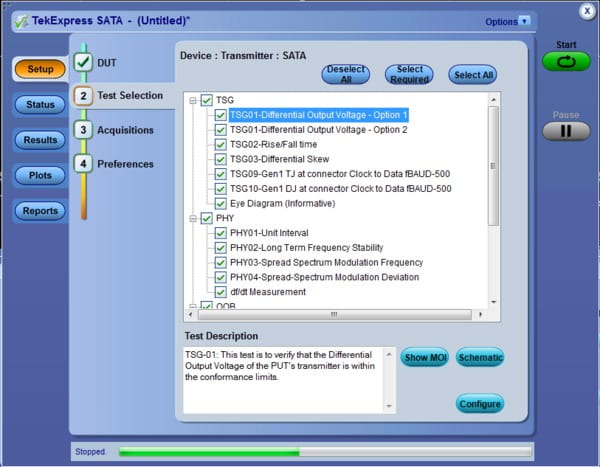
TekExpress (Opt. SATA-TSG) provides 100% automation of the SATA-IO approved PHY/TSG/OOB Method of Implementation (MOI). The software requires a DPO/MSO70000C/DX/SX oscilloscope (or other supported oscilloscope) equipped with DPOJET (Advanced Jitter Analysis) and AWG7000C Series arbitrary waveform generator. TekExpress SATA software (run on the DPO/MSO70000C/DX) sequences through the entire test suite. The AWG is used as the device state controller to put the device or host into BIST-L (Built-In Self Test – Loopback). The AWG then sends the proper patterns (LFTP, MFTP, LBP, and HFTP) for the PHY/TSG categories. The out-of-bound (OOB) measurements include testing the OOB signal thresholds, timing, as well as gap length and detection windows of COMINIT/RESET, COMWAKE, and COMINIT OOB signals. TekExpress SATA Opt. TSG also supports ‘semi-automated’ PHY/TSG/ OOB testing if the device under test supports the proper signaling without the use of an AWG.
PHY/TSG/OOB transmitter test suite
| PHY/TSG/OOB Transmitter | Description |
| PHY-01 | Unit Interval |
| PHY-02 | Frequency Long-term Stability |
| PHY-03 | Spread-spectrum Modulation Frequency |
| PHY-04 | Spread-spectrum Modulation Deviation |
| TSG-01 | Differential Output Voltage |
| TSG-02 | Rise/Fall Time |
| TSG-03 | Differential Skew |
| TSG-04 | AC Common Mode Voltage |
| TSG-05 | Rise/Fall Imbalance |
| TSG-06 | Amplitude Imbalance |
| TSG-09 | TJ at Connector, Clock to Data, Fbaud/500 (Gen1) |
| TSG-10 | DJ at Connector, Clock to Data, Fbaud/500 (Gen1) |
| TSG-11 | TJ at Connector, Clock to Data, Fbaud/500 (Gen2) |
| TSG-12 | DJ at Connector, Clock to Data, Fbaud/500 (Gen2) |
| TSG-13 | Transmit Jitter (Gen3i) |
| TSG-14 | Tx Maximum Differential Output Voltage Amplitude (Gen3i) |
| TSG-15 | Tx Minimum Differential Output Voltage Amplitude (Gen3i) |
| OOB-01 | OOB Signal Detection Threshold |
| OOB-02 | UI during OOB Signaling |
| OOB-03 | COMINIT/RESET and COMWAKE Transmit Burst Length |
| OOB-04 | COMINIT/RESET Transmit Gap Length |
| OOB-05 | COMWAKE Transmit Gap Length |
| OOB-06 | COMWAKE Gap Detection Windows |
| OOB-07 | COMINIT Gap Detection Windows |
Single setup for both PHY/TSG/OOB Transmitter and RSG/RMT Receiver Testing
SATA RSG-RTM receiver testing with TekExpress software
TekExpress (Opt. SATA-RSG) provides automation of the SATA-IO approved Receiver Signaling Group / Receiver Margin Test (RSG/RMT) MOI. A supported configuration includes a DPO/MSO70000C/DX Series oscilloscope (or other supported oscilloscope) equipped with DPOJET (Advanced Jitter Analysis), an AWG7000C Series arbitrary waveform generator, and a frame error analyzer. The TekExpress SATA software first initiates a BIST-L sequence to the device under test to put the device into loopback. After loopback is achieved and the loopback transmitter is transmitting good data to the frame error analyzer, the AWG sends jitter at the frequency tones and amplitudes defined in the specification to the receiver. If the frame error detector detects errors on the loopback channel, then the device fails the RSG test. Prior to the test, the oscilloscope is used to calibrate the impaired signal (jitter and amplitude) to be used in the test.
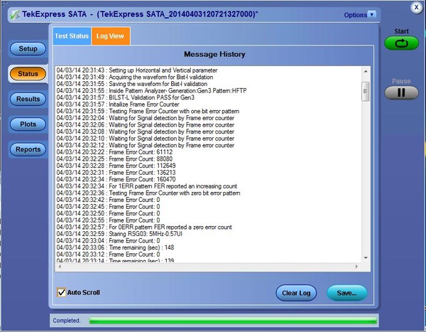
SATA RSG/RMT Test Status - Configuring and Verifying the Scope Error Detector
| RSG/RMT Receiver | Description |
| RSG-01 | Gen1 (1.5 Gb/s) Receiver Jitter Test |
| RSG-02 | Gen2 (3.0 Gb/s) Receiver Jitter Test |
| RSG-03 | Gen3 (6.0 Gb/s) Receiver Jitter Test |
| RSG-05 | Asynchronous Receiver Stress Test |
| RSG-06 | Asynchronous Receiver Stress Test with SSC |
| RMT-01 | Gen1 (1.5 Gb/s) Receiver Margin Test |
| RMT-02 | Gen2 (3.0 Gb/s) Receiver Margin Test |
| RMT-03 | Gen3 (6.0 Gb/s) Receiver Margin Test |
Complete device/host test system
TekExpress (Opt. SATA-DHB) provides complete automation of tests required for devices and hosts. It combines RSG/RMT and PHY/TSG/OOB tests using a DPO/MSO70000C/DX Series oscilloscope and an AWG7000C Series arbitrary waveform generator.
Ordering information
| Conformance testing | Models |
|---|---|
| SATA/SAS (6 Gb/s) | 12.5 GHz or higher bandwidth models |
Prerequisite host system software requirements
- Microsoft Windows XP OS with SP2 or later, or Windows 7 OS (64 bit support)
- Microsoft Excel 2002 or above
- Microsoft Explorer 6.0 SP1 or later
- Microsoft Photo Editor 3.0 or equivalent for viewing image files
- Adobe Reader 6.0 or equivalent software for viewing portable document format (PDF) files
SATA-TSG, SATA-RSG, SATA-DHB
SATA Physical-layer Test Application
| Model | New instrument orders | Product upgrades | Floating licenses |
|---|---|---|---|
| DPO/MSO70000C/DX/SX Series Real-Time Oscilloscope | Opt. SATA-TSG | DPO-UP SATA-TSG | DPOFL-SATA-TSG |
| Opt. SATA-RSG 12 | DPO-UP SATA-RSG | DPOFL-SATA-RSG | |
| Opt. SATA-DHB 3 | DPO-UP-SATA-DHB | DPOFL-SATA-DHB |
1Requires Option DJA (DPOJET Jitter and Eye Diagram Analysis) and 5XL record length (50 Million point memory). DJA is standard on MSO70000 Series oscilloscopes.
2Requires Opt. ERRDT and Opt. ST6G.
3Opt. SATA-DHB is a bundle of opt. SATA-TSG and opt. SATA-RSG.
Recommended test instruments
- DPO/MSO70000C/DX/SX Series Real-Time Oscilloscope
- For TSG/PHY/OOB and RSG/RMT testing
- AWG70000A/B or AWG7000C Series Signal Source with Options 01, 06, 08
- For all device and host test suites including TSG/PHY/OOB and RSG/RMT testing
Recommended accessories
- TF-SATA-TPA-P
- SATA Gen3 Plug Adapter
- TF-SATA-TPA-R
- SATA Gen3 Receptacle Adapter
- TF-SATA-TPA-PRC
- SATA Gen3 Adapter Kit (Plug/Receptacle/Cal)