與我們聯絡
與 Tek 業務代表即時對談。 上班時間:上午 6:00 - 下午 4:30 (太平洋時間)
請致電
與 Tek 業務代表即時對談。 上班時間:上午 8:30 - 下午 5:30 (太平洋時間)
下載
下載手冊、產品規格表、軟體等等:
意見回饋
2-RK Rackmount Kit Instructions
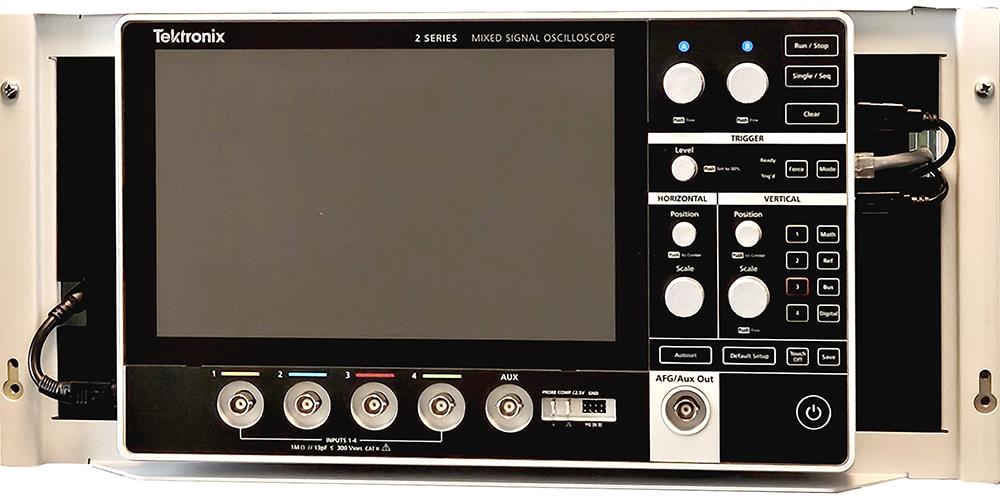
This document supports installing the 2 Series MSO with the rackmount kit in a standard equipment rack.
此手冊適用於:
MSO22, MSO24, 2-RK, MSO22-EDU, MSO24-EDU
相關產品資訊
下載即代表您同意 手冊下載協議的條款與條件。
手冊下載協議
注意:從此網站下載任何文件前,請先詳閱下列條款與條件。 若從 Tektronix 網站下載手冊,即表示您同意下列條款與條件:
目前支援之產品的手冊:
Tektronix 在此授予 Tektronix 儀器擁有人權限與授權,可在此網站下載和重製手冊,供內部或個人使用。 未經 Tektronix, Inc 特別書面授權,不得重製目前支援的產品手冊,並散佈給他人。
Tektronix 手冊可能經適當修訂,以反映製造過程中對產品所做的變更。 因此,任何現有產品可能具備不同版本的手冊。 請務必確保使用者取得特定產品序號的正確手冊版本。
不再支援之產品的手冊:
Tektronix 不提供已不再長期支援的量測產品手冊。 Tektronix 於此授權其他人重製和散佈任何 Tektronix 量測產品手冊副本的權限與授權,包括使用者手冊、操作員手冊、維修手冊等,該等手冊應 (a) 具備 Tektronix 零件編號,且 (b) 為 Tektronix 不再支援的量測產品手冊。
Tektronix 手冊可能經適當修訂,以反映製造過程中對產品所做的變更。 因此,任何現有產品可能具備不同版本的手冊。 請務必確保使用者取得特定產品序號的正確手冊版本。
此等權限與授權不適用於 Tektronix 目前仍支援的任何手冊或其他出版品,或視訊生產產品/彩色印表機產品的任何手冊或其他出版品。
免責聲明:
若量測產品手冊或其他出版品並非 Tektronix 提供,或並非依前述權限和授權製作或散佈,Tektronix 將不保證其資訊、文字、圖片、示意圖、零件清單或其他內含資料的準確度或完整性。
Tektronix 得逕行變更此網站內容或其產品,恕不另行通知。
責任限制:
若因使用依前述權限和授權製作或散佈的任何量測產品手冊或其他出版品,而導致任何損害 (包括但不限於:任何二次損壞或意外損壞、利益損失損害、營業中斷損害或違反智慧財產權損害),Tektronix 概不負責。
Read Online
Kit description
The 2-RK rackmount kit is a collection of parts that, once installed, configure the instrument for mounting into a standard 19-inch equipment rack.
This kit supports all 2 Series MSO instruments.
Parts list
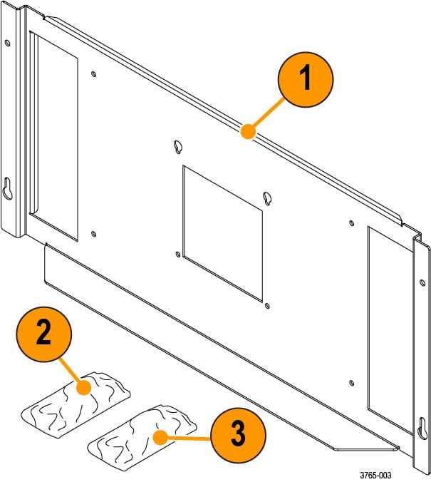
| Item | Part Number | Quantity | Description |
|---|---|---|---|
| 1 | 407-6248-XX | 1 | Rackmount bracket |
| 2 | 211-1732-XX | 8 | Screw, M4X.7X8mm. Use for attaching the bracket to the instrument. |
| 3 | 212-0577-XX | 4 | Screw, Machine 10-32x.625. Optional, use for attaching the instrument with bracket to the rack. |
Recommended installation tools
Use a screwdriver handle with No. 2 Phillips screw tip or a No. 2 Phillips screwdriver to install your rackmount kit.
Warranted characteristics
When the instrument is installed according to the instructions in this document, the rackmounted instrument meets all warranted requirements listed in the instrument specification. Instruments mounted using methods other than those described in these instructions might not meet their warranted requirements.
For tables of the warranted characteristics, see Specifications in the specification and performance verification manual that applies to your instrument model.
 | CAUTION:The rack is more susceptible to tipping when the instrument is installed. To prevent the rack from tipping, ensure that the rack is stable before accessing rear panel of the instrument. |
The ambient temperature inside the instrument rack will vary depending on the location of the instrument within the instrument rack. Tektronix recommends that you measure the ambient temperature in the desired rack location before you install the instrument to ensure the operating temperature does not exceed the rated ambient temperature limit. If necessary, refer to the Environmental Specifications in your product documentation for the operating temperature limits.
| CAUTION:The instrument might be damaged due to overheating. When installing multiple instruments in an instrument rack, the ambient temperature may go up. You assume the responsibility to provide adequate cooling to meet the ambient temperature requirements listed in the specifications. |
Clearance requirements
The rack in which the individual instrument is mounted must provide the following clearance requirements.
- At least 222 mm (8.75 in) of vertical space or 5 RU (rack units) of vertical space.
- A minimum inside depth of at least 14 mm (0.55 in) depth (from rack mounting ear to back of instrument).
- A minimum external clearance of at least 34 mm (1.34 in) frontwards from rack mounting ear.
- Airflow enters from underneath the instrument and exits at the top of the instrument. The rack mount bracket ensures clearance for adequate airflow.
- No additional clearance is needed on the left or right sides of the instrument for adequate airflow.
| CAUTION:Adhering to these requirements mounts the rack-adapted instrument with enough clearance for air circulation and accommodation of the power cord and mounting hardware. Failure to provide these clearances can result in overheating and can cause the instrument to operate improperly or fail. |
Install the rackmount on the instrument
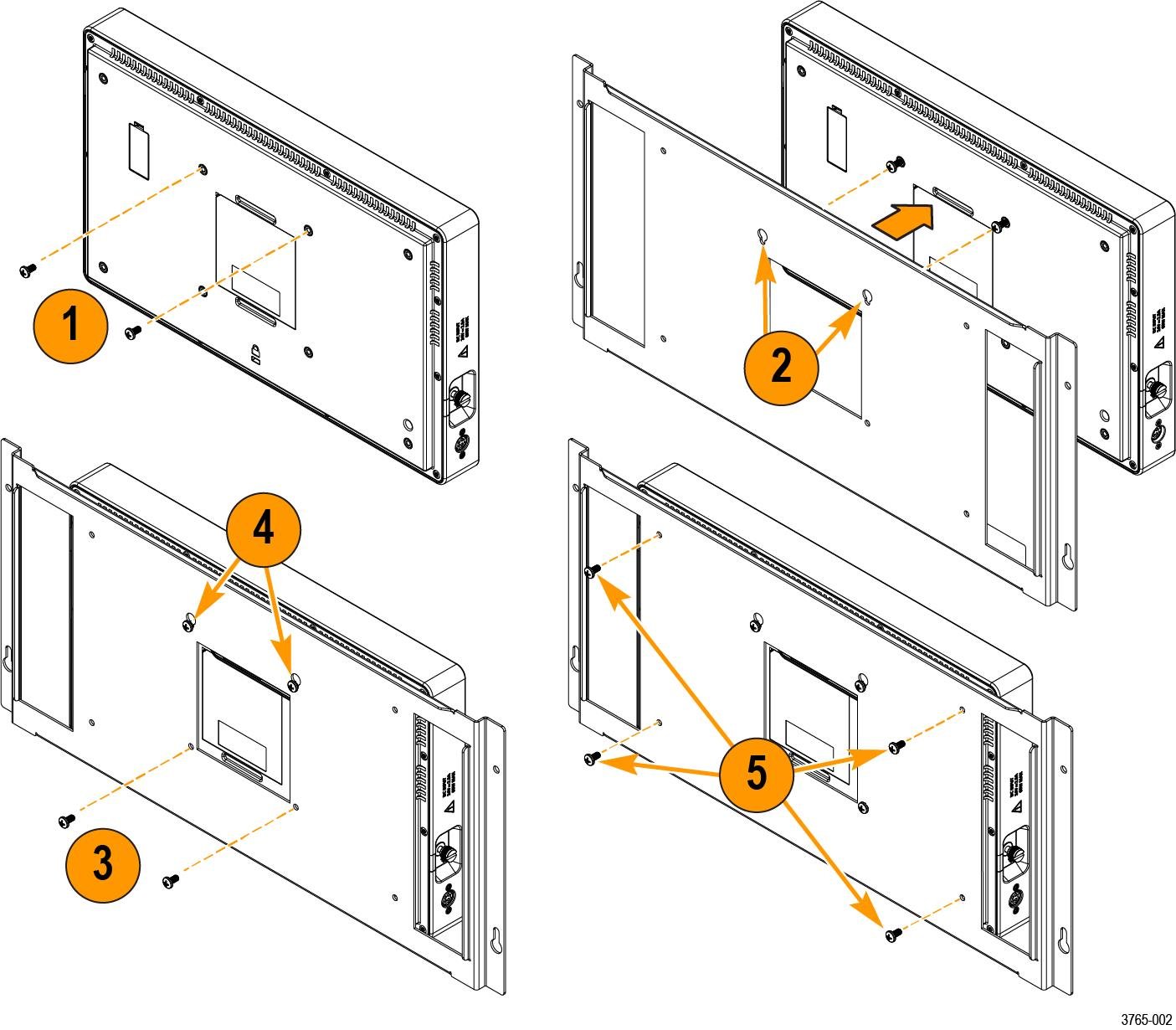
Install the 2-RK rackmount onto the back of your 2 Series MSO instrument using the following instructions.
Before you begin
These instructions are for qualified service personnel who are familiar with servicing the product. If you need further details for disassembling or reassembling the product, refer to the appropriate product manual. Contact your nearest Tektronix, Inc., Service Center or Tektronix Factory Service for installation assistance.
Procedure
Install the instrument into the rack
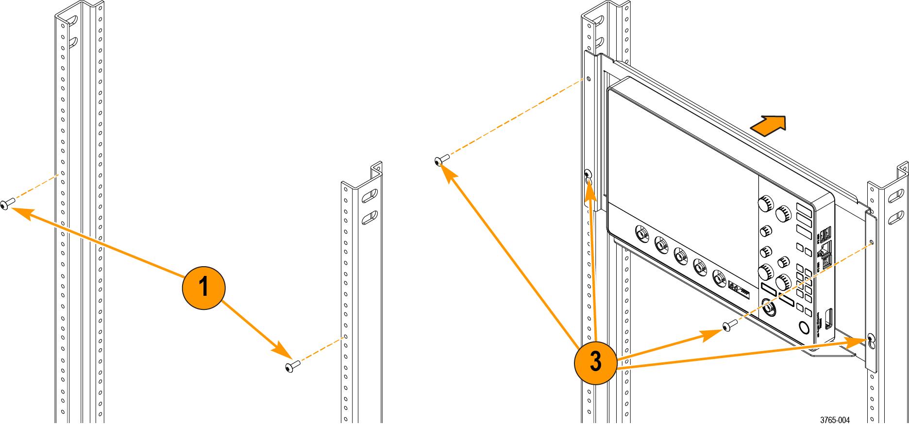
Install the 2 Series MSO instrument with the rackmount into your rack.
Before you begin
Procedure
What to do next
Dimensions
The dimensions of the rackmount installed on the instrument.
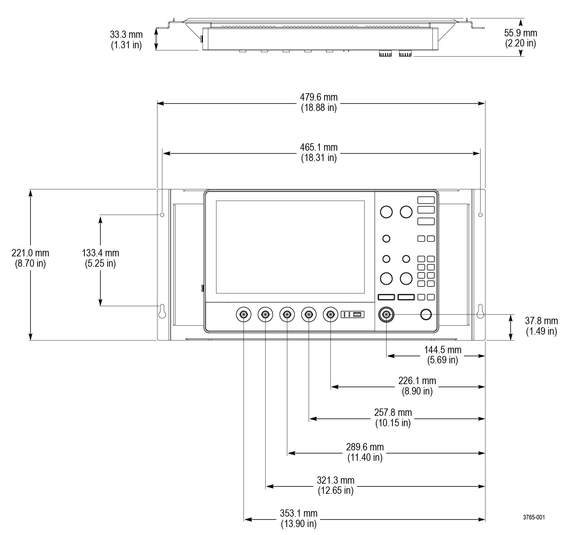
Install the optional side panels
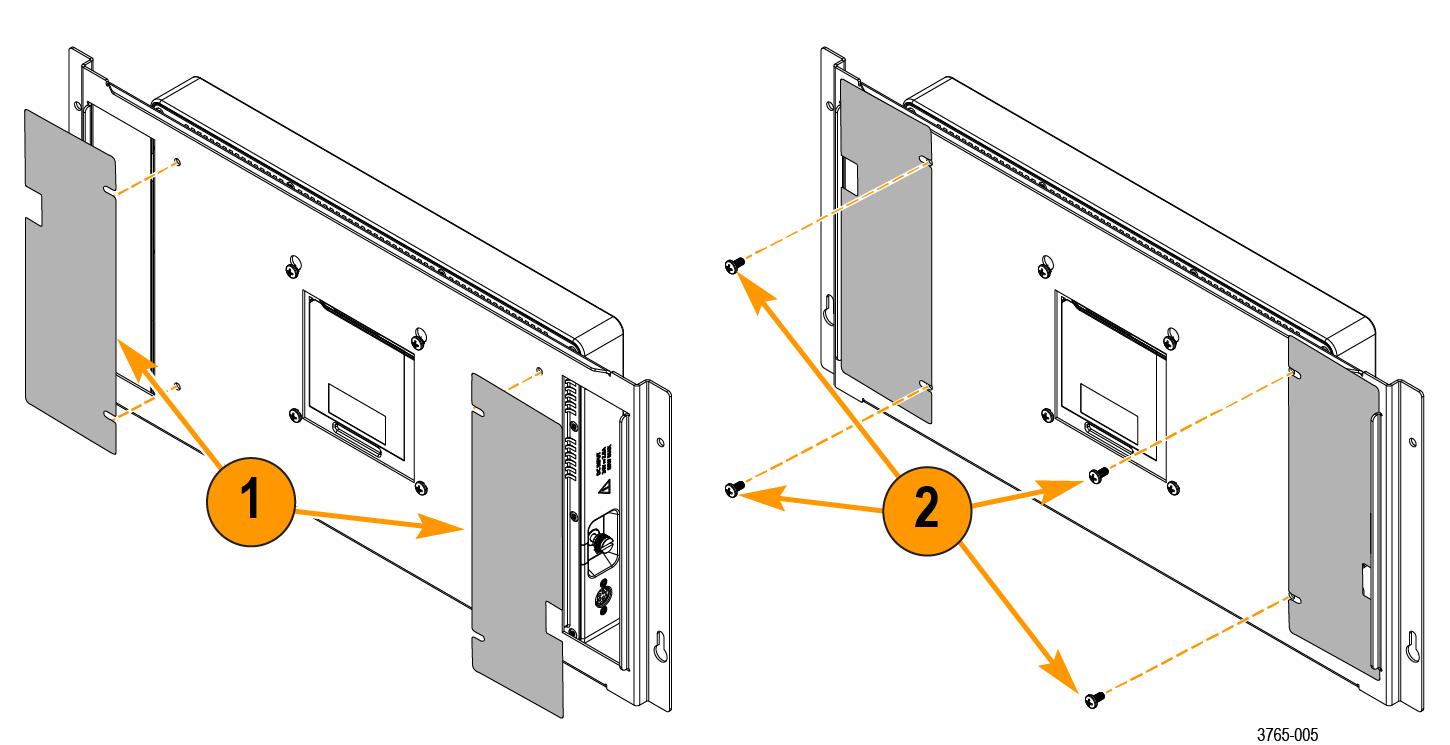
The following is an optional procedure to install optional side panels to the 2-RK rackmount to control airflow while still allowing cable connections to the instrument.
Before you begin
- Download the PDF version of this document at https://www.tek.com/manual/oscilloscope/2-rk-rackmount-kit-instructions-2-series-mso.
- Download the MSO2 RACK FILLER PANEL.STL file from the attachments in the PDF version.
- Use the geometry from the STL file produce the side panels using the additive manufacturing method (3D printing) and material of your choice.
- Create both side panels from the STL file. The panels are designed to be reversible.
- Remove the four outer rackmount screws and set them aside. The four screws will be used to secure the two side panels.
Procedure
Results