特定の作業に最適なオシロスコープをお探しではないですか?本記事では、熟練のエンジニア、学生、またはエレクトロニクス愛好家へ、ニーズに最も合ったオシロスコープを見つけるための明確なフレームワークを提供します。帯域幅、サンプル・レート、立ち上がり時間などの重要なパラメータを検討し、精度と効率を高めるための選択ができるようサポートします。用途別におすすめのオシロスコープもご紹介します。
オシロスコープの用途は?
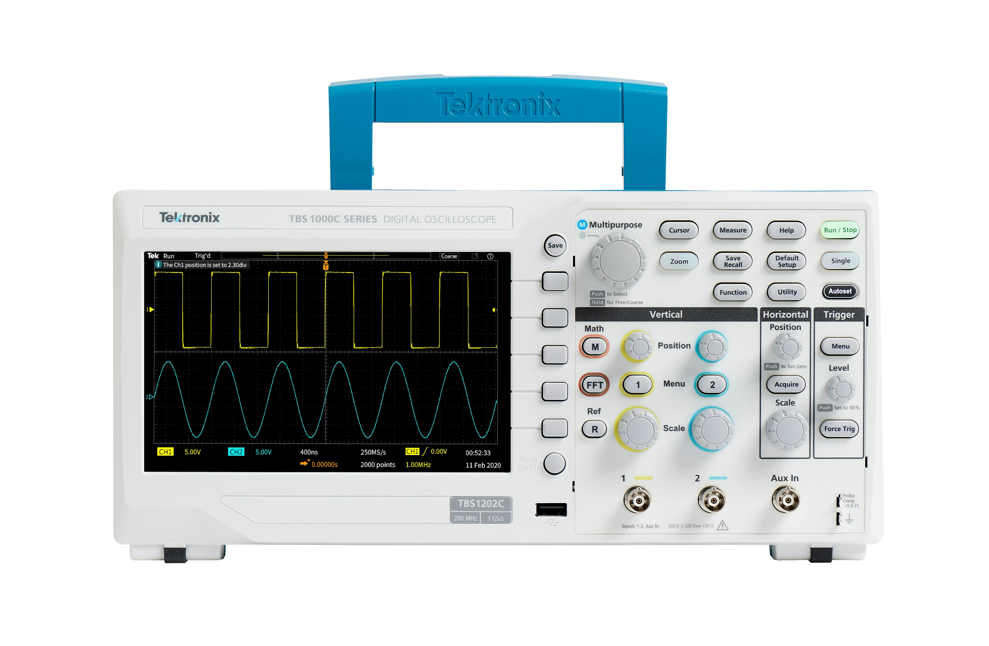
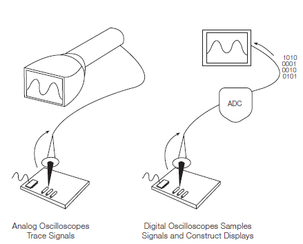
オシロスコープ (略称はオシロ、以前はオシログラフとして知られていました) は、電気信号をグラフィカルに表示し、それらの信号が時間とともにどのように変化するかを示す測定器です。 エンジニアは回路のトラブルシューティングや信号品質のチェックに使用します。多くのエンジニアはデジタル・オシロスコープを使用しており、本記事ではそのデジタル・オシロスコープに焦点を当てます。デジタル・オシロスコープは波形を取得して保存し、信号の電圧、周波数、信号間のタイミング、信号の一部がノイズであるか、信号が歪んでいるか、などを示します。
オシロスコープ選びに重要な基本要素
オシロスコープの周波数帯域
帯域幅は、オシロスコープが正確に測定できる最高周波数を決定する重要な仕様で、オシロスコープの機能性とコストの両方に影響を与える極めて重要な要素です。

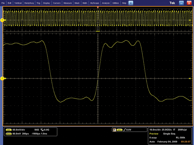
帯域幅が高いほど、信号の再現性が高くなります。例えば、250 MHz、1 GHz、4 GHzの帯域幅レベルでキャプチャされた信号を例にとって説明します。
必要な帯域幅の計算方法
オシロスコープを選ぶ際には、信号の最高周波数を確実にカバーするために、次の数式を使用します。
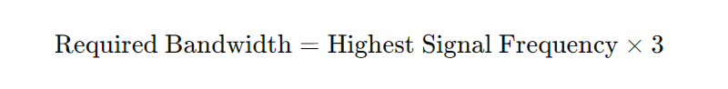
例えば、最高信号周波数が20 MHzの場合、少なくとも60 MHzの帯域幅を持つオシロスコープを検討するべきです。
立ち上がり時間
立ち上がり時間はデジタル用途において重要であり、信号の急激な変化を追跡する能力を示します。
高速デジタル信号の立ち上がり時間の特性評価
必要な立ち上がり時間の計算方法
オシロスコープの立ち上がり時間は、信号の最速の立ち上がり時間よりも大幅に短くなければなりません。適切なオシロスコープを見つけるために次の数式を使用します。
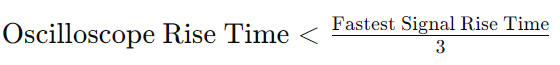
例えば、信号の立ち上がり時間が4 nsの場合、オシロスコープの立ち上がり時間は1.33 ns未満であるべきです。
オシロスコープのサンプル・レート
サンプル・レートは、オシロスコープが信号をどのくらいの頻度でサンプリングするかを示し、キャプチャされる波形の詳細に影響を与えます。
サンプル・レートが高いほど信号の解像度が高くなり、断続的なイベントも確認できます。
必要なサンプル・レートの計算方法
適切なサンプル・レートを計算するために、次の数式を使用します。
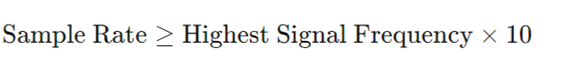
例えば、最高周波数が20 MHzの信号の場合、少なくとも200 MS/sのサンプル・レートを持つオシロスコープを選ぶべきです。そうすることで、波形が詳細にキャプチャされ、正確な分析が可能になります。
オシロスコープ選びのその他の考慮事項
チャンネル数
デジタル・オシロスコープはアナログ・チャンネルをサンプリングして保存し、表示します。一般的に、チャンネル数は多い方が良いですが、チャンネル数が増えるとオシロスコープの価格も上がります。
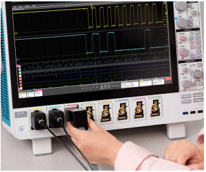
用途に応じて、2、4、6、または8つのアナログ・チャネルを持つオシロスコープを選ぶ必要があります。例えば、2チャンネルではコンポーネントの入力と出力を比較できます。4つのアナログ・チャンネルは、より多くの信号を比較でき、チャンネルを数式的に組み合わせる柔軟性を提供します(例:乗算して電力を求めたり、差分信号を求めるために減算ができる)。6または8チャネルのオシロスコープは、電力関連の環境で電圧や電流タイプの信号を同時に表示しながら、複数のバスを解析することができます。
ミックスド・シグナル・オシロスコープはデジタル・タイミング・チャンネルを追加し、ハイまたはローの状態を示し、バス波形として一緒に表示できます。どのチャンネル数を選ぶにしても、すべてのチャンネルが良好な範囲、直線性、ゲイン確度、平坦性を持ち、静電気放電に対する耐性を持っているべきです。
一部の機器は、コストを節約するためにチャネル間でサンプリング・システムを共有しています。しかし、その場合には注意が必要です。使用するチャネル数が増えるとサンプル・レートが低下する可能性があるからです。
対応プローブ
良い測定はプローブの先端から始まります。オシロスコープとプローブはシステムとして連携するため、オシロスコープを選ぶ際にはプローブも考慮する必要があります。
測定を行う際、プローブは実際に回路の一部となり、抵抗、静電容量、インダクタンスの負荷を引き起こし、測定値を変化させます。その影響を最小限に抑えるためには、オシロスコープと共に使用するように設計されたプローブを使用するのが最適です。
パッシブプローブを選ぶ際は、十分な帯域幅を持つものを選びましょう。プローブの帯域幅はオシロスコープの帯域幅に一致すべきです。
幅広い対応プローブがあることで、より多くの用途でオシロスコープを使用することができます。購入前に対応するプローブが何かを確認しましょう。
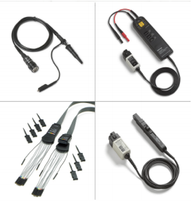
パッシブ・プローブ: 10倍減衰のプローブは回路に対して制御されたインピーダンスとキャパシタンスを提供し、ほとんどの接地基準測定に適しています。ほとんどのオシロスコープにはパッシブ・プローブが付属しており、各入力チャネルごとに1本必要です。
高電圧差動プローブ: 差動プローブは、接地基準のオシロスコープで安全かつ正確なフローティング測定および差動測定を行うことができます。各ラボには少なくとも1本は必要です。
ロジック・プローブ: ロジック・プローブはデジタル信号をミックスド・シグナル・オシロスコープのフロント・エンドに送ります。回路基板上の小さなテスト・ポイントに接続するためのアクセサリ付きの「フライングリード」を含みます。
電流プローブ: 電流プローブを追加すると、オシロスコープで電流を測定できるだけでなく、瞬時電力を計算して表示することもできます。
適切なプローブの選択に困っていませんか?「オシロスコープ・プローブの選び方」をご参考にご覧ください。
トリガ機能
すべてのオシロスコープはエッジ・トリガを提供し、多くのオシロスコープはパルス幅トリガも提供します。異常データを取得し、オシロスコープのレコード長を最大限に活用するためには、より困難な信号に対して高度なトリガを提供するオシロスコープを選ぶことが重要です。
トリガ・オプションの範囲が広いほど、オシロスコープの汎用性が高まり、問題の根本原因に迅速に到達できます。
- デジタル/パルストリガ: パルス幅、ラント・パルス、立ち上がり/立ち下がり時間、セットアップ・ホールド
- ロジック・トリガ: 複雑な論理条件に基づいたトリガ
- シリアル・トリガ: 組み込みシステム設計では、シリアル(I2C、SPI、CAN、LINなど)およびパラレルバスの両方を使用
- ビデオ・トリガ: ビデオ信号に基づいたトリガ
レコード長
レコード長とは、ひとつの波形レコードを構成するポイントの数を指します。オシロスコープは限られた数のサンプルしか保存できないため、一般的にレコード長が長いほど良いとされています。
記録時間= レコード長/サンプル・レート例えば、レコード長が1 Mポイントでサンプル・レートが250 MS/secの場合、オシロスコープは4 msをキャプチャします。今日のオシロスコープは、アプリケーションの詳細レベルに応じてレコード長を選択できるようになっています。
基本的なオシロスコープは2,000ポイント以上を保存でき、安定した正弦波信号(約500ポイント必要)には十分です。一方で、より高度なハイエンドオシロスコープは最大1Gポイントを持ち、高速シリアルデータ型アプリケーションで作業するためには不可欠です。
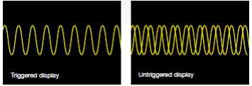
波形キャプチャ・レート(取込レート)
波形キャプチャ・レートは、1秒あたりの波形数(wfms/s)で表され、オシロスコープが波形を取得する速度を指します。オシロスコープの波形キャプチャ・レートは大きく異なるため、用途に合ったものを見つけることが重要です。
高い波形キャプチャ・レートを持つオシロスコープは、信号の動作に関する視覚的な洞察を大幅に向上させ、ジッタ、ラント・パルス、グリッチ、遷移エラーなどの一時的な異常を迅速にキャプチャする確率を劇的に高めます。
デジタル・ストレージ・オシロスコープ(DSO)は、10から5,000 wfms/sの範囲で波形をキャプチャするためにシリアル処理アーキテクチャを採用しています。DSOの中には、バースト的に多くの波形データを取込み、それを長いメモリに格納していく特別なモードを備えるものがありますが、一時的に高い波形取込レートが得られるように見えても、その後に続く長い処理時間(デッド・タイム)のために、発生頻度の低い間欠的現象を捉える確率は低下してしまいます。
多くのデジタル・フォスファ・オシロスコープ(DPO)は、並列処理アーキテクチャを採用し、非常に高い波形キャプチャ・レートを提供します。一部のDPOは数秒で数百万の波形を取得でき、間欠的で捉えにくいイベントをキャプチャする確率を大幅に高め、信号の問題をより迅速に見つけ出すことができます。
拡張性
ニーズの変化に対応するには、アプリケーションモジュールやソフトウェアアップデートに対応しているオシロスコープが必要になります。
時間とともにオシロスコープの機能を拡張したい場合は、必要なすべての機能が備わっていることを確認しましょう。例えば、一部のオシロスコープでは以下のことが可能です。
- チャンネルにメモリを追加して、より長いレコード長を解析
- アプリケーション固有の測定機能を追加
- フルレンジのプローブやモジュールでオシロスコープのパワーを補完
- 人気のサードパーティ解析および生産性向上ソフトウェアと連携
- Windows互換のソフトウェア
- バッテリ・パックやラックマウントなどのアクセサリを追加
接続性
オシロスコープの測定結果を解析した後、その結果を記録し共有する必要があります。オシロスコープの接続性は、先進的な解析機能を提供し、結果の記録と共有を簡素化します。
オシロスコープによっては、標準インターフェース(GPIB、RS-232、USB、Ethernet)、ネットワーク通信モジュール、または以下のような高度な機能が利用可能です。
- 特定の環境で機器を操作しながら、オシロスコープ上でドキュメントを作成、編集、および共有
- ネットワーク印刷およびファイル共有リソースへのアクセス
- Windows®デスクトップへのアクセス
- サードパーティの解析およびドキュメント作成ソフトウェアの実行
- ネットワークへの接続
- インターネットへのアクセス
- メールの送受信
オシロスコープ選びに悩んでいませんか?「オシロスコープ選定ガイド」をぜひご覧ください。製品デモのご依頼も可能です。すでにご希望のオシロスコープが決まっている場合は、製品ページからお買い求めください。