Contact us
Live Chat with Tek representatives. Available 6:00 AM - 4:30 PM
Call us at
Available 6:00 AM – 5:00 PM (PST) Business Days
Download
Download Manuals, Datasheets, Software and more:
Feedback
Jitter, Noise and Eye-diagram Analysis Solution
DPOJET Datasheet
More Information
- Máy hiện sóng tín hiệu hỗn hợp MSO/DPO5000B
- Máy hiện sóng lân quang số/tín hiệu hỗn hợp MSO/DPO70000DX
- DPO7000
- Máy hiện sóng hiệu suất DPO70000SX ATI
- Explore more Phần mềm models
Read Online:
DPOJET is the premier eye-diagram, jitter, noise and timing analysis package available for real-time oscilloscopes. DPOJET provides the highest sensitivity and accuracy available in real-time instruments. With comprehensive jitter and eye-diagram analysis and decomposition algorithms DPOJET simplifies discovering signal integrity concerns and jitter and their related sources in today's high-speed serial, digital, and communication system designs. Analysis options scale from timing (standard), to jitter (opt. DJA) and noise (opt. DJAN) analysis.
Key standard features
- Period, frequency, and time interval error analysis
- Timing parametrics such as rise/fall times, pulse width, and duty cycle
- Many graphical tools such as Histograms, Time Trends, and Spectrums
- Programmable software clock recovery including software PLL 1
- User-selectable golden PLL support for popular standards
- Automatic bit rate and pattern length detection eases measurement configuration
- Selectable high- and low-limit measurement bounds test
- Comprehensive statistics logging, reporting, and remote automation
- Capture and save worst-case signals for detailed analysis
- TekWizard™ interface for one-button and guided jitter summaries
- DPOJET Essentials is standard on all DPO/DSA/MSO70000, DPO7000, and MSO/DPO5000 Series oscilloscopes
- Optical signal analysis capability
- Relative mask support for optical signal
- RJ Lock allows measurements analysis at specific random jitter value
- Eye diagram rendering using interpolation and non interpolation technique
- Higher order clock recovery for PCIE Gen5
Key features of Jitter Analysis (Opt. DJA)
- Jitter and Timing Analysis for analog and digital clocks and data signals
- Real-time Eye-diagram (RT-Eye®) Analysis 2
- Selectable high- and low-pass measurement filters
- Ten plot types to view and analyze jitter: Eye Diagram, CDF Bathtub, Spectrum, Histogram, Composite Histogram, Trend, Data, Phase Noise, and Transfer Function
- Accurate jitter analysis using the spectral and Q-scale methods for detailed decomposition of jitter components, including the extraction of industry standard dual-dirac model parameters
- Jitter separation algorithms accurately measure the effects of bounded uncorrelated jitter (BUJ) which enables precise TJ measurements
- Full pass/fail limits and mask testing with comprehensive standards support library; plus user limit and mask files allow support of custom test configurations and new or developing standards
- DPOJET Advanced is standard on DSA/MSO70000 Series, optional on DPO70000, DPO7000, and MSO/DPO5000 Series oscilloscopes
- Optical signal analysis support
- Relative mask support for optical signal
- Eye diagram rendering using interpolation and non interpolation technique
Key features of Noise Analysis (Opt. DJAN)
- Decomposition of noise components models system performance at a target bit error ratio
- Understand the source of jitter and noise through measurements that report the contribution of jitter to noise and noise to jitter
- View the eye opening at selected bit error ratios with BER contour plots
- Probability mapping of events at a specific voltage/timing position
- Visualize the impact of unbounded noise on eye height across BER levels
- Correlated eye analysis enables analysis of the effect of equalization on correlated jitter
- Scope noise compensation removes the effects of scope vertical noise from measurement results improving accuracy and device margin.
Applications
- Characterize performance of high-speed serial and parallel bus designs
- Characterize clock and data jitter/noise and signal integrity
- Characterize PLL dynamic performance
- Characterize modulation of spread spectrum clock circuits
- Characterize jitter generation, transfer, and tolerance
Perform PHY testing of PCI Express, Serial ATA, SAS, Fibre Channel, MIPI® D-PHY, MIPI® M-PHY, DisplayPort, Thunderbolt, MHL, DDR, DDR2, DDR3, LPDDR, LPDDR2, SD UHS-II, MOST50, MOST150, USB 3.0, 10GBASE-KR/KR4, SFF-8431 SFP+ / 10GSFP+ Direct Attach Cable, and other electrical and optical systems
Realtime jitter, noise and eye-diagram analysis
DPOJET is the premiere eye-diagram, jitter, noise, and timing analysis package available for real-time oscilloscopes. Operating in the Tektronix DPO/DSA/MSO70000, DPO7000, and MSO/DPO5000 Series oscilloscopes, DPOJET provides engineers the highest sensitivity and accuracy available in real-time instruments. With comprehensive jitter and eye-diagram analysis and decomposition algorithms DPOJET simplifies discovering signal integrity concerns and jitter and their related sources in today's high-speed serial, digital, and communication system designs.
Analog and digital designers in the computer, semiconductor, and communications industries are facing new challenges as processor clock speeds race beyond 3 GHz and back-plane bus and serial link data rates exceed 8 GT/s. These increasing speeds mean reduced circuit tolerance, or margin, for jitter and related signal integrity problems. By using tools that help you rapidly characterize and discover sources of jitter and signal integrity concerns, you can bring new designs to market faster, with more confidence that they operate reliably in today's ultra high-speed environment.
| Measurement | DPOJET Essentials | DPOJET Advanced | DPOJET Advanced Plus |
|---|---|---|---|
| Period/Frequency Measurements | |||
| Frequency 3, Period 3, N-Period, Cycle-Cycle Period, Positive Width 3 , Negative Width 3, Positive Duty Cycle 3, Negative Duty Cycle 3, Positive Cycle-Cycle Duty 3, Negative Cycle-Cycle Duty 3 | X | X | X |
| Time Measurements | |||
| Rise Time, Fall Time, Skew 3, High Time, Low Time, Setup 3, Hold 3, SSC Profile, SSC Modulation Rate, SSC Frequency Deviation, SSC Frequency Deviation Min, SSC Frequency Deviation Max, Time Outside Level, tCMD-CMD | X | X | X |
| Rise Slew Rate, Fall Slew Rate | X | X | |
| Amplitude Measurements | |||
| High, Low, High-Low, AC Common Mode, DC Common Mode, Overshoot, Undershoot, Cycle Min, Cycle Max, Cycle Pk-Pk, Common Mode, T/nT Ratio, Differential Crossover, AC RMS | X | X | |
| Jitter Measurements | |||
| TIE, Phase Noise | X | X | X |
| TJ@BER, DJ, DDJ, PJ, DJ-dd, DCD, RJ, RJ-dd, SRJ, F/N, J2, J9, PJrms, SJ@Freq, PkPkClkTJ, PKPKClkRJ, PkPKClkDJ, Clock NPJ | X | X | |
| Eye-diagram Measurements | |||
| Width, Height, Mask Hits, Width@BER, Eye High, Eye Low, Height@BER, Q-Factor, AutoFitMaskHits, DFE_EW, DFE_EH, DFE_EyeDiagram, V-Widest Open Eye | X | X | |
| Optical Measurements | |||
| AOP, OMA, Optical High, Optical Low, ER, Eye Crossing Level, Eye Crossing Time, Eye Crossing Percentage, Mask Margin, Mask Hit Ratio, TDEC, RIN and RINxOMA. | X | X | |
| Noise Measurements | |||
| TN@BER, RN, RN(v), RN(h), DN, DDN, DDN(0), DDN(1), PN, PN(v), PN(h), Unit Amplitude | X | ||
| Noise Plots: Composite Noise Histogram, Noise Bathtub, BER Eye Contour, PDF Eye, BER Eye, Correlated Eye | X | ||
| Clock Recovery Methods | |||
| Constant Clock Mean, Constant Clock Median, Constant Clock Fixed, Explicit Clock Edge, Explicit Clock PLL, Type I PLL, Type II PLL | X | X | X |
| Plots | |||
| Histogram, Time Trend, Data Array, Spectrum, Phase Noise, Transfer Curve | X | X | X |
| Eye Diagram, Waveform (Mask Hit correlation), Bathtub, Composite Histogram | X | X | |
| Limit and Mask Testing | |||
| Pass/Fail Measurement Test Limits, Load and Test to Standard Masks | X | X | |
| Data Logging | |||
| Measurements, Statistics, Worst-case Waveform, and Snapshots | X | X | X |
| Report Generation | |||
| Export HTML/PDF Formatted Reports with Summary, Statistics, and Plots | X | X | X |
| Pass/Fail Status | X | X | |

DPOJET Jitter and Eye-diagram Analysis Tools extend the capability of Tektronix real-time oscilloscopes, performing complex measurements and analysis of clock, serial, and parallel data signals captured in Single-shot Acquisition mode or in Continuous-run Acquisition mode. Measurements in DPOJET are supported on either analog or digital channels as shown in the measurement table. Providing jitter and timing measurements with pass/fail parameter testing, and eye diagrams with mask testing for today’s most common industry standards, DPOJET is specifically designed to meet the advanced measurement needs of today's high-speed digital designers in the computer and communications industries.
As data rates increase, next generation interfaces present new test and measurement challenges, including the need to measure and isolate sources of BUJ (for example crosstalk). Crosstalk can be caused due to the coupling of energy on the lane under test from adjacent lanes.
While Receiver and Transmitter Equalization can compensate for data dependent jitter (DDJ), crosstalk effects are difficult to remove. This has resulted in many standards, for example Thunderbolt, including BUJ in the jitter budget making BUJ a required measurement.
DPOJET provides support for both legacy and BUJ jitter separation algorithms as shown in Figure 1. When using the BUJ Jitter Decomposition method, the NPJ measurement is available in the Jitter tab within DPOJET.
Noise analysis with DPOJET (Opt. DJAN)
In the past, users have relied on jitter measurements and visualization to understand the behavior of their device under test. The test methodologies defined by many of the standard bodies have largely been concerned with the impact of jitter on horizontal eye closure. As data rates increase, the eye that is being analyzed has become smaller and smaller, making analysis of both vertical and horizontal eye closure a requirement. Understanding both the impact of jitter and noise enables engineers to predict the overall eye opening at a target bit error ratio. Traditional jitter and noise measurements provide analysis at a single sampling point, a BER contour can show much more about the overall behavior of a system. In the plot below, the user can quickly visualize the eye opening at many different target bit error ratios. As expected the more vertical closure as the BER increases, the more random noise is in the system. The same is true for random jitter in the horizontal direction.

Jitter and Noise bathtub plots are also useful in visualizing the effects of jitter and noise on eye closure. These plots represent a single sampling point as configured in the jitter and noise measurements.

With the reliance on transmitter and receiver equalization in many of today's high speed serial standards, it is also useful to visualize the effects of the equalization on the eye diagram. Equalization is good at compensating for data dependent jitter that may be caused due to the effects of the channel. When observing an acquired eye diagram, the eye diagram is composed of the entire population in the acquisition. This can make it difficult to visualize the composition of the eye due to data dependent jitter.
The eye diagrams below illustrate the correlated eye of a signal before a channel, after a channel, and after equalization. We expect that the correlated eye will have more eye closure after the channel and that the correlated eye width after the equalization would closely match the acquired eye width prior to the channel if the equalizer is effectively compensating for the data dependent jitter. In this case the eye widths are within ~3ps as shown in the eye diagram on the left and right hand sides.

Optical signal analysis
Traditionally, sampling oscilloscope is the tool of choice for viewing and measuring optical signals. It provides many benefits in measuring optical signals with low noise/jitter and various measurement features optimized to characterize the optical signals.Real-time oscilloscopes are preferred for ample debug/troubleshooting and to capture intermittent single-shot events with deep memory and fast sample rates. Optical standards specify transmitter output performance in terms of eye mask definitions which are given in the terms of normalized amplitude and time.
The DPO7OE Series optical probe enables analysis of optical signal on real time oscilloscopes. These measurements include average optical power, extinction ratio, optical high, optical low, optical modulation amplitude, eye crossing time, eye crossing level, eye crossing percentage, mask margin and mask hit ratio.

Mask hits and Autofit mask hits measurement supports both absolute and relative mask.

Debug, Characterization, and Compliance
DPOJET is the only Jitter, Noise and Eye Analysis software that enables multi-source analysis with configuration flexibility on a measurement by measurement basis providing the ultimate debug, characterization, and compliance environment.
Multi-Lane Analysis
With other jitter, noise and eye analysis software solutions, analyzing multiple lanes is a painstaking process requiring multiple acquisitions to analyze each lane individually. DPOJET provides the capability to perform multiple measurements simultaneously on multiple sources, for example Ch1, Ch2, Ch3, and Ch4 enabling multi-lane analysis. Multiple lanes of traffic can be measured simultaneously allowing faster analysis and easy comparison of results for multi-lane standards including PCI Express, HDMI, and DisplayPort. This makes it easy to do visual comparison between the lanes and quickly note differences in signal quality parameters, for example noise, jitter, rise time, fall time, and amplitude between the lanes. Also available is DPOJET Reports which allows the generation of a html report which contains instrument and measurement configuration details, measurement results, and plots. 
Multi-Source Analysis
Building upon the ability to perform the same measurement simultaneously multiple times, DPOJET provides an environment that is well suited for analyzing the effects of post-processing actions, for example de-embedding, embedding, and equalization. Together with SDLA Visualizer, DPOJET provides the analysis environment which allows simultaneous measurements on the signal and different test points within the link. For example, a comparison between the acquired waveform and the waveform after de-embedding can be quickly done providing the details needed to validate the effects of de-embedding on the acquired signal. 
Multi-Measurement Configuration
Most high speed serial standards specify a reference phased locked loop (PLL) to use for clock recovery. This ensures that during the testing process that devices are all tested to the same standard. These PLLs are defined to filter or track the effects of low frequency jitter such as jitter due to Spread Spectrum Clocking (SSC). When using a PLL configuration that can track SSC, the SSC is attenuated and the result is a more open eye diagram. Typically, a 2nd order PLL is used to track the effects of SSC due to the ability to attenuate low frequency jitter. In cases where it is desired to see the effects of SSC constant clock recovery can be used which will not track the effects of SSC. Oftentimes, it is desired to see the effects of jitter, like SSC while at the same time evaluating the eye after using the reference PLL. This can quickly be done using the flexible measurement configuration feature in DPOJET. Measurements can be configured to all use the same clock recovery technique or individual measurements can be configured using different clock recovery methods. 
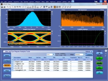
In other cases, it is desired to see the results in the frequency domain. DPOJET provides a spectral plot which shows the spectral content of the signal after clock recovery. The spectral content of the signal can quickly be compared after applying a 2nd order pll versus using constant clock recovery as shown in the image above.
Data Visualization
DPOJET supports displaying measurement results and plots on the internal display, on an external monitor, or both locations, thus making full use of the oscilloscope dual display ports.
DPOJET provides a rich set of interactive plots that enable analysis beyond what is possible with static plot images. Interactive features include zoom, pan, cursors, and finding the min and max values. For example, when looking at the spectral plot it is easy to find the frequency with the highest amplitude by using the Max cursor feature. The plot readout will then show the frequency and the amplitude of jitter.
DPOJET analysis plots, like Spectrum and Trend, go beyond simple measurements and results display. Trend analysis quickly shows engineers how timing parameters change over time, like frequency drift, PLL startup transients, or a circuit’s response to power supply changes. Spectrum analysis quickly shows the precise frequency and amplitude of jitter and modulation sources for easy, rapid identification. Finding sources like adjacent oscillators and clocks, power supply noise, or signal crosstalk is no longer a tedious chore. Unique in the industry, DPOJET also provides Phase Noise plots to show jitter in root/Hertz and Transfer Function plots that allow direct comparison of jitter spectrums between two signals of differing frequencies, providing the perfect tool for determining jitter in PLL circuits like clock multipliers. The composite histogram plot shows further details into the jitter components and their distribution in the data set. 

Once all measurements are completed, the user has the flexibility to generate a test report which includes the instrument configuration, probe configuration, measurement results with pass fail status, measurement configuration details, and any plots that were generated. Alternatively, the user also has the flexibility to generate a .csv file that contains the results. 
Ordering information
Model
- DPOJET Jitter Analysis and DPOJET Noise Analysis
Options
- Opt. DJA
- Order preinstalled on a new oscilloscope
- Opt. DJAN
Order preinstalled on a new oscilloscope, requires option DJA
Upgrades
Order an upgrade for existing oscilloscope:
- DPO-UP Opt. DJAE
- MSO/DPO5000 Series
- DPO-UP Opt. DJAM
- DPO7000 Series
- DPO-UP Opt. DJAH
- DPO/MSO70000 Series, 4-8 GHz
- DPO-UP Opt. DJAN
- DPO/MSO70000, DPO7000, MSO/DPO5000 Series
- DPO-UP Opt. DJAU
- DPO/MSO70000 Series, >12 GHz
- DPOFL-DJA
- Floating License
- DPOFL-DJAN
- Floating License, requires option DJA
Physical characteristics
Software is supplied on internal hard disk and on compact disk media, or can be downloaded from www.tektronix.com. Software installs and operates with DPO/DSA/MSO70000, DPO7000, or MSO/DPO5000 Series oscilloscopes. Online documentation and printable manual in PDF format are supplied with the product.
Recommended accessories
- Opt. 10G-KR
Ethernet 10GBASE-KR/KR4 Compliance and Debug Solution
- Opt. D-PHY
- MIPI® D-PHY Essentials
- Opt. DDRA
- DDR Memory Bus Analysis
- Opt. eDP
Embedded DisplayPort Essentials
- Opt. FC-16G
- Fibrechannel Essentials
- Opt. MOST
MOST Essentials Electrical Compliance and Debug Test Solution for MOST50
- Opt. M-PHY
- MIPI® M-PHY Essentials
- Opt. PCE
- PCI Express® Measurements for DPOJET
- Opt. PCE3
PCI Express Gen 3 (includes opt. PCE) Measurements for DPOJET
- Opt. SAS3
- SAS Essentials
- Opt. SFP-TX
- Ethernet SFP+ Compliance and Debug Solution
- Opt. SSP
- SuperSpeed Plus Essentials
- Opt. UHS2
- SDA UHS-II DPOJET Essentials
- Opt. USB3
- USB 3.0 Tx Essentials. Requires Opt. DJA and ≥8 GHz oscilloscope.
1 Patented USPTO #6,812,688.
2 Patented USPTO #6,836,738
3 Available on MSO digital channels

Tektronix is ISO 14001:2015 and ISO 9001:2015 certified by DEKRA. Product(s) complies with IEEE Standard 488.1-1987, RS-232-C, and with Tektronix Standard Codes and Formats. 61W-21170-14

