

與我們聯絡
與 Tek 業務代表即時對談。 上班時間:上午 6:00 - 下午 4:30 (太平洋時間)
請致電
與 Tek 業務代表即時對談。 上班時間:上午 8:30 - 下午 5:30 (太平洋時間)
下載
下載手冊、產品規格表、軟體等等:
意見回饋
1 Series DPO
Overview
All the essentials and more
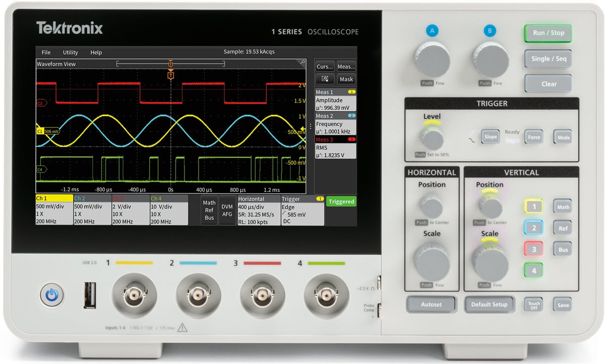
The 1 Series DPO features up to 4 analog channels, 200 MHz bandwidth, 1.25 GS/s sample rate, optional 25 MHz Arbitrary Function Generator (AFG), frequency counter, digital voltmeter, advanced triggers, and protocol decode, all in a compact form factor. The 1 Series DPO has all the essentials you need to learn and work.
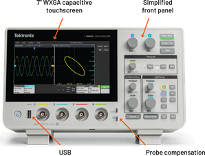
With a capacitive touchscreen and a highly intuitive user interface truly designed for touch, the 1 Series DPO completes the Tektronix family of oscilloscopes with its shared user interface and programmatic interface. This makes it even easier to use any Tektronix next generation oscilloscope.
A large catalog of compatible probes and accessories extend the 1 Series DPO capabilities and versatility to make it suitable for a variety of applications.
Key performance specifications
Analog input channels
2 or 4 inputs
Bandwidth
50 MHz, 70 MHz, 100 MHz, 200 MHz
Sample rate
1.25 GS/s half channels
625 MS/s all channels
Waveform capture rate
Up to 125 kwfm/s
Record length
10 Mpoints per channel
Vertical resolution
12-bit ADC
Standard trigger types
Edge, pulse width, runt, timeout, and rise/fall time
Standard analysis
Cursors: Waveform, V bars, H bars, and V&H barsMeasurements: 23Plots: XY, limit maskMath: Basic waveform arithmetic, FFT, and advanced equation editor
Serial trigger, decode and analysis
I
Additional features
5-digit digital voltmeter
6-digit frequency counter
Arbitrary function generator (S models only)
25 MHz waveform generator
Waveform types: Arbitrary, sine, square, pulse, ramp, DC level, and random noiseWaveform modulation: AM, FM, ASK, FSK, Sweep
Display
7-inch color display
Capacitive touchscreen
WSVGA 1024 × 600 resolution
Connectivity
USB 2.0 device (one port)
USB 2.0 host (one port)
LAN (10/100 BASE-T ethernet)
Remote control
Remotely view and control the oscilloscope over a network connection through eScope
VESA mount
100 mm × 100 mm VESA interface
Security
Kensington-style security slot
EUCRA compliant
Standard probes
One P2101 100 MHz, 1X/10X voltage probe per channel (50 MHz, 70 MHz, and 100 MHz bandwidth models)
One P2201 200 MHz, 1X/10X voltage probe per channel (200 MHz bandwidth model)
Collaborative tools (optional)
Optional accessories
Soft carrying case
Rackmount kit
Hard case
Warranty
One year standard
Tektronix next generation oscilloscopes
| ||||||
|---|---|---|---|---|---|---|
1 Series DPO | 2 Series MSO | 3 Series MDO | 4 Series B MSO | 5 Series B MSO | 6 Series B MSO | 7 Series DPO |
Small footprint with all the essentials | Compact, portable, battery | Extreme versatility for any bench — includes a spectrum analyzer | Up to 6 analog channels of high | Up to 8 analog and/or 64 digital channels of advanced analysis | Unmatched detail on high-speed signals | Unparalleled signal fidelity |

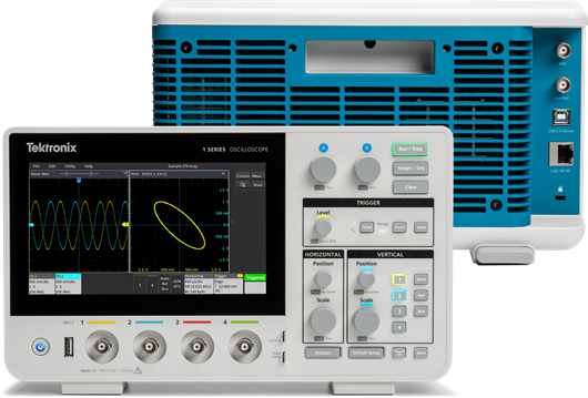
Easy touchscreen with simplified front panel
The 1 Series DPO offers the same interface as the higher
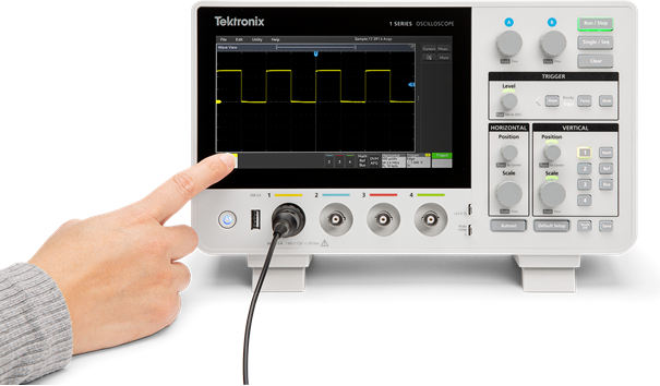
Drag waveforms left/right or up/down to adjust horizontal and vertical position or to pan a zoomed view.
Swipe in from the right to reveal the results bar or down from the top to access the menus in the upper left corner of the display.
The simplified front panel retains critical buttons and knobs with color-coded LEDs, allowing quick access and easy adjustment of the most frequently used instrument settings.
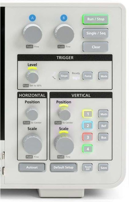
The combination of a streamlined front panel with an intuitive touch interface makes it easy for any new engineer to self
Work smarter with the intuitive UI
The user interface on the 1 Series DPO is designed for touch operation. All the key information is presented as a series of badges with visual cues. Get immediate access to instrument configuration or waveform management tasks with a single tap. A USB mouse is also supported and can be used as an interaction method with the instrument.
The 1 Series DPO offers a comprehensive set of standard analysis tools including:
Waveform and screen-based cursors with user-selectable readout location.
Common automated measurements with measurement statistics and gating.
Basic and advanced waveform math, including arbitrary equation editing.
Basic FFT analysis with options to view magnitude and options to customize window type and units. Works simultaneously across all analog channels.
The 1 Series DPO screen also displays plots, measurement results tables, bus decode tables, and more. You can easily resize and relocate the views to suit your needs.
Triggering
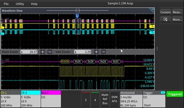
Discovering a device fault is only the first step. Next, you must capture the event of interest to identify the root cause. The 1 Series DPO provides a complete set of advanced triggers, including runt, pulse width, timeout, rise/fall time, and serial packet data, that can be used to capture complex infrequent events.
Limit mask testing
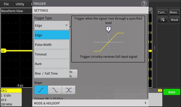
Limit mask testing offers a good way to test the quality of a signal. A mask can be defined based on a golden signal with user
The 1 Series DPO provides a comprehensive set of mask tools that allow you to:
Define test duration in number of waveforms
Set a violation threshold that must be met before considering a test failure
Count violations and failures and report statistical information
Serial protocol triggering and analysis
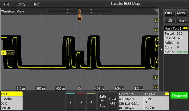
The 1 Series DPO offers a robust set of tools for working with serial buses found in embedded design, including I
The protocol decode and triggering capability is invaluable for tracing the flow of activity through a system by observing the traffic on a serial bus.
Serial protocol triggering lets you trigger on specific packet content, including start of packet, specific addresses, specific data content, unique identifiers, and errors.
Bus waveforms provide a higher-level, combined view of the individual signals of your bus, such as clock, data, and chip enable. This makes it easy to identify where packets begin and end and identify sub-packet components such as address, data, identifier, and CRC.
The bus waveform is time-aligned with all other displayed signals, making it easy to measure timing relationships across various parts of the system under test.
The bus decode table provides a tabular view of all decoded packets in an acquisition. Packets are timestamped and listed consecutively with columns for each component, such as address and data.
Arbitrary function generator (S models only)
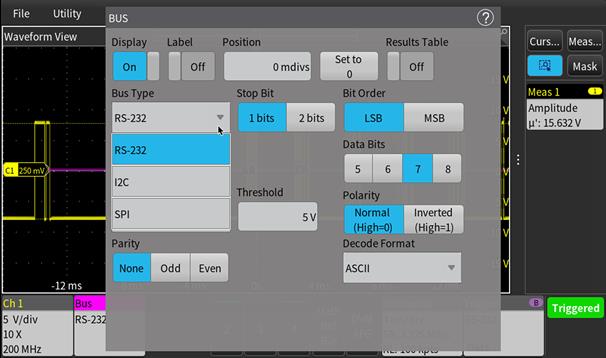
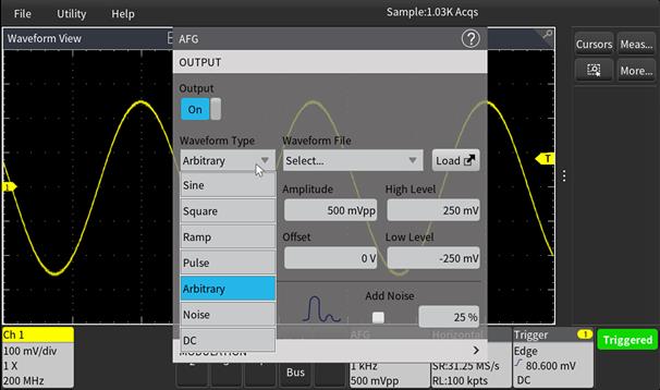
The 1 Series DPO (S models only) includes a 25 MHz arbitrary function generator (AFG) for creating signals in a design or adding noise to signals to perform margin testing.
Several predefined waveforms, including sine, square, pulse, ramp/triangle, DC, and noise, are included. In addition, the AFG also provides waveform modulation capability, including AM, FM, ASK, FSK, and Sweep.
The arbitrary waveform generator provides the ability to load saved waveforms from the analog input to replay on the AFG.
Connectivity
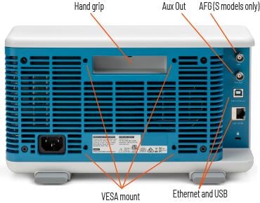
The 1 Series DPO contains several ports that you can use to connect the instrument to a network, directly to a PC, or to other test equipment.
USB 2.0 host port on the front of the instrument enables easy transfer of screenshots, instrument settings, and waveform data to a USB mass storage device. A USB mouse can also be attached for instrument control.
The USB device port allows you to control the oscilloscope remotely from a PC using an automation script through programmatic interface commands.
The standard 10/100BASE-T ethernet port enables easy connection to networks and remote control of the instrument. It also enables you to view the acquired data through eScope or an automation script through programmatic interface commands.
Bode plot (S models only)
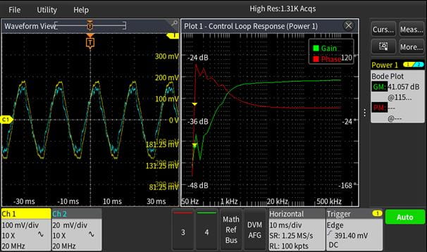
Analyze the frequency response of a system using the built-in Bode plot feature. The input voltage is swept across the user
|
|
Enhanced security
The 1 Series DPO offers:
Security slot that is compatible with Kensington
style locks to physically anchor the instrument. TekSecure Erase function to erase all user
specific data and set all settings to default values. Network Security that can turn off the ethernet port and provide eScope access that is password protected.
Compliance with EUCRA.
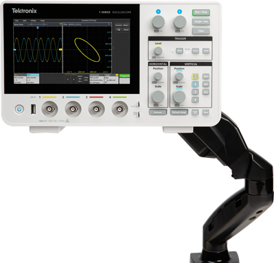
VESA mount
The 1 Series DPO has an industry standard VESA mount that is compatible with off-the-shelf accessories.
Accessories
Several accessories are available for use with the 1 Series DPO:
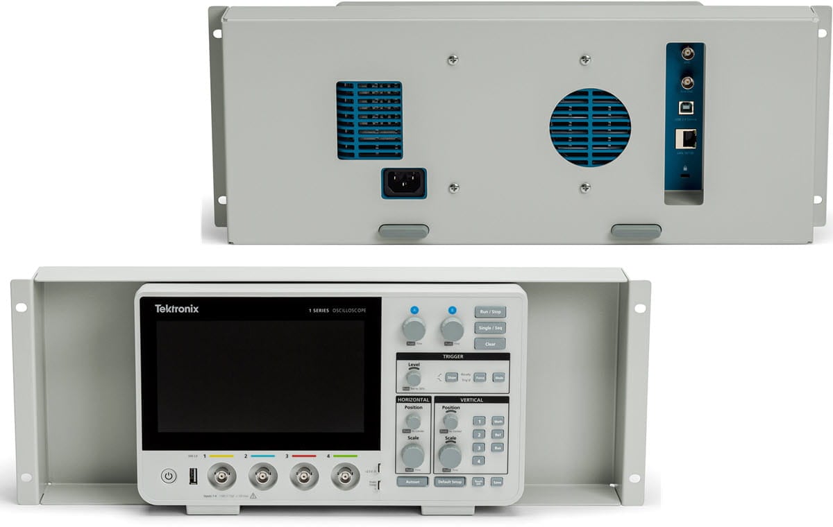
Install the instrument in a rack for production with the rackmount kit.
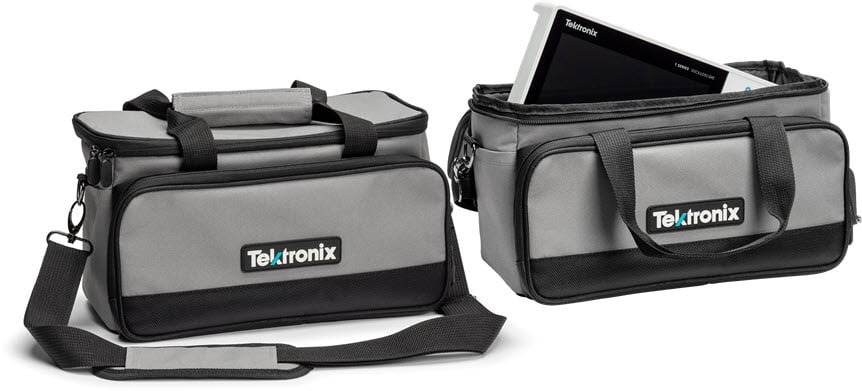
Carry the instrument into the field using the soft case.
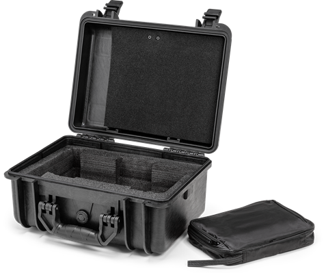
Provide additional protection when shipping with the hard case, which comes with foam inserts.
The 100 mm × 100 mm standard VESA interface on the back of the instrument is compatible with a wide variety of commercial accessories.
Programmatic interface
Programmable interface commands can be used to remotely control the instrument through the USB device port or the ethernet port. This enables programming the instrument to perform an automated set of tasks or integrating into a larger system that includes other equipment for performing specific tasks.
eScope
To use the eScope feature, simply connect the oscilloscope to a network using the ethernet port on the oscilloscope. Enter the scope’s IP address into a web browser and select the eScope instrument control panel from the home screen.
An exact replica of the oscilloscope’s screen appears on the browser. Now professors and students can control all aspects of the oscilloscope using just a mouse.
Educational features
The 1 Series DPO includes several helpful resources to get your questions answered rapidly without having to find a manual or go to a website:
Graphical images and explanatory text are used in numerous menus to provide quick feature overviews.
All menus include a question mark icon in the upper right that takes you directly to the integrated help system. View the information on the scope or use the QR code to access the Help file on your mobile device. This allows you to view the information and the oscilloscope screen simultaneously.
The “Getting acquainted with your instrument” section in the Help menu enables you to come up to speed with the instrument in a few minutes.
Demo menu
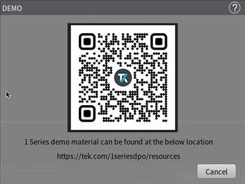
The 1 Series DPO Demo screen has a unique QR code that opens the 1 Series DPO Resource webpage. This contains multiple demo videos and information to get you started with your oscilloscope.
Feature control
The 1 Series DPO offers new ways to enable educators to devote more time to teaching circuit concepts instead of lab setup and management.
Educators can disable autoset, cursors, and automated measurements on the instruments. This allows students to focus on the basic concepts and helps them understand how to use the horizontal and vertical controls to get the waveform display, use the graticule to measure time and voltage, and manually plot/calculate the signal characteristics.
Other products to complete your bench
|
|
|
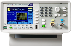
AFG1022 (25 MHz) AFG1062 (60 MHz)
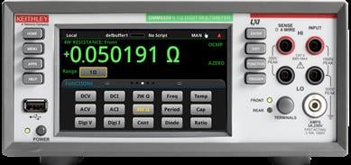
| DMM6500
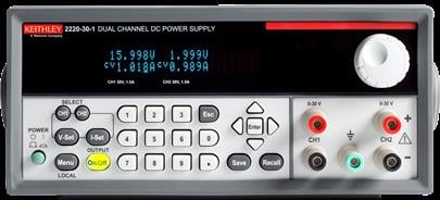
| 2231A-30-3 (3 outputs, 3 A maximum)
|
Specifications
All specifications are typical unless noted otherwise. Specifications that are marked with the ✔ symbol are guaranteed and can be checked using the procedures in the
Model overview
Model | ||||||||
|---|---|---|---|---|---|---|---|---|
No AFG | DPO1052 DPO1052S | DPO1072 DPO1072S | DPO1102 DPO1102S | DPO1202 DPO1202S | DPO1054 DPO1054S | DPO1074 DPO1074S | DPO1104 DPO1104S | DPO1204 DPO1204S |
Analog channels | 2 | 4 | ||||||
Analog channel bandwidth ✔ | 50 MHz | 70 MHz | 100 MHz | 200 MHz | 50 MHz | 70 MHz | 100 MHz | 200 MHz |
Sample rate | 1.25 GS/s half channels 625 MS/s all channels | |||||||
Record length | 10 Mpoints per channel | |||||||
Waveform capture rate | More than 125,000 waveforms per second | |||||||
Vertical resolution | 12 bits | |||||||
AFG output (S models only) | 1 | |||||||
Processor system
Operating system | Closed Linux |
|---|
Vertical system analog channels
Bandwidth selection | 20 MHz and full instrument bandwidth based on model (50 MHz, 70 MHz, 100 MHz, 200 MHz) (limited by instrument bandwidth) |
Input coupling | AC, DC |
Input impedance | 1 MΩ ± 0.02 MΩ |
Input capacitance | 1 MΩ DC coupled, typical, 17 pF (+1 pF / −2 pF) |
Input sensitivity range | 1 mV/div to 10 V/div |
Vertical resolution | 12 bit |
Maximum input voltage | 135 V |
DC gain accuracy ✔ | |
Offset range |
Horizontal system analog channels
Timebase range | 2 ns/div to 1 ks/div (70 MHz, 100 MHz, and 200 MHz bandwidth models) 4 ns/div to 1 ks/div (50 MHz bandwidth model) |
Timebase delay range | −8 divisions to 4000 s |
Timebase accuracy ✔ | ±25 ppm over any ≥1 ms interval (guaranteed for 10 years after factory calibration) |
Trigger system
Trigger modes | Auto, normal, and single |
Trigger coupling | |
Trigger holdoff range | 0 s to 10 s |
Trigger sensitivity | Edge type, DC coupled, any analog input channel:
|
Trigger types |
|
Acquisition system modes
Sample | Acquire sample values |
High Res | Apply a unique bandwidth filter for each sample rate that maintains the maximum bandwidth possible for that sample rate while preventing aliasing and removing noise from the oscilloscope amplifiers and ADC above the usable bandwidth |
Average | Average of a series of acquired waveforms up to 8192 acquisitions |
Waveform measurements
Cursors | Waveform, V bars, H bars, and V&H bars |
Automatic measurements | 23, with up to 21 that can be displayed as either individual measurement badges or collectively in a measurement results table |
Amplitude measurements | Amplitude, maximum, minimum, peak-to-peak, positive overshoot, negative overshoot, mean, RMS, AC RMS, top, base, and area |
Time measurements | Period, frequency, rise time, fall time, +width, -width, +duty, -duty, burst width, setup time, hold time |
Bode plot (FRA) (S model only) |
|
| |
Measurement statistics | Mean, standard deviation, maximum, minimum, and population |
Reference levels | User-definable reference levels for automatic measurements can be specified in either percent or units. Reference levels can be set to global for all measurements or per source channel |
Gating | None, screen, or cursors specify the region of acquisition in which to take measurements |
Waveform math
Number of math waveforms | Up to 4 |
Arithmetic | Add, subtract, multiply, and divide |
Math functions | Integrate, differentiate, log 10, log e, square root, exponential, absolute value, FFT magnitude |
Relational | Boolean result of comparison >, <, ≥, ≤, =, and ≠ |
Logic | AND, OR, NAND, NOR, XOR, and EQV |
FFT | Spectral magnitude |
FFT units | |
FFT window functions | Kaiser-Bessel, Gaussian, Rectangular, Hamming, Hanning, Blackman-Harris, Flattop2, TekExp |
Arbitrary function generator
Number of channels | 1 |
Operating modes | Continuous |
Waveforms | Sine, square, pulse, ramp, arbitrary, dc, and noise |
Signal type | Amplitude range 50 Ω | Amplitude range 1 MΩ | Frequency range |
|---|---|---|---|
Sine | 10 mV to 2.5 V | 20 mV to 5 V | 1 µHz to 25 MHz |
Square | 10 mV to 2.5 V | 20 mV to 5 V | 1 µHz to 10 MHz |
Pulse | 10 mV to 2.5 V | 20 mV to 5 V | 1 µHz to 10 MHz |
Ramp | 10 mV to 2.5 V | 20 mV to 5 V | 1 µHz to 400 kHz |
DC level (offset) | −1.25 V to 1.25 V | −2.5 V to 2.5 V | — |
Random noise | 10 mV to 2.5 V | 20 mV to 5 V | — |
Arbitrary | 10 mV to 2.5 V | 20 mV to 5 V | 1 µHz to 5 MHz |
AM / FM modulation characteristics | |
ASK modulation characteristics | |
FSK modulation characteristics | |
Sweep | |
DC offset |
Additional features
Digital voltmeter | DC, AC+DC RMS, AC RMS; 5-digit resolution |
Frequency counter | Frequency, maximum 6 |
Display
Display type | 7-inch multi-touch capacitive display |
Display resolution | WSVGA 1024 × 600 |
Display mode | Overlay |
Zoom | Horizontal and vertical zooming is supported in all waveform views |
Interpolation | Sin(x)/x and linear |
Waveform styles | Vectors, dots, variable persistence, and infinite persistence |
Graticules | Moveable and fixed graticules, selectable between grid, full, and none |
Format | YT, XY |
Language support | English, Japanese, Simplified Chinese, Traditional Chinese, French, German, Italian, Spanish, Portuguese, Korean |
Input/output ports
USB interface | One USB 2.0 host port (front) One USB 2.0 device port (back) |
Ethernet interface | One ethernet port, 10/100 Mb/s, LAN (VXI11) |
Probe compensation signal, typical | |
Aux out |
Security
Security slot | Rear-panel security slot connects to standard Kensington-style lock |
Mounting
VESA mount | 100 mm × 100 mm VESA interface |
Software
Programming examples | Programming with the 1 Series platform has never been easier. With a programmer manual and the Tektronix GitHub repository, you have many commands and examples to help you get started remotely automating your instrument. See |
Power
Line power | (100 V to 240 V) ± 10% at 50 Hz to 60 Hz |
Power consumption | 45 W (maximum) |
Physical characteristics
Dimensions – instrument only | |
Weight – instrument only | 2.16 kg (4.8 lb) |
Rackmount configuration | 4U |
EMC, environment, and safety
Temperature – operating | |
Temperature – non-operating | −20 °C to 70 °C |
Humidity – operating | 5% to 90% relative humidity at temperatures up to 35 °C 5% to 60% relative humidity at temperatures greater than 35 °C and up to 50 °C |
Humidity – non-operating | 5% to 90% relative humidity at temperatures up to 35 °C 5% to 60% relative humidity at temperatures greater than 35 °C and up to 70 °C |
Altitude - operating | Up to 3,000 meters (9,842 feet) |
Altitude - non-operating | Up to 15,000 meters (48,212 feet) |
Regulatory compliance | For indoor, non-residential use only |
EMC | Conforms to European Union EMC Directive (CE-marked) UK EMC Equivalent: Electromagnetic Compatibility Regulations (UKCA-marked) Ukraine EMC Equivalent: Technical Regulations on Electromagnetic Equipment Compatibility (Ukraine-marked) AUS EMC Equivalent: Australia Radiocommunications Act 1992 (RCM-marked) Korea EMC Equivalent: Registration of Broadcasting and Communications Equipment (KCC-marked) |
Safety | Conforms to European Union Low Voltage Directive (CE-marked) UK LVD Equivalent: Safety Regulations 2016 (S.I. 2016/1101) amended by SI 2019 No. 696 (UKCA-marked) Ukraine LVD Equivalent: Technical Regulation of Low Voltage Electrical Equipment TR 1067 (Ukraine-marked) |
RoHS | Conforms to European Union Restrictions on Hazardous Substances (CE-marked) Conforms to UK RoHS equivalent (UKCA-marked) Conforms to Ukraine RoHS equivalent: (Ukraine-marked) Conforms to China RoHS (China RoHS EFUP marked) |
Ordering information
Use the following steps to select the appropriate instrument and options for your measurement needs.
Step 1 – Select instrument model
Select the 1 Series DPO instrument model.
Model | Description |
|---|---|
DPO1052 | Digital Oscilloscope: 12-bit 50 MHz, 2 analog ch, 1.25 GS/s, 10 M samples/ch, protocol decode I |
DPO1072 | Digital Oscilloscope: 12-bit 70 MHz, 2 analog ch, 1.25 GS/s, 10 M samples/ch, protocol decode I |
DPO1102 | Digital Oscilloscope: 12-bit 100 MHz, 2 analog ch, 1.25 GS/s, 10 M samples/ch, protocol decode I |
DPO1202 | Digital Oscilloscope: 12-bit 200 MHz, 2 analog ch, 1.25 GS/s, 10 M samples/ch, protocol decode I |
DPO1054 | Digital Oscilloscope: 12-bit 50 MHz, 4 analog ch, 1.25 GS/s, 10 M samples/ch, protocol decode I |
DPO1074 | Digital Oscilloscope: 12-bit 70 MHz, 4 analog ch, 1.25 GS/s, 10 M samples/ch, protocol decode I2C, SPI, UART; 1 |
DPO1104 | Digital Oscilloscope: 12-bit 100 MHz, 4 analog ch, 1.25 GS/s, 10 M samples/ch, protocol decode I |
DPO1204 | Digital Oscilloscope: 12-bit 200 MHz, 4 analog ch, 1.25 GS/s, 10 M samples/ch, protocol decode I |
DPO1052S | Digital Oscilloscope: 12-bit 50 MHz, 2 analog ch, 1.25 GS/s, 10 M samples/ch, 25 MHz AFG, protocol decode I |
DPO1072S | Digital Oscilloscope: 12-bit 70 MHz, 2 analog ch, 1.25 GS/s, 10 M samples/ch, 25 MHz AFG, protocol decode I |
DPO1102S | Digital Oscilloscope: 12-bit 100 MHz, 2 analog ch, 1.25 GS/s, 10 M samples/ch, 25 MHz AFG, protocol decode I |
DPO1202S | Digital Oscilloscope: 12-bit 200 MHz, 2 analog ch, 1.25 GS/s, 10 M samples/ch, 25 MHz AFG, protocol decode I |
DPO1054S | Digital Oscilloscope: 12-bit 50 MHz, 4 analog ch, 1.25 GS/s, 10 M samples/ch, 25 MHz AFG, protocol decode I |
DPO1074S | Digital Oscilloscope: 12-bit 70 MHz, 4 analog ch, 1.25 GS/s, 10 M samples/ch, 25 MHz AFG, protocol decode I |
DPO1104S | Digital Oscilloscope: 12-bit 100 MHz, 4 analog ch, 1.25 GS/s, 10 M samples/ch, 25 MHz AFG, protocol decode I |
DPO1204S | Digital Oscilloscope: 12-bit 200 MHz, 4 analog ch, 1.25 GS/s, 10 M samples/ch, 25 MHz AFG, protocol decode I |
Each model includes:
Probes (one per channel):
P2101 100 MHz 1x/10x probe for the 50 MHz, 70 MHz, and 100 MHz models
P2201 200 MHz 1x/10x probe for the 200 MHz model
Installation and safety manual (translated in English, Japanese, and Simplified Chinese)
Embedded help
Power cord
Calibration certificate documenting traceability to National Metrology Institutes and ISO9001 (compliant) quality system registration
Step 2 – Add additional probes and adapters
Add additional recommended probes and adapters.
Passive voltage probes | Description |
|---|---|
TPP0100 | 100 MHz bandwidth, 10X attenuation, BNC interface |
TPP0200 | 200 MHz bandwidth, 10X attenuation, BNC interface |
P2221 | 6 MHz to 200 MHz bandwidth, 1X / 10X attenuation, BNC interface |
P6139B | 500 MHz bandwidth, 10X attenuation, BNC interface |
P6101B | 15 MHz bandwidth, 1X attenuation, BNC interface |
P3010 | 100 MHz bandwidth, 10X attenuation, BNC interface |
Current probes | Description |
|---|---|
TCPA300 | Current probe amplifier; 50 Ω feed-through termination (011-0049-XX) is required |
With TCP312A | DC to 100 MHz, 1 mA |
With TCP305A | DC to 50 MHz, 5 mA |
With TCP303 | DC to 15 MHz, 5 mA |
TCPA400 | Current probe amplifier; 50 Ω feed-through termination (011-0049-XX) is required |
With TCP404XL | DC to 2 MHz, 1 A |
TCP2020 | DC to 50 MHz, 10 mA |
A621 | 5 Hz to 50 kHz, 10 mA to 2000 A |
A622 | DC to 100 kHz |
P6021A | 120 Hz to 60 MHz, 2 mA/mV, 10 mA/mV |
P6022 | 935 Hz to 120 MHz, 1 mA/mV, 10 mA/mV |
TRCP3000 | 1 Hz to 16 MHz, 2 mV/A |
TRCP0600 | 12 Hz to 30 MHz, 10 mV/A |
TRCP0300 | 9 Hz to 30 MHz, 20 mV/A |
CT1 | 25 kHz to 1 GHz, 5 mV/mA |
CT2 | 1.2 kHz to 200 MHz, 5 mV/mA |
CT6 | 250 kHz to 2 GHz, 5 mV/mA |
High voltage single | Description |
|---|---|
P5100A | 500 MHz bandwidth, 100X attenuation |
P6015A | 75 MHz bandwidth, 1000X attenuation |
P5122 | 200 MHz bandwidth, 100X attenuation |
High voltage differential probe | Description |
|---|---|
P5200A | 50 MHz bandwidth, 50:1/500:1 attenuation |
Step 3 – Select accessories
Add additional recommended accessories.
Optional accessories | Description |
|---|---|
1-RK | Rackmount kit |
1-SC | Carrying bag |
1-HC | Hard carrying case |
Step 4 – Select power cord option
Optional accessories | Description |
A0 | North America power plug (115 V, 60 Hz) |
A1 | Universal Euro power plug (220 V, 50 Hz) |
A2 | United Kingdom power plug (240 V, 50 Hz) |
A3 | Australia power plug (240 V, 50 Hz) |
A5 | Switzerland power plug (220 V, 50 Hz) |
A6 | Japan power plug (100 V, 50/60 Hz) |
A10 | China power plug (50 Hz) |
A11 | India power plug (50 Hz) |
A12 | Brazil (60 Hz) |
A99 | No power cord |
E1 | Universal euro bundle |
Step 5 – Select service options
Protect your investment and your uptime with a service package for your 1 Series DPO.
Optimize the lifetime value of your purchase and lower your total cost of ownership with a calibration and extended warranty plan for your 1 Series DPO. Plans range from standard warranty extensions covering parts, labor, and 2-day shipping to Total Product Protection with repair or replacement coverage from wear and tear, accidental damage, ESD or EOS. See the table below for specific service options available on the 1 Series DPO family of products. Compare factory service plans
Additionally, Tektronix is a leading accredited calibration services provider for all brands of electronic test and measurement equipment, servicing more than 140,000 models from 9,000 manufacturers. With 100+ labs worldwide, Tektronix serves as a global partner, delivering tailored whole-site calibration programs with OEM quality at a market price. View whole site calibration service capabilities at
Service options | Description |
|---|---|
R3 | Three-year total protection plan includes repair or replacement coverage from wear and tear, accidental damage, ESD or EOS plus preventative maintenance. Including a 5 |
R5 | Five-year total protection plan includes repair or replacement coverage from wear and tear, accidental damage, ESD or EOS plus preventative maintenance. Including a 5 |
T3 | Three |
T5 | Five-year total product protection plan includes all features of extended warranty plan plus complete coverage against accidental damage, user |
CD1 | Calibration with full data report service. Includes traceable calibration with full data report, or functional verification where applicable. Coverage includes 1 calibration event over 3 years. |
CD3 | Calibration with full data report service for 3 years. Includes traceable calibration with full data report, or functional verification where applicable. Coverage includes 3 calibration events over 3 years. |
CD5 | Calibration with full data report service for 5 years. Includes traceable calibration with full data report, or functional verification where applicable. Coverage includes 5 calibration events over 5 years. |
Additional software for extended functionality
Purchase additional software with flexible licensing to extend the capabilities of your instrument for collaboration and offline analysis. Option bundles with different levels of functionality are being offered to suit different application needs. Each of these bundles can be purchased as a 1-year subscription or as a perpetual license.
Software option | Description |
|---|---|
TEKSCOPE-STARTER | TekScope PC software bundles for various applications |
TEKSCOPE-ULTIMATE |