お問い合わせ
ダウンロード
マニュアル、データシート、ソフトウェアなどのダウンロード:
フィードバック
TekExpress LVDS Txテストソフトウェア 5/6シリーズMSO & MSO/DPO70000Cシリーズ
Option 5/6-DBLVDS & LVDSTXデータ・シ-ト
詳細情報
オンラインで読む:


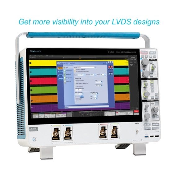
The Tektronix TekExpress® LVDS (Low Voltage Differential Signaling) solution (Option 5/6-DBLVDS or LVDSTX) offers a complete physical layer measurement and debug solution for transmitter conformance and characterization of various variants of LVDS. The automated solution works with Tektronix 5/6 Series MSO and MSO/DPO70000C oscilloscopes and provides an easy way to characterize the electrical and timing measurements of LVDS signals.
The application is used to test LVDS data ranging from 100 Mbps to 6 Gbps, based on the standard under test.
Key features
- Fully automated Tx solutions: Complete automation of 30+ tests on multiple LVDS variants.
- Multiple LVDS standards: Measurements with debug capability on multiple LVDS variants supported.
- Configurable test, test settings, and test limits: Select a set of tests relevant to a given specification, use the settings for accurate results, and measure them against the configured limits value.
- Automatic mask: Automatic mask generation for a given data rate, signal levels, and mask shape.
- Generic clock recovery configuration: Fully configurable clock recovery options for all embedded clock LVDS standards.
- Reference level and filter file selection: Configurable reference level and filter settings for video standards.
- Multi-run support: The application supports multiple runs of tests to characterize the Device Under Test.
- TekExpress remote API - SCPI: The application can be remotely controlled by scripts using SCPI commands.
- Multiple report formats: Reports can be generated in CSV, MHT, and PDF format.
- Works on MSO/DPO70000C Series and 5/6 Series MSO: Supports 5/6 Series and MSO/DPO70000C oscilloscopes over all bandwidths.
Applications
- Display controllers
- Video applications
- IOT Sensors
- Data convertors
- Cameras/industrial cameras
- Machine vision/robotics
- Serializer/deserializer
Automated LVDS measurements
The Tektronix TekExpress LVDS automated test solution runs on the 5/6 Series MSO and MSO/DPO70000C oscilloscopes with the Windows 10 operating system. The close integration of the oscilloscope and test solution provides a simple, automated, and efficient way to measure the parameters of LVDS transmitter interfaces and devices.
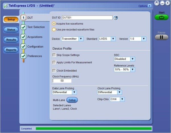
A well-designed workflow-based user interface steps you through test setup and execution
Measurement setup and test execution is simple with the LVDS application. The Graphical User Interface (GUI) is laid out to represent the workflow from setup through testing.
The workflow consists of choosing tests associated with qualifying a DUT, setting the parameters for clock recovery and mask settings in the configuration tab, and giving preferences for reporting.
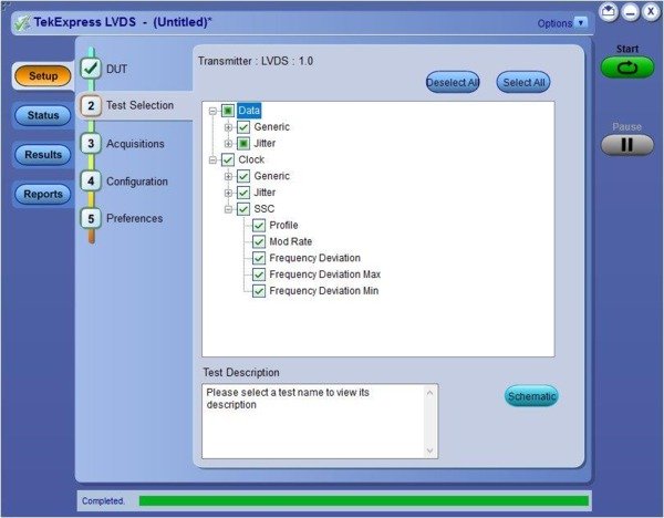
Select test groups or individual tests from the Test Selection menu
Clock recovery
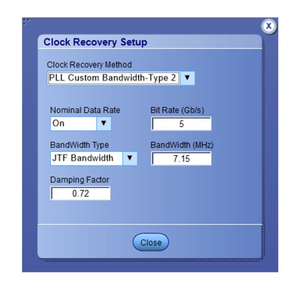
A recovered clock is used to perform data analysis on the video standards. The LVDS application has a built-in generic clock recovery feature. The clock recovery parameters are set based on the requirements of the standard under test. You can configure the clock recovery method, nominal data rate, JTF bandwidth, and damping factor.
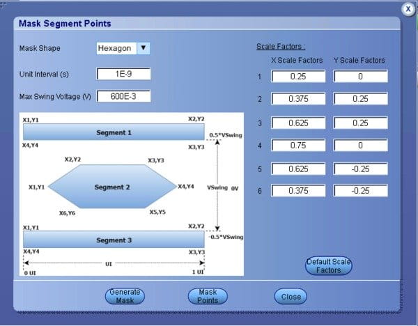
Auto mask generation
Mask testing is an important requirement for testing to video specifications. The application can generate the relevant mask based on the data rate (UI), voltage levels, and mask shape. The availability of a mask test gives first-hand information on the quality of the signal.
Pass/Fail report
The test report tab provides a view of the complete test results, pass or fail status along with min/max permissible values, and margin available for each of the tests. Images supporting the test results for each lane of the DUT are also displayed in the report. The reports are generated in PDF, .MHT, and CSV formats.
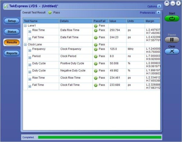
A detailed report provides a record of test results
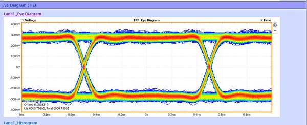
TIE Eye diagram
Test setup and probing
The test setup consists of DUTs with +ve and -ve outputs connected to the oscilloscope through cables or differential probes. In the case of a differential probe, the maximum number of lanes supported are same as the maximum number of channels available on the oscilloscope. The MSO58 can support up to eight tightly aligned lanes with differential probes. For each lane, a pair of phase-matched cables can also be used to connect to the oscilloscope.
Oscilloscope: An ideal option would be to choose an oscilloscope which meets the bandwidth requirements of the signal. The oscilloscope is expected to give a true representation of the signal with minimal addition of artifacts from its own hardware. One key advantage in LVDS is that the differential pair of traces cancels out any external influence on the signal as it affects both traces equally.
The 5/6 series oscilloscopes come with 12-bit ADCs and matching low noise front end amplifier. This gives an advantage of 16 times higher resolution. The high resolution and low noise performance of the oscilloscope gives very accurate representation of the signal. For example, when the vertical offset setting is configured as 1 mV/div, 1 GHz oscilloscope has a noise of 54.8 μV and 8 GHz oscilloscope has a noise of 158 μV. Implying, the signal reproduced has very little additive noise from oscilloscope hardware. The 5 Series MSO can support signals with bandwidth up to 2 GHz and the 6 Series MSO supports signals with bandwidth up to 8 GHz. Signals with bandwidth beyond 8GHz can be tested on 70000C oscilloscopes.
Probes: 5/6 series mixed signal oscilloscopes support TDP7700 Series TriMode™ Probes. DPO/MSO70000C Oscilloscope support P7700 Series TriMode Probes. Both probe series offer high bandwidth, low loading, and flexible connections, and can make single-ended, differential, and common mode measurements without reconnecting.
Tests supported
Test on Data Lanes
- Generic test
- Unit Interval
- Rise Time
- Fall Time
- Data Width
- Data Intra Skew (PN)
- Data Inter Skew
- Data Peak-To-Peak (Lane-To-Lane)
- Jitter test
- AC Timing
- Clock Data Setup Time
- Clock Data Hold Time
- Eye Diagram (TIE)
- TJ@BER
- DJ Delta
- RJ Delta
- DDJ
- TnT
Test on Clock Lanes
- Generic test
- Frequency
- Period
- Duty Cycle
- Rise Time
- Fall Time
- Clock Intra Skew (PN)
- Data Peak-To-Peak
- Jitter test
- TIE
- TJ
- DJ
- RJ
- SSC On
- Profile
- Mod Rate
- Frequency Deviation Mean
- Frequency Deviation Min
- Frequency Deviation Max
Specifications
All specifications are guaranteed unless noted otherwise.
- Probing configuration
- Phase-matched SMA / Differential Probes
- Triggering
- All the tests work on edge trigger. The application oscilloscope settings can be overridden by enabling "Skip Scope Setting" checkbox in the DUT panel
- Report output formats
- CSV, PDF, and MHT formats with images of all acquired waveforms
Ordering information
Hardware requirements
| Model | Description |
|---|---|
| Oscilloscope | 5/6 Series MSO or MSO/DPO70000C oscilloscope. Select the Bandwidth of the oscilloscope based on the standard under test. |
| Required option |
|
Software requirements
| Application | 5 Series MSO | 6 Series MSO | MSO/DPO70000C | License type |
|---|---|---|---|---|
| TekExpress LVDS Tx Test Automation Software | 5-DBLVDS | 6-DBLVDS | LVDSTX | New instrument license |
| SUP5-DBLVDS | SUP6-DBLVDS | DPO-UP LVDSTX | Upgrade license | |
| SUP5- DBLVDS-FL | SUP6- DBLVDS-FL | DPOFL-LVDSTX | Floating license |
Recommended probes
| Probes | Quantity |
|---|---|
| For 5/6 Series MSO: TDP7700 Series TriMode (TM) Probes | One each (Embedded Clock), minimum |
| For MSO/DPO70000C Series: P7700 Series TriMode Probes | One each (Embedded Clock), minimum |
| Phase Matched Cables | One pair, minimum |
| Bandwidth of probes is based on the standard under test | |


