Contact us
Live Chat with Tek representatives. Available 6:00 AM - 4:30 PM
Call us at
Available 6:00 AM – 5:00 PM (PST) Business Days
Download
Download Manuals, Datasheets, Software and more:
Feedback
Ethernet (2.5G, 5G, and 10G) Electrical Testing Software for 6 Series and 6 Series B MSO
Option 6-CMNBASET and 6-CMXGBT Application Datasheet
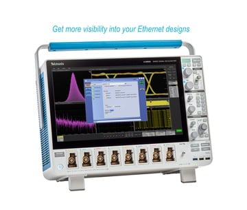
The Ethernet Transmitter Test application automates 10GBASE-T, NBASE-T (2.5GBASE-T and 5GBASE-T), and IEEE802.3bz (2.5G/5G) physical medium attachment (PMA) physical-layer (PHY) electrical testing to provide a fast and accurate way of testing your ethernet designs.
Based on the TekExpress test automation framework, the Ethernet Transmitter Test application performs all PMA electrical measurements as specified by the IEEE802.3an standard, the IEEE802.3bz standard, and the NBASE-T specification. This allows you to quickly and efficiently test ethernet devices running at 2.5G, 5G, and 10G data rates.
To accurately make these measurements, you need the Tektronix TF-XGBT test fixture. The TF-XGBT test fixture allows you to easily access the device under test (DUT) using either differential probes or matched SMA cables.
Key features
Comprehensive automated solution for 2.5GBASE-T, 5GBASE-T and 10GBASE-T PHY testing
Highly optimized and user friendly interface flow that sets up the test configuration for quick validation of electrical signals.
Compliance and margin testing for accurate analysis and improved interoperability.
Time-domain and frequency-domain measurements made with single analysis instrument.
Test execution on an oscilloscope with remote control using programmatic interface from an external PC.
Single instrument analysis of time and frequency domain measurements.
Signal acquisition and analysis support for differential probes or direct SMA cabling.
Test selection and instrument setup
Test selection is easy and straight forward through the intuitive TekExpress workflow. Select the measurements to execute and click on Start button.
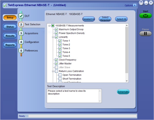
For each measurement selected, the Ethernet Transmitter application automatically configures the oscilloscope, saving setup time and ensuring repeatable, reliable results.
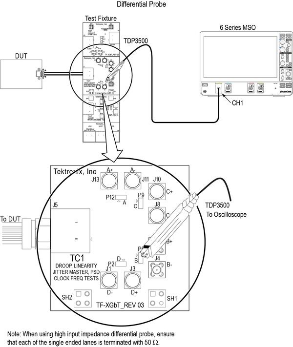
As each test is performed, the application guides you through the connection diagrams.
Reports
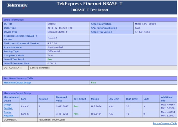
A summary report with Pass/Fail status for each test is created after the test execution is complete. This report includes test configuration details, waveform plots, and margin analysis to provide more insight into your design.
Margin testing
You can make changes to test specific parameters like test limits and other parameters to perform detailed margin analysis to validate your device performance.
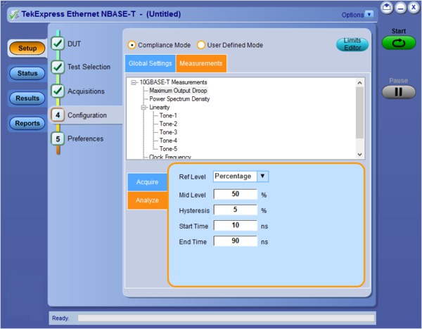
Probe support for signal acquisition
The application allows signal acquisition and analysis with either matched pair SMA cables or differential probes.
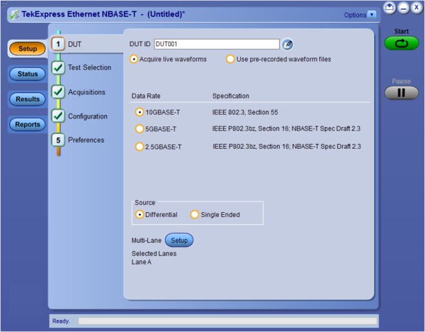
Return loss
The automated test application simplifies Return Loss testing and eliminates the need for a Vector Network Analyzer by using a patented oscilloscope-based measurement along with a Tektronix AWG. Calibration data for Open, Load, and Short can be stored in a file and recalled in the test application.
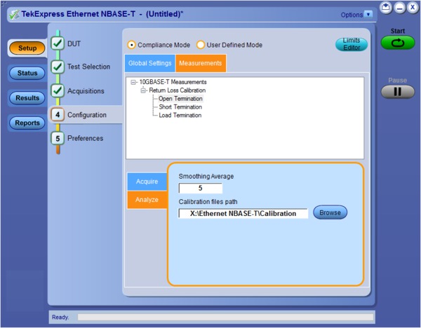
Complete programming interface
The TekExpress application provides a programmatic interface with support for a high-level automation layer such as Visual Basic, Microsoft.Net, C#, C++, Python, or any other web application. This lets you control the execution of the TekExpress Ethernet application running on an oscilloscope from a local machine or using a remote computer.
Programming examples are found in the application examples folder.
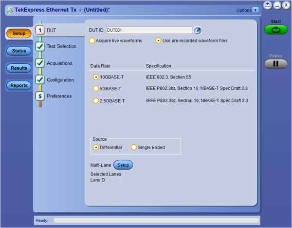
Pre-recorded waveform analysis
Offline analysis feature of the TekExpress Ethernet application allows the user to analyze the already acquired waveforms. Select Use pre-recorded waveform files in the application DUT panel to acquire the waveforms and save it as a waveform files.
This allows the waveforms to be captured from an oscilloscope and shared across multiple users, sites to perform analysis using other oscilloscopes.
Specifications
- 10GBASE-T measurements
The following tests are performed as per the IEEE802.3-2012 standard. The device under test (DUT) must be able to provide the test mode signals as indicated in IEEE802.3-2012 Subclause 55.5.2.
Measurement Standard reference and Test mode Maximum Output Droop
IEEE802.3-2012 Subclause 55.5.3.1 Transmitter Timing Jitter - Master
IEEE802.3-2012 Subclause 55.5.3.3 Transmit Clock Frequency
IEEE802.3-2012 Subclause 55.5.3.5 Transmitter Timing Jitter - Slave
IEEE802.3-2012 Subclause 55.5.3.3 Transmitter Linearity
IEEE802.3-2012 Subclause 55.5.3.2 Transmitter Power Spectral Density (PSD) and Power
IEEE802.3-2012 Subclause 55.5.3.4 Return Loss
IEEE802.3-2012 Subclause 55.8.2.1
- 2.5GBASE-T and 5GBASE-T measurements
The following tests are performed as per the IEEE802.3bz/D3.3 draft standard. The device under test (DUT) must be able to provide the test mode signals as indicated in IEEE802.3bz/D3.3 Subclause 126.5.2.
Measurement Test mode Maximum Output Droop
IEEE80.bz/D3.3 Subclause 126.5.3.1 Transmitter Timing Jitter - Master
IEEE80.bz/D3.3 Subclause 126.5.3.3 Transmit Clock Frequency
IEEE80.bz/D3.3 Subclause 126.5.3.5 Transmitter Timing Jitter - Slave
IEEE80.bz/D3.3 Subclause 126.5.3.3 Transmitter Nonlinear Distortion
IEEE80.bz/D3.3 Subclause 126.5.3.2 Transmitter Power Spectral Density (PSD) and Power
IEEE80.bz/D3.3 Subclause 126.5.3.4 Return Loss
IEEE80.bz/D3.3 Subclause 126.8.2.1
- NBASE-T measurements
The following tests are performed as per the NBASE-T Physical Layer Specification. The device under test (DUT) must be able to provide the test mode signals as indicated in NBASE-T Physical Layer Specification version 1.1 Subclause 2.9.
Measurement Test mode Maximum Output Droop
Subclause 55.5.3.1, Test Mode 6 Transmitter Timing Jitter - Master
Subclause 55.5.3.3, Test Mode 2 Transmit Clock Frequency
Subclause 55.5.3.5, Test Mode 2 Transmitter Timing Jitter - Slave
Subclause 55.5.3.3, Test Mode 1 and Mode 3 Transmitter Nonlinear Distortion
Subclause 55.5.3.2, Test Mode 4, Tones 1-5 Transmitter Power Spectral Density (PSD) and Power
Subclause 55.5.3.4, Test Mode 5 Return Loss
Subclause 55.8.2.1, Test Mode 5
Ordering information
Required hardware
| Oscilloscope | 6 Series / 6 Series B MSO oscilloscope with minimum bandwidth of 4 GHz (option 6-BW-4000) |
| Supported instruments | MSO64 |
| Required option | 6-WIN (Removable SSD with Microsoft Windows 10 operating system) |
Software models
| Application | Option | License type |
|---|---|---|
Ethernet (2.5G and 5G BASE-T) Automated Compliance Solution | 6-CMNBASET | New instrument license |
SUP6-CMNBASET | Upgrade license | |
SUP6-CMNBASET-FL | Floating license | |
Ethernet (10G BASE-T) Automated Compliance Solution | 6-CMXGBT | New instrument license |
SUP6-CMXGBT | Upgrade license | |
SUP6-CMXGBT-FL | Floating license |
Recommended probes
| Probes | Quantity |
|---|---|
| TDP3500 | 1 (minimum) 1 |
Recommended accessories
| Accessories | Quantity |
|---|---|
| Power Splitter - PSPL5331 | 2 |
| SMA to BNC adopter PN: 015057200 | 4 |
AWG compatibility (For Return Loss Measurements)
AWG5202 with option 250,2HV and 2DC (recommended), AWG7122C
IEEE 2.5GBASE-T Transmitter Non-linear Distortion Test (Section 126.5.3.2)
This test requires a 45 MHz sine wave to be injected, as per the specification. This is only required for 2.5GBASE-T. The supported signal sources are:
- AWG5202 with option 250, 2HV and 2DC is recommended for NBaseT (2.5G/5G/10G) compliance testing.
TF-XGBT 10GBASE-T, NBASE-T, and IEEE802.3bz
The TF-XGBT test fixture is required to perform all measurements and is designed to meet the test fixture requirements in each of the applicable specifications/standards.
| TF-XGBT contains | Quantity | Description |
|---|---|---|
| Test fixture main board | 1 | Main test fixture consist of 3 sections:
|
| Test fixture calibration board | 1 | Required for Return Loss calibration |
| RJ45 patch cord | 2 | 0.08 meter, shielded RJ45 cable to connect the test fixture to the Return Loss calibration board and the device under test |


