
After years of research and design, Silicon Carbide (SiC) and Gallium Nitride (GaN) power devices are becoming more viable. But, these devices, though high performance, come with challenges, including gate drive requirements. SiC requires much higher gate voltage (Vgs) with a negative bias for turn off. GaN, on the other hand, has much lower threshold voltage (Vth), requiring tight gate drive designs. Wide band gap (WBG) devices, by the nature of their physics, also have a higher body diode voltage drop that requires much tighter control of dead-time and turn-on/turn-off transitions.
Accurate electrical source and measure testing is essential for characterizing these high voltage devices so that the right design decisions can be made in a timely fashion. Increasing design margins and overdesigning will only drive costs up and bring performance down. And, typically high voltages greater than 200 V are involved, so safety from harmful voltage is critical.
High Voltage Device Tests
Basic characterization of high voltage semiconductor devices typically involves a study of the breakdown voltage and leakage current. These two parameters help device designers to quickly determine whether the device was correctly manufactured and whether it can be effectively used in the target application.
Breakdown Voltage Measurements
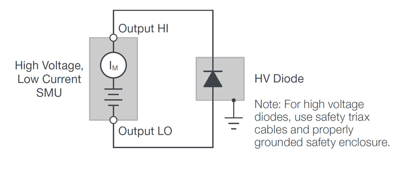
Measuring breakdown voltage is done by applying an increasing reverse voltage to the device until a certain test current is reached that indicates that the device is in breakdown. Figure 1 illustrates a breakdown measurement on a high voltage diode using a source measure unit (SMU) instrument - like Keithley’s 2470 High Voltage SourceMeter® SMU Instrument. Note how the SMU instrument is connected to the diode’s cathode to apply a reverse voltage.

Figure 1. Typical breakdown voltage measurement of a high voltage diode using the 2470 High Voltage SMU Instrument.
In qualifying breakdown voltage, measurements are typically made well beyond the expected rating of the device to ensure that the device is robust and reliable. A SMU instrument such as the 2470 that has 1100 V sourcing capability is typically high enough to test many of today’s SiC and GaN devices as well as future device designs.
Safety Considerations
When testing at high voltage, safety is critical, and precautions must be taken avoid exposure to unsafe voltage:
- Enclose the device under test (DUT) and any exposed connections in a properly grounded fixture such as the fixture shown in Figure 2.
- Ideally, the SMU instrument will feature a safety interlock as shown on the rear panel of the 2470 in Figure 3. The 2470 is fully interlocked so that the high voltage output is turned off if the interlock is not engaged (interlock switch closed.) The interlock circuit of the SMU instrument should be connected to a normally-open switch that closes only when the user access point in the system is closed to ensure that operators cannot meet a high voltage connection to the DUT. For example, opening the lid of the test fixture should open the switch/relay that disengages the interlock of the 2470 SMU.
- Use cables and connectors rated to the maximum voltage in the system. Keithley’s TRX-1100 V high voltage triax cables are designed for the 2470 and meet today’s high voltage safety standards.
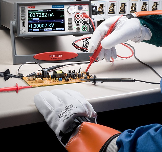
- Always use the proper safety gloves when working with high voltages on energized components as shown in Figure 4.

Figure 2: Properly grounded testing fixture.

Figure 3: Location of safety interlock connection on rear panel of Keithley’s 2470 SMU Instrument.

Figure 4. Use proper safety gloves when working with high voltages on energized components.
Leakage Current Measurements
In a typical power conversion application, the semiconductor device is used as a switch. Leakage current measurements indicate how closely the semiconductor performs to an ideal switch. Also, when measuring the reliability of the device, leakage current measurements are used to indicate device degradation and to make predictions of device lifetime.
Semiconductor researchers are finding materials to make higher quality switches and produce high power devices with very small leakage currents. SMU instruments like the Keithley 2470 offer precision low current measurement capabilities with measurement resolution as low as 10 fA.
To prevent unwanted measurement error when measuring currents less than 1 μA, use triaxial cables and electrostatic shielding. Triaxial cables are essential in part because they permit carrying the guard terminal from the current measurement instrument. Guarding eliminates the effect of system leakage currents by routing them away from the measurement terminal. Use an electrostatic shield to shunt electrostatic charges away from the measurement terminal. An electrostatic shield is a metal enclosure that surrounds the circuit and any exposed connections. The safe test enclosure may serve as an electrostatic shield.
Characterizing a SiC Power Diode with Keithley’s 2470 SMU Instrument and KickStart Software
Coupling a 2470 SMU Instrument with Keithley’s KickStart Software is an accurate, safe and quick way to test breakdown voltage and reverse leakage current on high voltage semiconductor devices. To learn how this combination successfully addresses the inherent challenges, download the application note Breakdown and Leakage Current Measurements on High Voltage Semiconductor Devices Using the
Keithley 2470 SourceMeter® Source Measure Unit (SMU) Instrument and KickStart Software.


