This article is adapted from a presentation at the March 2021 Meeting of the American Physical Society by Brad Odhner, Technical Marketing Manager, Keithley Instruments, Inc., a Tektronix company.
Quantum Basics
To understand how to create an efficient test & measurement topology for quantum research applications, let’s begin with a 10,000-foot overview of some of the basics of quantum computing. The first concept to grasp is the qubit (short for “quantum bit”), the basic unit of quantum information. Essentially, a qubit is the quantum version of the classic binary bit physically realized with a two-state device. In a classical system, a bit would be in one state or the other (either a 0 or a 1). However, quantum mechanics allows the qubit to be in a superposition of both states simultaneously, a property that’s fundamental to quantum mechanics and quantum computing. A qubit can be Up, Down, or Up & Down. So instead of the classic binary 1 and 0 with register of 01 or 10, quantum mechanics allows for a trinary logic system with eight potential outcomes from a single qubit. Just five qubits can produce 32,768 outcomes, as opposed to a standard computer offering just 32 outcomes. This allows solving huge problems instantly simply by running every permutation.
However, multiple types of qubits can be used in quantum computing. Qubits in the semiconductor space are probably the most commonly used. Given some of the technology advancements likely to emerge within the next few years, the semiconductor space also seems to be the fastest emerging, most realizable option for developing a full quantum computer into silicon, at scale, and eventually into a commercially available project. Ion traps is probably the next state of qubit in terms of observability or viability. Ions (charged atomic particles) can be confined and suspended in free space using electromagnetic fields, allowing qubits to be stored in stable electronic states of each ion, and quantum information can be transferred through the collective quantized motion of the ions in a shared trap. However, setting up successful experiments is much more difficult in the trapped ion space than in the semiconductor space because it requires much more equipment, is harder to scale, and poses greater challenges for making observations, and transferring those observations into potentially commercial technologies. Flying qubits are currently out there on the edge of possibility, are rarely used right now, and are hard to research because of the difficulty of observing proper quantum behavior with them.
At Tektronix, we see many similarities across some seemingly disparate categories of research. For example, research always demands the use of calibrated test and measurement equipment, such as signal sources, which are, at their core, an effort to calibrate and transmit what could be a realized state of phenomena. Signal sources can be used to rerun and validate what was observed, either in a natural state or a previously recreated state and duplicate the same scenario with a high degree of integrity, calibration, and precision. After sourcing the necessary signals, the next step is experimentation to verify a hypothesis, followed by analysis of results. Let’s consider an example of an experimental setup for quantum computing research (Figure 1).
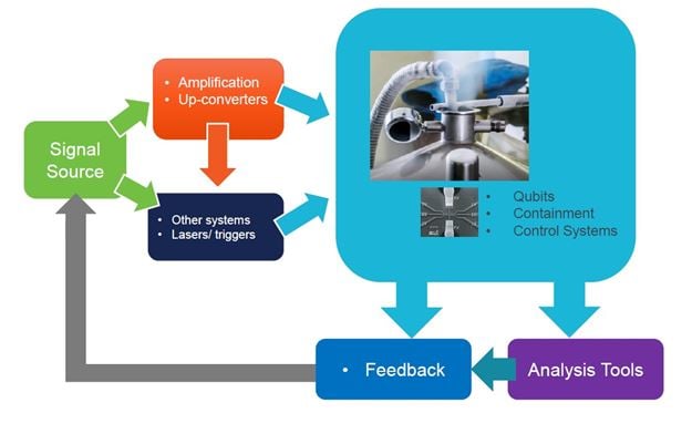
Figure 1. Quantum computing experimental setup.
A containment device, typically a cryogenic chamber, is located at the center of the experimental setup, where qubits can operate. The kinds of small, simple experiments that can be performed have several goals: managing and controlling these qubits to achieve the eight different states mentioned previously; getting multiple qubits working side by side with some element of control within the chamber; and observing and managing that process. From a test and measurement perspective, the signal source is the real heart of the test setup because it provides that baseband generation of signals into the containment system that are enhanced through amplifiers, up-converters, RF conversion, and different trigger types. These components allow modifying the experiments to determine just how much control can be applied and what the control does to manipulate the mechanics and the individual qubits in that controlled system. Figure 2 illustrates the qubit calibration flow, which explains what’s going on in the test setup
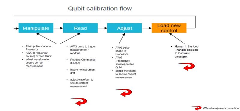
Figure 2. The qubit calibration flow has four main stages: manipulate, read, adjust, and load new content.
The AWG (Arbitrary Waveform Generator) in this calibration flow is a class of widely available signal sources. In the “manipulate” stage, an AWG is used to excite the qubit and move it to a particular state. The AWG can send a pulse shape to the processor in the experimental system and use the waveform to adjust the qubit, secure correct measurements for that processor, and eventually excite that qubit into some state. The manipulate stage also includes measurement self-calibration by using the AWG to observe. In the “read” phase, the AWG pulse can trigger an oscilloscope measurement or a readout into some other measurement system, such as an FPGA-based system. The AWG can also perform the waveform adjustments necessary for a correct measurement. So, in some cases, researchers work with the AWG to correct that waveform by making small adjustments to capture the measurement desired. The waveform being modified is the same file the AWG uses for generation. Researchers can correct waveform files using tools like those in MATLAB® or proprietary tools like Tektronix's SourceXpress® software. In this setup, the oscilloscope is primarily reading the commands, confirming through visualization that those commands are being sent and received by the controller.
The heart of the experimental process takes place in the “adjust” stage. The AWG's pulse shape can be modified to support the processor requirements by modifying the frequency or the up-conversion, or by adjusting the sample rate to determine what's needed to excite a qubit to move it into a different state. Researchers can continue to adjust and correct that waveform and sequencing of all the different waveforms coming out of the AWG. Next, it's time for the researcher to reconduct the experiment. Timing is critical in quantum experiments, so researchers need signal sources that can recompile and resend a waveform fast when modifying feedback loops.
AWGs are far from the only types of signal sources being used in quantum research. Other options include vector signal generators (VSGs), combinations of digital to analog converters (DACs) and field-programmable gate arrays (FPGAs), and microwave generators. Each signal source option has pros and cons attached, but the ability to rely on the output of a signal source is essential to maintaining consistency and confidence in quantum experiments over time. Noise from the signal source can impact the qubit exciter load, as well as any command language being sent within the signal waveform. Digital and analog channel counts are also important because exciting a qubit state requires multiple channels. Often, the need for high channel counts demands the use of stacks of instruments, which can make finding enough physical space to house them all and the development time needed to assemble the system a significant problem. Quantum setups are extremely complex to assemble because each quantum bit or experiment can require multiple, independent (not multiplexed) signals, and each signal may require its own up-conversion, predistortion and conditioning. Masses of cabling are necessary to connect all these pieces. Given the number of components involved when scaling a system across multiple signal source channels, having a common time reference is vital to accurate system synchronization and triggering. Minimal skew that’s adjustable to account for any unavoidable timing delays in the system and the ability to maintain low timing jitter over time are equally crucial.
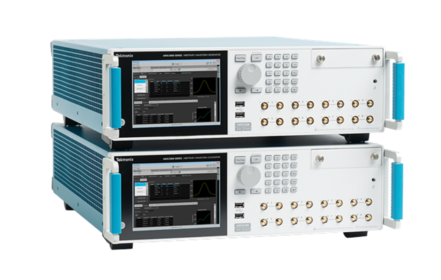
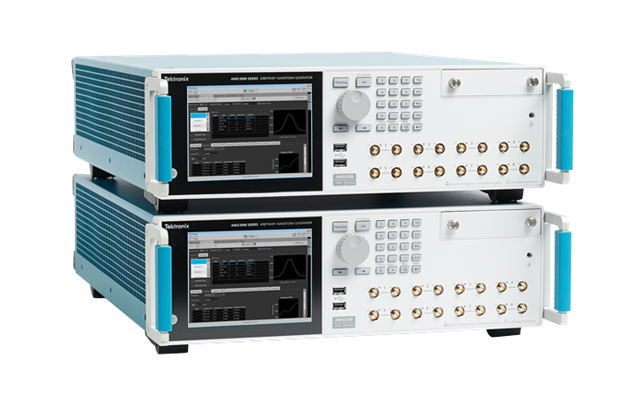
Figure 3. Two AWG-5208 8-channel Arbitrary Waveform Generators can be easily synched to create a 16-channel configuration when scaling up a quantum research setup.
A number of instrument manufacturers are working to simplify this complex system building process by combining multiple signal generation and feedback capabilities into a single box. For example, Tektronix’s AWG5200 Series of Arbitrary Waveform Generators (Figure 3) were designed to provide good baseband generation support with high integrity output for quantum computing experiments. The AWG5200 offers 16-bit DAC resolution, 2GSamples of memory per channel, and sample rates up to 10G samples/second. Direct generation of RF signals, the ability to build setups with pre-calibration and pre-compensation s-parameter software, and low SFDR help ensure signal accuracy. A choice of 2-, 4-, and 8-channel configurations with AC and DC output options and multi-unit synchronization allow for more efficient and cost-effective system scaling. Both MATLAB commands and SourceXpress software are compatible with the AWG5200 for modifying waveforms.
To learn more about the latest quantum computing research solutions, visit http://www.tek.com/.