Radar systems can use continuous wave (CW) signals or, more commonly, low duty-cycle pulsed signals. Although there are several continuous transmission types of radar, primarily Doppler, the great majority of radars are pulsed. The RF pulse characteristics reveal a great deal about a radar's capability. Electronic Warfare (EW) and Electronic lntelligence (ELINT) experts specialize in the study of these pulsed signals. Pulse characteristics provide valuable information about the type of radar producing a signal and what its source might be – sailboat, battleship, passenger plane, bomber, missile, etc.
Choosing Measurement Parameters
There are several parameters that you must set correctly before measurements of radar pulses should be attempted. These affect the processing of pulsed signals and are dependent upon the character of the signal and on the desired interaction of the instrument with the incoming pulses.
Here are five parameters to consider:
- Measurement Filter Type – A crucial parameter when measuring a pulse signal is the measurement filter type and bandwidth. Once the analog signal is digitized (using either a spectrum analyzer or an oscilloscope) further digital processing can reduce and shape the measurement bandwidth. Narrower bandwidth filters will reduce the noise within the measurement and therefore reduce the uncertainty of some measurement parameters. However, this is only useful in cases where the incoming pulse to be measured does not contain spectral components wider than the applied filter (either fast rise/fall edges, or wide frequency/phase modulations). For example, rise time measurement uncertainty is increased with narrow filters due to the high-frequency components in pulse edges. Narrow filters can also introduce distortion like overshoot and ringing.
One filter type that minimizes these induced artifacts is a Gaussian-shaped filter. Compared to a basic band-pass or rectangular filter, a Gaussian filter type introduces very little pulse distortion and should be selected if overshoot or ringing of the pulse must be minimized. Still, if the pulse is wideband enough that the widest Gaussian filter will be too narrow, then it’s better to not use any post-acquisition filtering at all and either limit bandwidth by changing instrument settings or use the maximum available bandwidth.
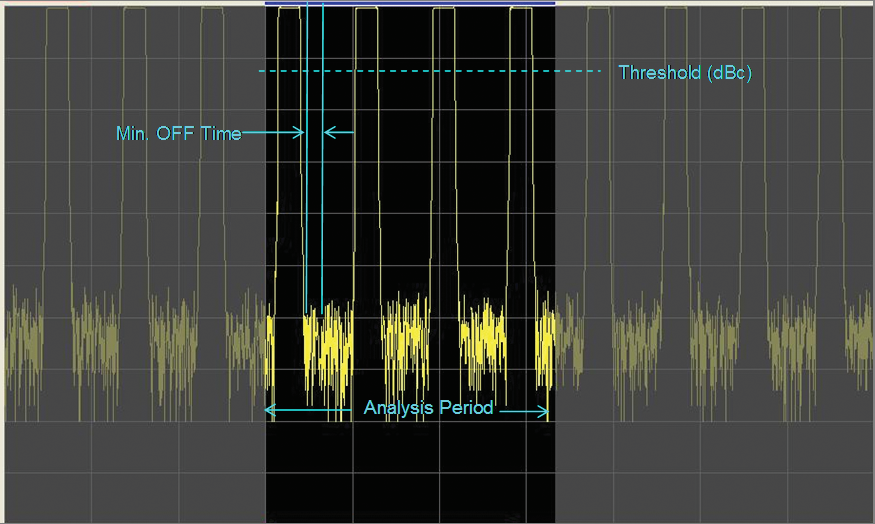
- Pulse Detection Threshold – A typical radar pulse detection algorithm requires a set threshold amplitude. In some cases, there may be variations in the noise floor, and you rarely want to measure on noise. In an off-the-air situation it may be desirable to only measure the highest amplitude pulses from a nearby transmitter. Ideally, you would want to search the acquired record and find the pulse top first, then decide if any pulses exist. You can do that by comparing the supposed pulse top to the surrounding signal and compare to a defined dBc, or decibels below the pulse top (see Figure 1). This method helps prevent measurements from triggering on noise.

Figure 1. Pulse detection threshold is best specified in terms of dB from a carrier level.
- Minimum Off Time – Some pulses may not have flat tops. A pulse may also have intentional amplitude variations across the top including a reduction in amplitude that may cause a pulse detector to incorrectly find two separate pulses. In this case, it can be helpful to specify a minimum off time. This allows for a pulse with an amplitude dip below the threshold, but of a duration shorter than the minimum off time, to be properly detected.
- Number of Pulses to Measure – You need to determine the number of pulses required for detailed statistics on the trends of pulse parameters. When you’re not interested in trends of the measurement over time, you’ll rarely need to measure parameters for every pulse in an acquisition. If the measurement does not need all the available pulses, then entering a smaller, set number to measure on can vastly reduce the time needed to process the data and get results.
- Droop Compensation and Rise/Fall Time – Rise time and fall time measurements have two different definitions. Many measurements use 10% to 90% of full amplitude as the definition of the transition time, but in some cases the definition is 20% to 80%.
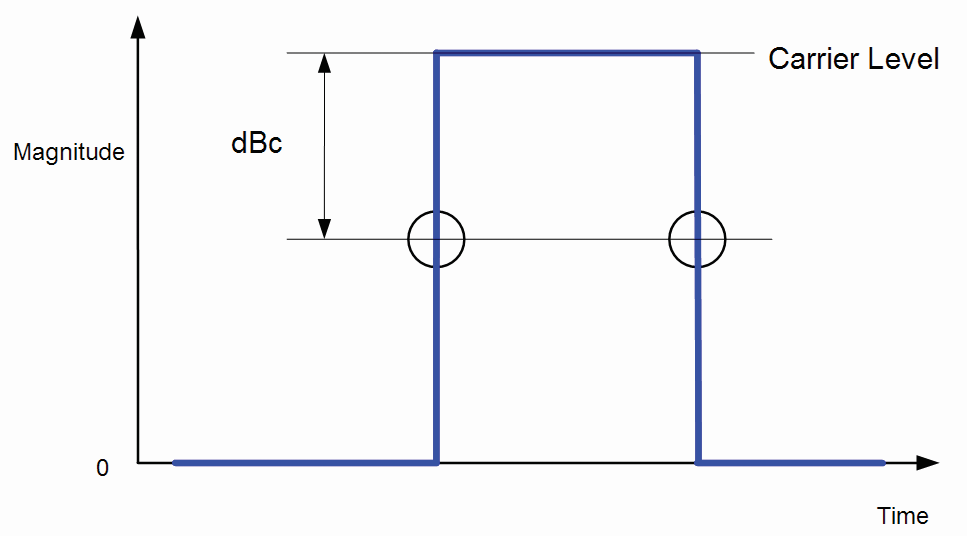
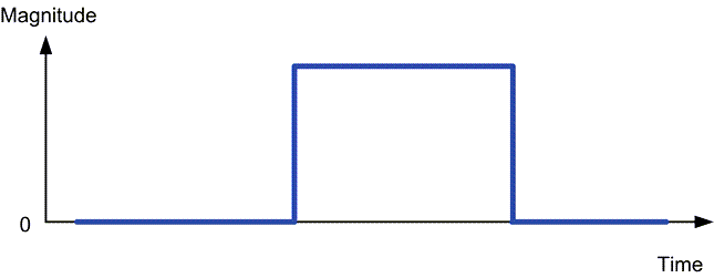
Figure 2. An idealized RF pulse.
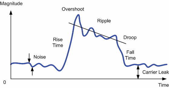
Figure 3. A real-world measured pulse can have many distortions that make rise/fall time measurements difficult.
Even with this flexibility, it is often not good enough. How the top of a pulse is measured can greatly affect the definition of transition time. If the top of the pulse is flat, then there is no problem (see Figure 2). But if the top of the pulse is tilted or has droop then there is a potential problem (see Figure 3). Suppose a pulse droops down by 20% over the duration of the pulse and the upper transition point is 90% of the highest part of the top. This pulse will have its rise time calculated correctly, but the fall time will be quite incorrect as the falling 90% point will be in the middle of the pulse due to the droop.
One method to address this problem is allowing the measurement to define the shape of the pulse. Drawing a best-fit line through the top of the pulse allows more realistic rise and fall time calculations. To prevent overshoot and ringing from defining this line, the fit should be biased towards the middle 50% of a pulse.
A measurement system should be able to modify any one of these parameters so that you can get the best measurements of your radar pulses. Tektronix Oscilloscopes and Real-Time Spectrum Analyzers with SignalVu-PC software make many of these options a simple click away.
To learn more about these parameters and the best ways to measure them, read our primer on Fundamentals of Radar Measurements. To see basic radar measurements with a spectrum analyzer in action, watch our Applications Engineer Alan Wolke walk through some common measurements.