Question :
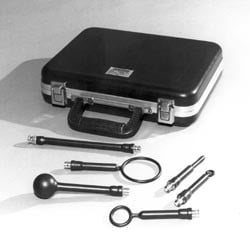
What is included in the Tektronix Near Field Probe kit (Tek p/n 119-4146-00) and what are they used for?
Answer :
The Tektronix 119-4146-00 Near Field Probe Set is intended to serve as a versatile aid for diagnostic testing of radiated emissions over a broad range of frequencies from below 100 kHz to above 1GHz. The probe set consist of three (3) magnetic field probes, two (2) electric field probes, 20 cm extension handle, and a custom carrying case.

Includes:
Model # Description Response Impedance
EM-6993 6 cm Loop H Field 50
EM-6994 3 cm Loop H Field 50
EM-6995 1 cm Loop H Field 50
EM-6996 3.6 cm Ball E Field 50
EM-6997 Stub E Field 50
The three magnetic field probes are electrically small (i.e. resonant frequency above 1GHz loops of varying sensitivities. The loops are wound within a balanced Faraday shield that reduces their response to electric fields to a negligible factor. Each successively larger loop increases sensitivity (independent of frequency) by approximately 12-155dB. Probes of reduce sensitivity may be of assistance in isolating a emission source more precisely.
The ball and stub comprise the two electric field probes. Each probe responds primarily to the electric field component and rejects the magnetic field component.
When making before-and-after measurements to determine the effectiveness of an attempted EMI solution, some care should be used to ensure that the measurements are repeatable. Of chief importance is the distance from the probe to the item under test. Even small changes in this spacing can yield large variations in amplitude. The E-field probes are also susceptible to measurement variations due to capacitive coupling to external objects such as equipment chassis, human bodies, large metal objects, etc. The H-field probes do not exhibit this effect.
The response of the E-field probes is essentially omni-directional. The response of the H-field probes is a figure-8 response, typical of a dipole. The primary pickup direction is broadside to the loop, with sharp notches in the pickup pattern in the plane of the loop.
Probe choice is determined by the type of signal under observation, signal strength, and the physical size of the area to be investigated. Comparison of the response to both H-field and E-field probes will provide the user with some idea as to the relative magnitude of the E-field and H-field of each component, thus providing a clue toward solving the emission problem. The larger probes provide increased sensitivity while the smaller probes permit a more precise location of the emission source.
The kit weight is 4.6 lbs (2.1 kg) with the probes inside and the case dimensions are 11” (28cm) x 12.75” (32.4 cm) x 4.75” (12.1 cm).
This FAQ Applies to:
Product Series: Máy hiện sóng miền hỗn hợp MDO3024 RSA3000 RSA5000B RSA6000
Product:
FAQ ID 64501
View all FAQs »
