Introduction
The source measure unit (SMU) is an instrument that can source current or voltage, and measure both current and voltage. The SMU is used for I-V characterization of a wide variety of devices and materials, and is designed to make very sensitive low current measurements while sourcing or sweeping a DC voltage. However, in test systems with long cables or other high capacitance test connections, some SMUs may not tolerate this capacitance on its outputs, resulting in noisy readings and/or oscillations.
The 4201-SMU Medium Power SMU and 4211-SMU High Power SMU (with the optional 4200-PA Preamp) make stable low current measurements, even in applications with high test connection capacitance. One example of this would be using very long triax cables to make connections to the device. The 4201-SMU and the 4211-SMU have increased maximum capacitance specifications, as compared to other sensitive SMUs. These SMUs are modules for the configurable Model 4200A-SCS Parameter Analyzer and are interactively controlled using the Clarius+ software.
This application note explains the maximum capacitance specifications of an SMU, and describes several applications on which the 4201-SMU and 4211-SMU enables you to make stable low current measurements. The example applications describe include the following: OLED pixel device testing on a flat panel display, transfer characteristics of a MOSFET using long cables, FET testing through a switch matrix, nano-FET I-V measurements on a chuck, and capacitor leakage measurements. Details on calculating test system capacitance is also provided in this application note.
Triax Cable Capacitance
When using an SMU to force voltage and measure low current, low noise triax cables are typically used for making connections between the SMU and the device under test. Even though other sources contribute to test connection capacitance, long triax cables are typically the most common source of additional capacitance on the output terminals. As shown in Figure 1, the triax cable has three conductors, and presents two different capacitances to consider during test system design using SMUs. The three conductors, as illustrated below, are the signal conductor (connected to Force HI), the inside shield (connected to Guard), and the outside shield (connected to Force LO). The guard eliminates leakage currents flowing through a cable’s insulator.

The capacitance/meter specifications of the triaxial cables used with the 4201-SMU and 4211-SMU are as follows:
- Between center pin (Force HI) and inside shield (guard): 98 pF/m
- Between inside shield (guard) and outside shield (Force LO): 330 pF/m
Note: When choosing triax cabling, use cables that are similar in specification to the low noise triax cables supplied with Keithley SMUs.

Maximum Capacitance Specifications of the SMU
The maximum capacitance specifications of the SMU are based on the capacitance between the shields of the triax connectors at the output of the SMU. Figure 2 illustrates the guard, shield and load capacitances connected to an SMU:
- Guard Capacitance: between Force HI (center pin) and Guard (inside shield)
- Shield Capacitance: between Guard (inside shield) and Force LO (outside shield)
- Load Capacitance: between Force HI (center pin) and Force LO (outside shield)
Table 1 lists the 4201-SMU and 4211-SMU maximum capacitance specifications and sources of test system capacitance.
| SMU Capacitance Specifications | Between SMU Terminals | 4201-SMU and 4211-SMU Specs | Source of System Capacitance |
| Maximum Load Capacitance | Force HI and Force LO | 100mA-1A ranges: 100 µF 100nA-10mA ranges: 10 µF 1nA-10nA preamp ranges: 10 µF 1pA-100pA preamp ranges: 1 µF |
DUT, coax cables, chuck |
| Maximum Guard Capacitance | Force HI and Guard | 5nF | Triax Cables and Connections |
| Maximum Shield Capacitance | Guard and Force LO | 10nF | Triax Cables and Connections |
TABLE 1. Capacitance specifications for 4201-SMU and 4211-SMU.
Calculating Test System Capacitance for Two and Four-Wire Measurements
When calculating the triax cable capacitance connected to each SMU, the cable length from Force HI and Sense HI to the device under test must be determined and then added together to get the total cable length. Then the capacitance/ meter specification of the triax cable is used to calculate the total capacitance. An example is shown below inFigure 3: the DUT is connected to SMU1 of the 4200A-SCS using two 15 m triax cables, Force and Sense, in a four-wire (or remote sense) configuration. Based on the capacitance/meter (pf/m) specification of the triax cable, the capacitance of two 15 m triax cables can be calculated from the following equations:
- Guard capacitance = 98 pF/m x 2 x 15 m = 2.9 nF
- Shield capacitance = 330 pF/m x 2 x 15 m = 9.9 nF

If a two-wire, or local sense, configuration was used to make connections then the cable capacitance can be calculated as:
- Guard capacitance = 98 pF/m x 15 m = 1.47 nF
- Shield capacitance = 330 pF/m x 15 m = 5 nF
In addition to the triax cables, other sources of test system capacitance include the patch panel, the switch matrix, the probe, the chuck and the DUT. These other sources of errors will be discussed in the example applications in the following sections.
Example Applications Requiring Increased Maximum Capacitance Specifications
The next few sections provide examples of sensitive low current applications, where the 4201-SMU and the 4211-SMU are used to make I-V measurements. These applications include: flat panel display testing, nMOSFET transfer characteristics using long cables, FET testing through a switch matrix, Id-Vg curves on a nano-FET, and capacitor leakage measurements.
OLED Pixel Device on Flat Panel Display
I-V curves of an OLED pixel device on a flat panel display are usually measured by connecting the SMUs, through a switch matrix, to an LCD probe station, using very long triax cables (typically 12-16m long). Figure 4 illustrates a typical flat panel display test configuration using the Keithley S500 Test System. The S500 is an automatic parameter tester that is customizable and commonly used to test flat panel displays. For the case illustrated, the SMUs in the S500 are connected through the switch matrix to the probe station, where the probe card connects the test signals to the DUTs on glass panels. Because very long cables are used for making connections, unstable low current measurements may result if proper measurement techniques and instruments are not used.
For example, Figure 5 shows instability in the saturation (orange curve) and linear (blue curve) for both I-V curves on an OLED device – when measured using a traditional SMU connected to the DUT with 16 m of triax cables. However, when these I-V measurements were repeated using the 4211-SMU on the drain terminal of the DUT, the I-V curves were stable as shown in Figure 6.


Transfer Characteristics of nMOSFET
The Id-Vg curves of an n-type MOSFET can be generated using two SMUs. One SMU sweeps the gate voltage and the other SMU measures the drain current. A circuit diagram of a typical test circuit is shown in Figure 7, where 20 m triax cables were used to connect the SMUs to the device terminals.

The transfer characteristics measured with two traditional SMUs, and with two 4211-SMUs are shown below in Figure 8. The blue curve (taken with two traditional SMUs) shows oscillations in the curve, especially at low current levels and when changing current ranges. The current measurements taken with two 4211-SMUs, the red curve, were very stable.

FET Testing Through a Switch Matrix
Device testing through a switch matrix can be challenging because additional cabling is required. Triax cables are used to connect the SMUs to the switch matrix, and from the switch matrix to the DUT. A typical circuit involving two SMUs connected through a switch matrix, using remote sense, is shown inFigure 9. Using remote sense (4-wire measurements) instead of local sense (2-wire measurements) requires two cables connected to each SMU, and will double the capacitance on the SMU output because the cables are in parallel.

In this case, the SMUs are connected to the Rows (input) of the switch matrix using two 2 m cables; and the Columns (output) of the switch matrix are connected to the patch panel using two 5 m cables. With an additional 1 m cable connected from the patch panel to the probe, the total triax cable length from one SMU to the DUT is:
Total Triax Cable Length from one SMU
(with remote sense) to the DUT = (2 x 2 m) + (2 x 5 m) + (1 m) = 15 m
In addition to the triax cabling, the switch matrix itself adds capacitance and may need to be included when calculating the total test system capacitance.
Dramatic improvements resulted when using two 4211- SMUs, compared to two traditional SMUs, for measuring the output characteristics of a FET device through a switch matrix. In this test one SMU was biasing a constant gate voltage, and the second SMU was sweeping a drain voltage and measuring the resulting drain current. The drain current vs. drain voltage curves were generated using two traditional SMUs (blue curve) and two 4211-SMUs (red curve), as shown in Figure 10. The traditional SMU measuring the drain current appears to oscillate while making nanoamp measurements (as shown in the blue curve). However, when the 4211-SMU measured the drain current of the FET through the switch matrix, the measurements were stable (as shown in the red curve).

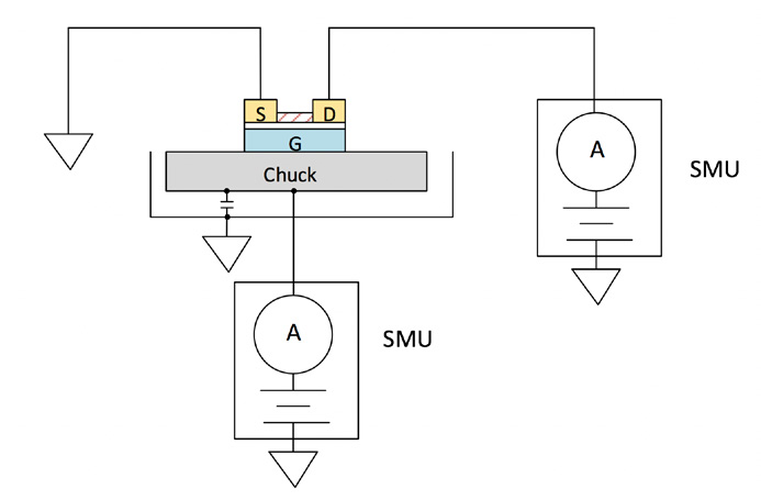
Nano-FET with Common Gate and Chuck Capacitance
Stable low current measurements can be made on nanoFETs and 2D FETs by using the 4201-SMU and 4211-SMU. These FETs, and other devices, sometime have a device terminal contacted through a probe station chuck to an SMU. A typical circuit diagram of a nano-FET test configuration is shown below in Figure 11. In this example, one SMU is connected to the drain terminal, and the other SMU is connected to the gate terminal through the chuck. The chuck can have capacitance as high as a few nano-Farads and can be verified by the probe station manufacturer. In some cases, it may be necessary to make contact to the gate using a conductive pad on top of the chuck.
The SMU connections to the chuck can be either coax or triax, depending on the probe station manufacturer. A coax chuck is represented in the test circuit as load capacitance, because the capacitance appears between Force HI and Force LO of the SMU. This is the case in the example illustrated. However, a chuck with triax cabling is represented as cable capacitance.
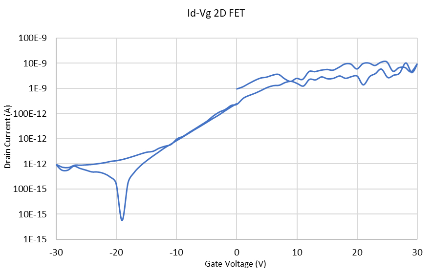
By using two traditional SMUs connected to the gate and drain of a 2DFET, a noisy Id-Vg hysteresis curve was generated as shown inFigure 12. However, when two 4211-SMUs were connected to the gate and drain of the same device, the resulting hysteresis curve was smooth and stable as shown in Figure 13.

Capacitor Leakage
Capacitor leakage is measured by applying a fixed voltage to the capacitor under test and measuring the resulting current. The leakage current will decay exponentially with time, so it’s usually necessary to apply the voltage for a known period before measuring the current. Depending on the device under test, the measured current is typically very small (usually <10nA). A circuit diagram for measuring capacitor leakage using an SMU is shown below inFigure 14. The series diode in the circuit is recommended to reduce measurement noise. For more detailed information on how source capacitance can affect the noise performance of a feedback ammeter, please refer to Section 2.3.3 Noise and Source Impedance of the Keithley 7th Edition Low Level Measurements Handbook.

Figure 15 shows a graph of leakage current vs. time of a 100nF capacitor measured with the 4201-SMU. Because of the increased maximum load capacitance specification, the 4201-SMU and 4211-SMU are more stable when measuring capacitor leakage, however the need for the series diode will depend on the insulation resistance and magnitude of the capacitor as well as the current measurement range. Some experimentation may be needed.

Conclusion
The Keithley 4201-SMU Medium Power SMU and 4211-SMU High Power SMU are ideal for sourcing voltage, and making very sensitive (<nA) low current measurements on devices and materials. These SMUs are especially beneficial for making stable low current measurements in test circuits with high test connection capacitance. They have increased maximum capacitance specifications, as compared to other sensitive SMUs.
In addition to using the appropriate SMU, using the proper techniques for making low current measurements is important. These techniques, such as shielding and guarding, are described in more detail in the Keithley Low Level Measurements Handbook, as well as in the application note, “Optimizing Low Current Measurements with the 4200A-SCS Parameter Analyzer”. These documents can be found at www.tek.com.
Find more valuable resources at TEK.COM
Copyright © Tektronix. All rights reserved. Tektronix products are covered by U.S. and foreign patents, issued and pending. Information in this publication supersedes that in all previously published material. Specification and price change privileges reserved. TEKTRONIX and TEK are registered trademarks of Tektronix, Inc. All other trade names referenced are the service marks, trademarks or registered trademarks of their respective companies.
100419 1KW-61609-0