DC Bench Power Supplies - 6 Things You Must Know
Bench power supplies have always been a staple of the test engineer’s bench. We use them every day and yet they are one of the most often overlooked instruments on the bench. With the right bench power supply and a good knowledge of its features and functions, you may be able to improve the speed and accuracy of your tests. The following is a list of the things you should know about the bench power supplies you use, as well as things to consider when looking for a new DC power supply for your bench.
1. Power Limits
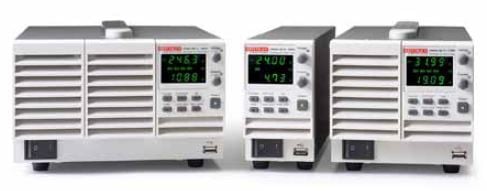
DC Power Supplies in a product family or group are typically differentiated by their maximum voltage and maximum current. In the Keithley bench power supply portfolio, the model number includes these specs (2260B-30-72 for example, has a maximum voltage of 30 V and a maximum current of 72 A). While this is helpful, the power limits of the supply are just as important. The above mentioned 2260B-30-72 bench power supply can supply up to 30 V or 72 A but it has a power limit of 720 W, so the supply wouldn’t be able to source 30 V at 72 A as it would be power limited.

Knowing the voltage set and the current that should result, or the voltage set and the resistance of the DUT, the power generated is given by the following:
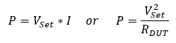
So long as the power calculated from these equations is lower than the power limit of the bench power supply, it should be able to operate normally. However, it is a good idea to read through the manual or datasheet of the power supply to ensure that the voltage and current of the test is valid for that instrument, as some power limits are not linear.
2. Constant Voltage (CV) and Constant Current (CC) Mode
Most bench power supplies have two operating modes, Constant Voltage (CV) and Constant Current (CC). In CV mode, the power supply will source a set voltage up to a set current limit. The power supply will source the voltage that is set so long as the resistance of the device-under-test (DUT) generates a current that is below the current limit. If the resistance of the device is low enough that it generates a current above the current limit, the power supply will clamp the output at that current limit and switch into constant current mode until the load resistance increases or the voltage is set to a lower value.
Operating a power supply in constant current mode can be a bit counter intuitive. Constant current mode doesn’t make the bench power supply into a current source, it only tells the power supply what behavior is expected at the output. By setting the current limit to the desired value, then setting the voltage to a value that would otherwise generate a current *higher* than the limit, the power supply will go into current limit and hold that constant current. This is calculated with Ohm’s Law. The voltage set should be greater than the current limit set multiplied by the resistances in the circuit (including the test leads, if being extra careful!)

3. Remote Sense Voltage Monitoring
For the most accurate voltage sourcing, use a bench power supply that comes equipped with remote sense. This is an extra set of terminals, usually found on the rear panel of the instrument, that is connected to an internal voltage monitor in the power supply. Typically, these will come with jumpers installed to the positive and negative output terminals. If these sense terminals are left open, the power supply will behave erratically as it has no means of monitoring the voltage it is sourcing.
Leaving the sense terminals connected to the output terminals is fine for most high resistance applications (RDUT > ~100 Ω) but for lower resistance loads this can become inaccurate. The power supply is sourcing voltage into the DUT as well as the test leads that are connecting the bench power supply to the DUT. Considering that most standard ~3 ft. test leads have a resistance of ~50 mΩ (~100 mΩ for a pair), there can be considerable voltage drop on the leads when using a low resistance DUT.
The equation for calculating the voltage at the DUT is below, using the resistance of the device and the resistance of the test leads, which can be found by inserting the leads into a DMM set to 2-wire Ω and connecting their tips.

For example, sourcing 10 V into a 10 Ω DUT with standard ~100 mΩ test leads would generate about 9.901 V at the DUT, with the additional ~0.099 V being dropped along the two test leads (about 1% error). If that DUT was 1 Ω, only 9.091 V would appear at the device, nearly 10% lower than the expected value.
Connecting the remote sense lines on either side of the DUT, the bench power supply can now measure the voltage drop across the DUT *only*. This allows the power supply to increase its voltage at the output terminals and compensate for the voltage drop along the test leads until the voltage set matches the voltage it is measuring. The amount the test lead voltage drop the supply can compensate can usually be found in the datasheet.
4. Parallel and Series Operation
For tests requiring more power, parallel and series operation can be used to increase the available voltage or current. This is a feature that most bench power supplies support to some degree. The higher power multi-channel 2230G series of Keithley bench power supplies, for example, natively support parallel and series using 2 of the channels on the power supply to double the current or voltage available. That series of power supplies has a setting specifically for combining outputs that allows the power supply to read the correct voltage and current as though it were operating as a single supply. However, even if this “smart output combining” feature is not available on a power supply, most support parallel and series operation (double-check the manual to be safe).
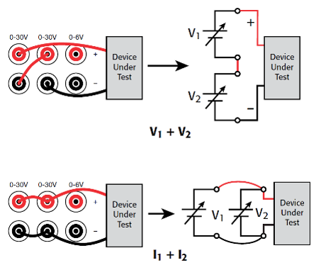
To increase the voltage available, connect the bench power supplies in series. This is achieved by connecting the positive output of one power supply to the negative output of another, then connecting the remaining positive and negative outputs to the DUT.
To increase the current available, connect the bench power supplies in parallel. This is achieved by connecting both positive outputs to one terminal of the DUT and both negative outputs to the other terminal of the DUT.
Refer to the power supply manual for instructions on using remote sense, if using that feature while combining outputs. It may not be possible in certain configurations or if using different supplies.

5. Test Sequences/Output Timers
Manually setting voltage values and current limits can be a waste of valuable time when running long or complex tests with a power supply. Thankfully, most bench power supplies come with a test sequence feature or at least some form of output timing. This is a simple way to control a complex test without having to spend time adjusting settings on the power supply.
Setting up test sequences will be very dependent on the manufacturer and product family of bench power supply used, but they will typically operate as either a sequence of values or a timer for a value that is set.
If a power supply supports test sequences, it can take pre-programmed voltage values, current limit values and time per step. This will allow the power supply to generate complex tests and allow the operator more time to focus on getting quality measurements.
6. Response Time
For tests requiring rapidly changing voltages or loads, response time is critical. This spec will detail how long it takes the bench power supply to ramp up or ramp down to a set voltage. Keep in mind that this spec will often vary with load, so it is a good idea to check any notes included with the specification that detail the load used when the spec was generated.
This specification will often come in a few parts, rise time, fall time and transient recovery time. Rise time details the typical amount of time the power supply will take to rise to a certain value, this is given as the time taken for the power supply to go from 10% of the value to 90% of the value. Fall time is similar, though in reverse, this details the amount of time taken to go from 90% of the value to 10%.
Transient recovery time is a more complex specification. This is usually described with a few parameters, the voltage settling band, the transient recovery time and the step change in load current. For example, the Keithley 2200 series bench power supplies have the following Load Transient Recovery Time spec, “<400 μs to within 75 mV following a change from 0.1 A to 1A.” This means that, if the current load was to change from 0.1 A to 1 A (step change in load current), the power supply will get to within 75 mV of the set voltage (voltage settling band) in less than 400 μs (the transient recovery time).
These 6 important features/specifications of bench power supplies should be considered when using any power supply. They can save time and effort or make tests more accurate. As always, feel free to contact the Keithley Technical Support team if you need help choosing a new bench power supply or getting the most out of your current Keithley bench power supply!