Document # PA-961A
Introduction
The Keithley Instruments Model 2600-STD-RES 1GΩ resistor is a precision guarded resistance standard that may be used as a high-resistance physical constant to calibrate low-current instruments. An accurate current measurement may be made from the physical constants of resistance and voltage if the initial value of these constants is accurately determined.
The Model 2600-STD-RES resistor is recommended for calibrating the lowest current ranges of Keithley Instruments Models 2635 and 2636. Similar current-sourcing and measuring instruments and other Series 2600 System SourceMeters® can also be calibrated in part using the Model 2600-STD-RES and similar procedures.
The following table shows the Model 2600-STD-RES specifications.
Model 2600-STD-RES specifications
| Specification | Value |
| Maximum input voltage | 200VDC peak |
| Voltage coefficient | 0.2 PPM/V |
| Dimensions | 20mm x 57mm x 114mm (0.8in x 2.25in x 4.5in) |
| Connectors | Two 3-lug triaxial |
| Weight | 180g (6.3 oz) |
| Operating environment | 23°C (73°F), 30% to 60% relative humidity |
| Nominal value of standard | 1GΩ |
| Maximum deviation from nominal | ±1% |
| Accuracy of characterization | <100 PPM |
| Temperature coefficient | <10 PPM / °C |
| One-year stability | 150 PPM |
Model 2600-STD-RES shipment contents
| Quantity | Description |
| 1 | Model 2600-STD-RES 1GΩ precision standard |
| 1 | Triaxial to banana cable pair (part number 2600-STD-RES-070) |
| 2 | Triaxial to triaxial cables (part number 7078-TRX-3) |
| 2 | Triaxial 3-slot cap (part number CAP-31) |
| 1 | Support bracket (included for optional rack mounting of the 2600-STD-RES) |
| 1 | Captive panel screw (included for optional rack mounting of the 2600-STD-RES) |
General testing information
The Model 2600-STD-RES standard has three key specifications that are critical to minimizing the overall resistance uncertainty:
- Low temperature coefficient of resistance.
- Long-term stability.
- Low calibration uncertainty (when calibrated by Keithley Instruments).
In addition to resistor standard errors, the following measurement errors must be considered:
- Voltage source uncertainty and noise.
- Voltage measurement standard uncertainty and noise.
- Current measurement noise of device being calibrated.
- Settling time required for full accuracy measurement of a low-current source.
The following guidelines should be followed when conducting low-current measurements:
- Avoid temperature variations of standards and devices under test.
- Avoid vibrations, which may cause triboelectric effects.
- Average readings using a long analog-to-digital converter (A/D) aperture and an appropriate math filter such as median filtering to decrease noise effects and allow settling.
- Be aware of errors due to noise that may not be removed by filtering.
- Consider all standard measurement uncertainties and instrument setup.
- Avoid excessive external electrical events and use guarded triaxial cables. Noisy readings are typically caused by a noisy source or improper use of the guard.
- Always verify a calibration of a low current with a final verification measurement step.
WARNING
The maximum common-mode voltage (voltage between LO and chassis ground) is 250VDC. Exceeding this value may cause a break down in insulation, creating a shock hazard. The Input/Output terminals of the SourceMeters® are rated for connection to circuits rated Installation Category I only, with transients rated less than 1500V peak. Do not connect the Series 2600 terminals to CAT II, CAT III, or CAT IV circuits. Connection of the SourceMeter® terminals to circuits higher than CAT I can cause damage to the equipment or expose the operator to hazardous voltage.
Hazardous voltages may be present on the output and guard terminals. To prevent electrical shock that could cause injury or death, NEVER make or break connections to the Series 2600 while the unit is on. Power off the equipment from the front panel or disconnect the main power cord from the rear of the Series 2600 before handling cables connected to the outputs. Putting the equipment into standby mode does not guarantee the outputs are not powered if a hardware or software fault occurs.
Accuracy characterization of source-measure unit (SMU) low current ranges
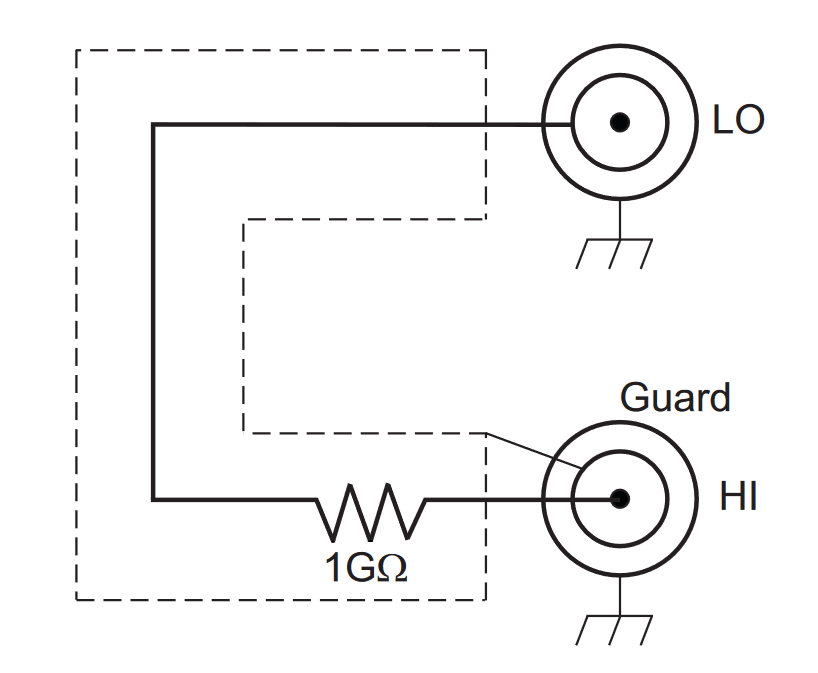
The 100pA through 100nA current ranges require a guarded current measurement to prevent errors such as leakage from external error sources. A suitably guarded, characterized 1GΩ resistance standard (such as the Model 2600-STD-RES) and an accurate digital multimeter (DMM) such as the Keithley Model 2002 (or equivalent) can accurately characterize the lower ranges. The steps involve forcing a characterized voltage across the 1GΩ resistor and comparing source measure unit (SMU) measured results against the standard resistance and derived current.
Performance verification general overview
Here is a summary of how low-current range performance is characterized. The specific steps for characterization and calibration are found in the next section.
Step 1: Characterize appropriate ± voltage source value
±100.00mV 1.5A compliance 100pA range
±1.0000V 1.5A compliance 1nA range
±10.000V 1.5A compliance 10nA range
±100.00V 100mA compliance 100nA range
Step 2: Characterize desired SMU measure current ranges
- Measure the source voltage using an accurate DMM.
- Determine the Model 2635/2636’s actual zero current by disconnecting the cables to the DMM and capping the Model 2635/2636 terminals so that no current can flow (this is the offset of the current measurement).
- Connect the Model 2600-STD-RES. The source voltage (from step a, above) should be nearly perfect so that current = voltage/resistance. This provides information for the gain error (note that this value may vary from what the instrument is actually reporting).
- Measure the current with the Model 2635/2636. Average the readings using a long A/D aperture and an appropriate math filter (such as median filtering) to decrease noise effects and to allow settling. Refer to the Series 2600 System SourceMeter® Reference Manual for more information on setting the A/D aperture.
Step 3: Characterize desired SMU source current ranges
- Source a full-scale current value and a value near zero into the Model 2600-STD-RES.
- Using the previously-obtained measurement values, determine the SMU source deviation from actual values measured on the SMU.
Model 2635/2636 SMU low-current performance testing
Set up the instrument as outlined in the performance verification section of the Series 2600 System SourceMeter® Reference Manual. The manual describes proper warm-up period, environmental conditions, verification limits, and test equipment.
Note
The low-current range verification and calibration process should be performed using Keithley Instruments factory scripts. See your instrument’s documentation for more information on calibrating the instrument. Factory test scripts are available for download at tek.com/keithley.
Instrument settings
DMM settings are instrument-specific. Models 2635 and 2636 have front-panel settings that may be more efficiently set by using Instrument Command Library (ICL) commands. All calibration commands are ICL only. Predefined test scripts should be downloaded or new scripts can be created using Keithley Instruments Test Script Builder. Test scripts and Test Script Builder are available on the Keithley Instruments website at www.keithley.com.
Be sure to take time to review the script and embedded script comments for additional details on the test procedure before beginning verification and calibration.
Instrument setup
- Connect the Model 2635/2636 to a host PC and open the Test Script Builder program (or equivalent terminal emulator) on the host PC. If you are using Test Script Builder, you can connect the host PC and the Model 2635/2636 using any of the following methods:
- GPIB
- Serial
- RS-232
- Install the Model 2635/2636 safety interlock as outlined in the Series 2600 System SourceMeter® Reference Manual. Failure to install the interlock can result in inaccurate test results or cause the test sequence to abort.
- Load the test script into the Model 2635/2636 as outlined in the Series 2600 System SourceMeter® Reference Manual. If you are not using Test Script Builder, refer to your terminal emulator’s documentation for information on loading test scripts.
- Set the verification DMM to volts range and for 10 power line cycles (PLC). Filter readings by setting the DMM to a 10-reading moving average.
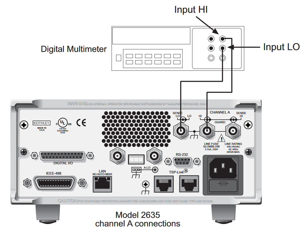
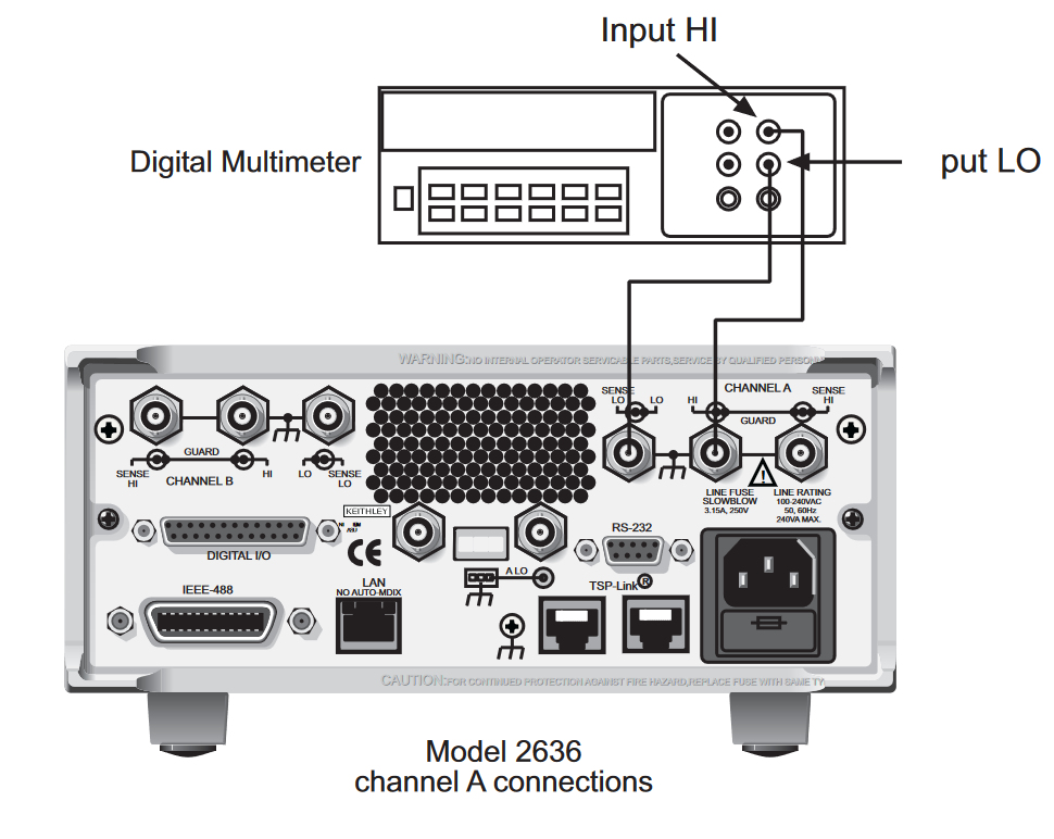
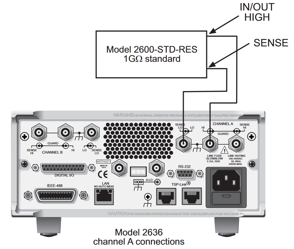
- Using the Model 2600-STD-RES-070 cables, connect the Model 2635/2636 to the DMM as shown in the following figures.
- Set the DMM to display the maximum number of digits.
Low-current range test procedure
Note: When using Keithley Instruments test scripts, the verification and calibration adjustment procedures are both performed during this test. For performance verification only, perform the tests but do not save the calibration information at the end of the procedure. This will preserve the current calibration constants and show you the Model 2635/2636’s current calibration settings.
- Load the test script into the Model 2635/2636 using a host PC running Test Script Builder or a terminal emulator program. Notes in the script programming indicate the program name and version.
- After loading the test script into the Model 2635/2636, run the script using Test Script Builder or the terminal emulator on the host PC by typing the name of the program followed by (). The Model 2635/2636 immediately initiates the calibration sequence.
Note: After running the script from the host PC using Test Script Builder or a terminal emulator, the rest of the calibration procedure will be performed using the front panel as described below. - Enter the resistor value using the navigation wheel and press the ENTER key. The resistor value is indicated on the Model 2600-STD-RES calibration certificate (included).
- Rotate the navigation wheel to select the channel being tested and press the ENTER key.
- The front-panel display prompts you to connect the test cables to the DMM:
Connect Triax to DMM
Connect the 2635/2636 to the DMM as shown in step 4 of Instrument Setup, above. Press any key to continue. - The front-panel display will ask you if you want to calibrate and verify the 100 pA range:
Cal/ver 100pA Range?
Select yes and press the ENTER key to verify and calibrate the 100 pA range. Select no and press the ENTER key to go to the next test range (1nA). - The Model 2635/2636 outputs a voltage to the DMM. Enter the positive voltage value read by the DMM using the navigation wheel. Press the ENTER key after entering the value. Do the same for the negative voltage value.
- While the unit settles, the front-panel display shows the following message:
Cal/Verify Continue

    Unit settling please wait
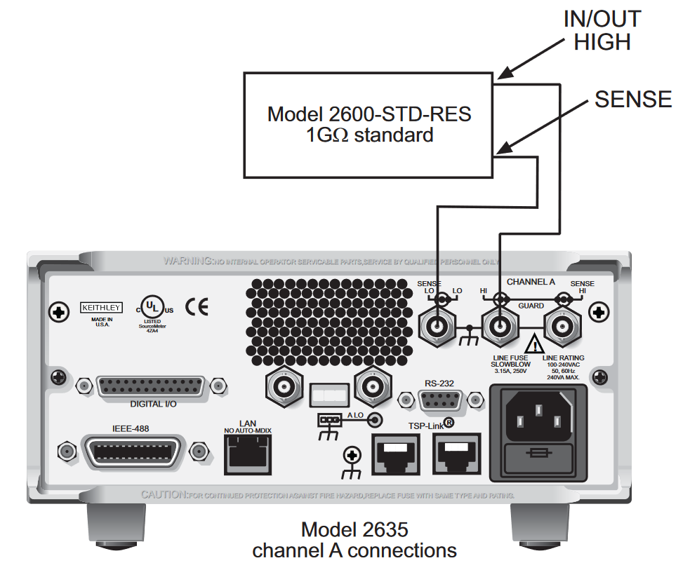
This may take several moments. Do not touch any of the front-panel controls during this period or the test will be aborted. - Once settling is complete, the front-panel display will prompt you to connect the Model 2600-STD-RES using the Model 7078-TRX-3 cables as shown in the following figures:
Connect R Standard
After the Model 2600-STD-RES is connected, press any key to continue. - Once the Model 2600-STD-RES is connected, the Model 2635/2636 calibrates itself. The front panel display shows the following message:
Cal/Verify Continue

    Unit settling please wait
This may take several minutes. Do not touch any of the front panel controls during this period or the test will be aborted.
- Once the Model 2635/2636 has completed the calibration for that range, the resulting SMU measurements for that range are displayed on the host PC by Test Script Builder or the terminal emulator. Record these readings and compare them to the specifications for each range found in Table 3. Note that the information in Table 3 is based on 90% of full-scale values (see the Series 2600 System SourceMeter® Reference Manual for more information).
- After completing the calibration of each range, the front panel display asks if you wish to calibrate the next range. Repeat steps 2 through 10 for all ranges.
- When the calibration for all selected channels is complete, the front panel display asks if you wish to save calibration changes. Select yes or no by turning the navigation wheel, then press the ENTER key.
NOTE: Selecting no will not save the correction factors. All calibration adjustments will be lost at the next system boot. - If you selected yes when prompted to save calibration changes, follow the front panel display prompts to enter the current calibration date and the next calibration date using the navigation wheel and the ENTER key.
- Press the EXIT key to exit calibration mode after the front panel display shows the following message:
- Once calibration is complete, run the procedure a second time to verify proper calibration results.
NOTE: After listing the SMU measurements in step 11, the front panel display of the Model 2635/2636 may continue to display the following message for several more minutes. This is normal.
Cal/Verify Continue

    Unit settling please wait
Model 2635/2636 current measurement accuracy limits
| Source and measure range | Source current | Current reading limits (1 year 18°C to 28°C) |
| 100pA | 90.000pA | 89.7850 to 90.2150pA |
| 1nA | 0.90000nA | 0.89841 to 0.90159nA |
| 10nA | 9.0000nA | 8.9835 to 9.0165nA |
| 100nA | 90.0000nA | 89.9060 to 90.0940nA |
Cal complete!
Find more valuable resources at TEK.COM
Copyright © Tektronix. All rights reserved. Tektronix products are covered by U.S. and foreign patents, issued and pending. Information in this publication supersedes that in all previously published material. Specification and price change privileges reserved. TEKTRONIX and TEK are registered trademarks of Tektronix, Inc. All other trade names referenced are the service marks, trademarks or registered trademarks of their respective companies.
PA-961 June 2008