Introduction
Wide band gap devices are well known in power electronics technologies. Silicon Carbide (SiC) is a promising material which has advantages in gain efficiency and power density to achieve high voltage and high current in comparison to silicon-based devices. The threshold voltage (Vt) is a key device characterization parameter of the power MOSFET (Metal Oxide Semiconductor Field Effect Transistor). But threshold voltage measurements with a SiC MOSFET have a reliability issue where the threshold voltage can change depending on the previous gate bias. A hysteresis behavior is shown in the gate upward sweep versus the gate reverse sweep. This threshold voltage variation can also impact other device characteristics such as leakage current and on-state resistance (RdsOn). JEDEC standard JEP183A introduced guidelines for measuring the threshold voltage (Vt) of an N-channel vertical structure SiC MOSFET device.
This application note provides the SiC device hysteresis details of a SiC MOSFET and proposes how to make reliable measurements for the threshold voltage in accordance with the JEDEC standard. Keithley provides a variety of SourceMeter® units (SMUs) to characterize power MOSFET devices including the threshold voltage test. This application note introduces an example of a Test Script Processor (TSP®) script to test the threshold voltage standard using a 2636B SourceMeter.
Keithley also produces High Power SourceMeter units (SMUs) to characterize power MOSFETs. The 2657A High Power System SourceMeter Instrument can source up to 3 kV, and the 2651A can source up to 50 A pulsing along with the 8010 test fixture. Keithley’s ACS software and KickStart software offer automated setup and execution of the I-V characterization tests for power MOSFETs.
SiC Hysteresis in the Threshold Voltage Measurement
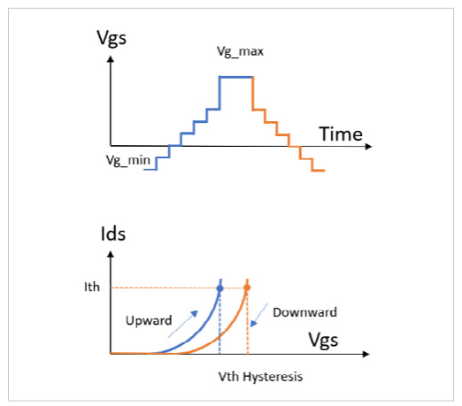
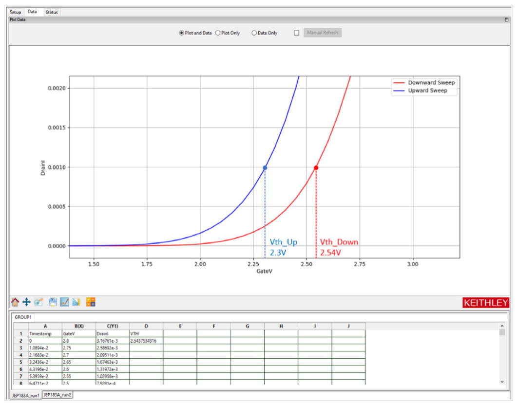
One of the methods for measuring threshold voltage (Vt) is sweeping the gate voltage and measuring the drain current at a fixed voltage bias. There are several ways to define the threshold voltage from the resulting transfer curve measurement (Vg-Id). The most common is that when the drain current hits a certain level, the gate voltage is the threshold voltage at that current level. However, SiC devices have different characteristics between the upward (negative to positive voltage) and downward (positive to negative voltage) directions. As shown in Figure 1, a hysteresis is observed in the Vg-Id data, and the threshold voltage is different in the two cases depending on the starting voltage bias of the gate.
Interface Between SiC and Gate Oxide
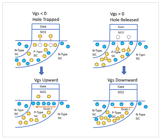
Hole charge trapping is the major cause of threshold voltage hyteresis between upward and downward direction sweeps. When a negative voltage is applied at the gate terminal, many holes, which are majority carriers with positive charges in the SiC layer, are forced to move into the gate oxide interface. Some of them become trapped there by the negative gate bias shown in top left of Figure 2. When the gate voltage sweep is performed upward, the positive gate bias pulls some minority carriers as electrons into the SiC layer to make the drain current flow as shown. In addition, the previously trapped hole charges attract more electrons as shown in bottom left of Figure 2. These trapped charges are known to cause higher current flow.
On the other hand, when a positive voltage is applied at the gate terminal, electrons acting as minority carriers move to the interface layer and the positive gate bias pushes the previously trapped positive charges from the silicon oxide layer to the SiC layer shown in the top right of Figure 2. When the gate voltage sweep is performed downward, electrons driven by the gate voltage contributes to making the drain current level lower than the upward direction current.
SiC Hysteresis Observed
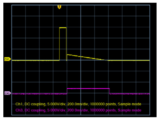
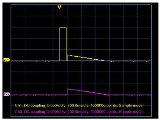
Figure 3 shows the result of drain current hysteresis verses gate voltage in an oscilloscope time domain, tested with a commercially available SiC MOSFET device using 1200 V 32 A power. There are two steps for this test. The first is upward sweeping with a negative pre-conditioning pulse on the gate and the second is downward sweeping with a positive pre-conditioning pulse on the gate. The first half of the test starts with a gate voltage pulse of -3 V, then increases the gate voltage (yellow) while keeping the drain voltage (purple) fixed. The drain current (green) begins with low level leakage and ramps up as the gate bias increases. The second half starts with a maximum positive gate bias +15 V, then the gate voltage sweeps in the downward direction. The drain current decreases from the peak level as the gate bias decreases. The difference of drain current level between the two directions is observed even in the time domain capture. That difference shows hysteresis in the Vg-Id curve and the threshold voltage gap.
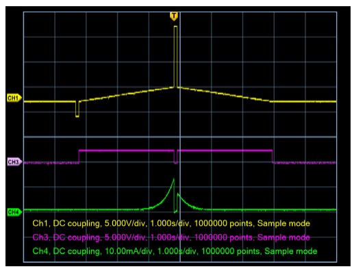
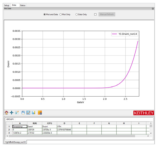
Figure 4 shows the result of sweeping gate bias in both directions in the ACS software. At 1 mA drain current, the gate voltage has a 0.24 V gap in both directions. This threshold voltage variance could affect the leakage current and on-state resistance (RdsOn). The threshold voltage could also have an impact on long term instability in reliability tests. The JEP183A standard proposed a new guideline to measure consistent measurements for the threshold voltage. The guideline is to add a pre-conditioning pulse prior to the gate sweep measurement to release any trapped hole charges from the silicon oxide interface and sweep downward. The JEP183A standard also proposed three different methods of SiC threshold measurement. Keithley SMUs and software can support all three of these methods.Keithley TSP scripts can be useful in any application and can be embedded in ACS-Standard and ACS-BASIC software, giving the user the benefit of ACS’s graphical interface so code modification is not necessary. TSP allows us to program the SMUs to complete both the pre-conditioning pulse and sweep without complex programming for synchronization.
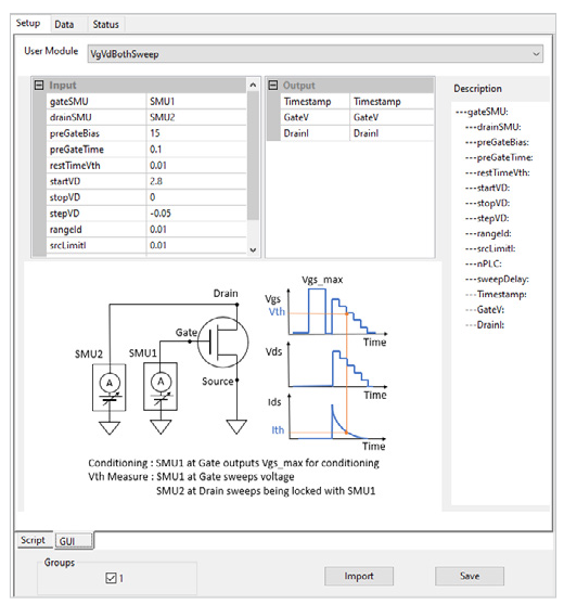
Sweeping Bias on Gate and with Fixed Drain
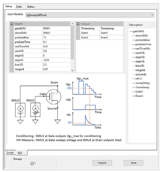
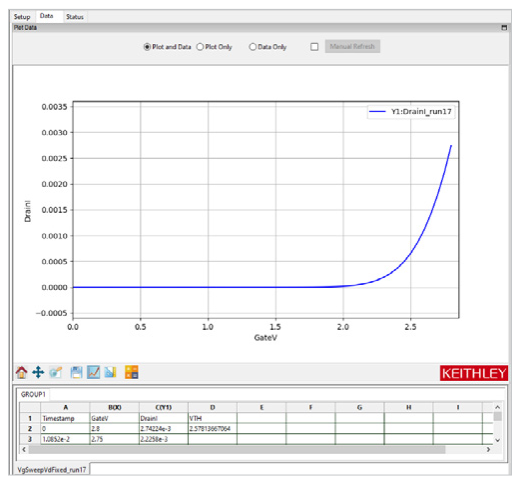
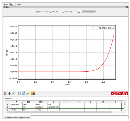
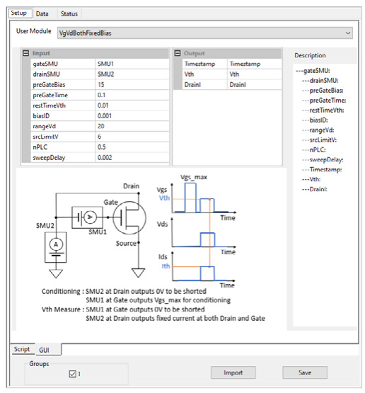
The first method is to set the gate bias to be swept and drain bias to be fixed. The test script is embedded in ACS software in an STM (Script Test Module), and the setup is shown in Figure 5. The waveforms in Figure 6 are shown to be identical to what is programed in the software. Two SMU channels are connected to the gate and drain terminals separately. If the power SiC device is a TO-247 type package, the 8010 Keithley High Power Device Test Fixture would be the best fit to connect to the device. To comply to the standard, a pre-conditioning pulse should be applied on the gate terminal while keeping the drain and source terminals grounded. As shown in Figure 7, the test result should appear like a typical transfer curve (Vg-Id). The advantage of ACS software is that it can supply the threshold voltage calculation from the raw I-V data. For the device used in this example, the gate voltage is 2.57 V at 1 mA drain current.
Sweeping Bias on Gate and Drain
The second method is to set both the gate and drain bias to be swept. To achieve this, there are three options to configure the instrumentation for the measurement.
- Set up a single SMU and use a switch matrix to route the SMU to the desired terminals for the preconditiong pulse and the sweep
- Set up two separate SMUs to sweep the gate and drain
- Set up one SMU to perform the sweep and a second SMU to perform the preconditioning pulse
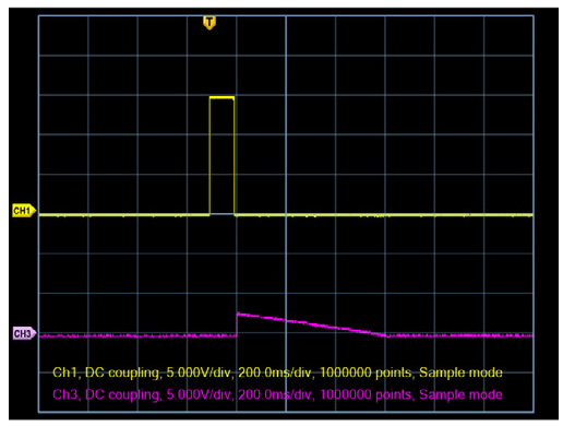
This application note will focus on options two and three. Figure 8 shows the configuration for option two, where two SMUs are connected to the gate and drain terminals separately. The waveforms in Figure 9 are identical to what is programed in the software. As the standard proposed, a pre-conditioning pulse should be applied on the gate terminal while keeping the other terminals grounded. The gate SMU and the drain SMU should work in synchronization to ensure the gate and drain are at the same potential. ACS software handles configuring the model. As shown in Figure 10, the test result should look like a typical transfer curve (Vg-Id). In this case, the gate voltage is 2.57 V at 1 mA drain current. The value in this test may be a bit different in comparison to the first test method where only the gate is swept, because the conditions are not identical. However, this device clearly has the same threshold voltage as in the first case.
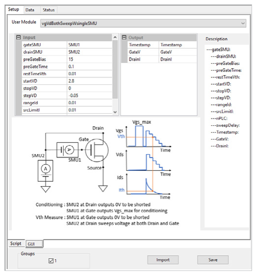
The previous set up requires both SMUs to be tightly synchronized for correct results. The benefit of the first setup is that the same SMU sweep is routed to each of the terminals, ensuring that the terminals receive the same input. However, this involves additional programming for the matrix control and additional costly hardware. The second setup can be modifed to reduce the synchronization requirements by using only one of the SMUs to perform the sweep, and the second SMU to perform the preconditioning pulse only. We can achieve this by connecting the low of the gate SMU to the high terminal of the drain SMU as shown in Figure 11.
During the preconditiong pulse, the drain connected SMU is set to zero volts, acting as a short to low. After the pulse, the drain SMU performs the sweep measurement and the gate SMU must source a zero voltage bias to create a short circuit from the drain SMU to the gate terminal. Then the drain and the gate have the same bias from the single drain SMU. Figure 12 shows the actual waveforms for each SMU. Figure 13 shows that the test result would be like a typical transfer curve (Vg-Id). The gate voltage is 2.57 V at 1 mA drain current. This value is exactly the same as the threshold voltage as the previous set up in which two separate SMUs performed the sweep.
Fixed Current Bias on Both Gate and Drain
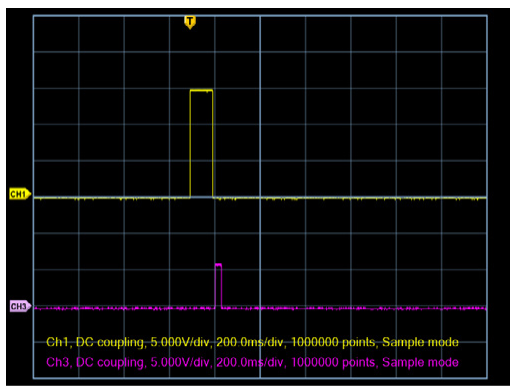
The third method in the JEP183A standard is to set a fixed current bias for both the gate and the drain. This method uses the same instrument configuration as the third option of the second method. Two SMUs are connected, the first to the gate and the second to the drain with the LO terminal of the gate tied to the HI terminal of the drain as shown in Figure 14. During the preconditiong pulse, the drain connected SMU is set to zero volts to short the low to the source. When the drain SMU performs the threshold voltage measurement, the gate SMU must source a zero voltage bias to create a short circuit from the drain SMU to the gate terminal. The gate and the drain must have the same fixed current applied. Alternatively, the same effect could be achieved by connecting an external switch system to route the SMU to the proper terminals during the preconditioning pulse and then the current bias. This can add additional complexity to the code and the connections, which is why this method has an advantage. No external switch matrix is needed to source the same current to the gate and drain.
The actual waveforms in Figure 15 are shown to be identical to what is programed in the software. This third method cannot provide a typical transfer curve (Vg-Id) but generates the threshold voltage directly via a voltage measurement at the fixed drain current. This example results in a threshold voltage of 2.57 V at 1 mA drain current which is in agreement with all the other test case results.
Conclusion
Keithley provides SourceMeter instruments and software to make the SiC MOSFET Vt measurement that the JEP183A standard proposed. A Keithley TSP script module can be used in any application and embedded in ACS software to use with the convenience of data visualization. To make the gate and the drain terminal short with a single channel SMU, an external switching system is required, or an additional SMU is necessary. But one SMU with two channels can provide the SiC threshold voltage solution without any additional switching or SMU instruments.
Appendix: TSP Code for Vt Measurements
--[[
################################################################################
Script File: SiC_Vth_Measurement.tsp
******************************************************************************************************************
*** Copyright Tektronix, Inc. ***
*** See www.tek.com/sample-license for licensing terms. ***
******************************************************************************************************************
Description:
This script is example code, which creates (and subsequently calls) a
single function that can be used with the Model 2636B SourceMeter unit
to make new threshold voltage measurement. There are three different methods
are introduced as the JEDEC standard proposed. All the measurements include
conditioning pulse prior to the execution. Upon completion, the data is
printed to the Test Script Builder Instrument Console in a format that is
suitable for copying and pasting into Microsoft Excel for graphing and
analysis.
Required Equipment: 1 Model 2636B System SourceMeter instrument
Note: The function does not perform any error checking. It is the user's
responsibility to specify settings that are compatible with the
instrument model being used, and with its power envelope.
Note: It is the user's responsibility to follow all safety guidelines given in
the instrument's Reference Manual. This is especially critical if
voltages in excess of 42VDC will be present in the test circuits. Such
voltage levels are hazardous.
Function created by this script:
For sweeping gate voltage and fixing drain voltage
* newVTH = newVthSiC_JEP183()
* newVTH.vgSweepVdFixed(15,100e-3,10e-3,2.8,0, -0.05,2.5,1e-3, 0.1, 0.5, 0.002)
For sweeping both gate voltage and drain voltage
* newVTH = newVthSiC_JEP183()
* newVTH.vgVdBothSweep(15, 100e-3, 10e-3, 2.8, 0, -0.05, 10e-3, 7e-3, 0.1, 0.002)
For sweeping both gate voltage and drain voltage with single SMU
* newVTH = newVthSiC_JEP183()
* newVTH.vgVdBothSweepWsingleSMU(15, 100e-3, 10e-3, 2.8, 0, -0.05, 10e-3, 7e-3, 0.1,0.002)
For fixing both gate current and drain current
* newVTH = newVthSiC_JEP183()
* newVTH.vgVdBothFixedBias(-4, 100e-3, 10e-3, 5e-3, 20, 5, 1, 50e-3)
################################################################################
--]]
function newVthSiC_JEP183()
local self = { }
local function initSMU()
local srcRangeI = 0.1
local srcRangeV = 20
local srcLimitI = 0.1
local srcLimitV = 20
local measRangeI = 0.1
local measRangeV = 20
local nPLC = 0.1
reset()
setGateAutoSourceRangeI(0)
setGateAutoSourceRangeV(0)
setGateAutoMeasureRangeI(0)
setGateAutoMeasureRangeV(0)
setGateSourceSettling(128)
setGateMeasAutoZero(1)
setGateSrcFunction(1)
setGateSrcRangeV(srcRangeV)
setGateSrcLimitI(srcLimitI)
setGateMeasRangeI(measRangeI)
setGateSrcRangeI(srcRangeI)
setGateSrcLimitV(srcLimitV)
setGateMeasRangeV(measRangeV)
setGateMeasNPLC(nPLC)
setDrainAutoSourceRangeI(0)
setDrainAutoSourceRangeV(0)
setDrainAutoMeasureRangeI(1)
setDrainAutoMeasureRangeV(0)
setDrainSourceSettling(128)
setDrainMeasAutoZero(1)
setDrainSrcFunction(1)
setDrainSrcRangeV(srcRangeV)
setDrainSrcLimitI(srcLimitI)
setDrainMeasRangeI(measRangeI)
setDrainSrcRangeI(srcRangeI)
setDrainSrcLimitV(srcLimitV)
setDrainMeasRangeV(measRangeV)
setDrainMeasNPLC(nPLC)
end
function self.vgSweepVdFixed(preGateBias, preGateTime, breakTimeVth,
startVG,stopVG,stepVG,biasVD,rangeId,srcLimitI,nPLC,sweepDelay)
setDrainMeasRangeI(rangeId)
drainBuffer = smub.nvbuffer1
drainBuffer.clear()
drainBuffer.appendmode = 1
drainBuffer.collecttimestamps = 1
local steps
steps = math.ceil((stopVG - startVG)/stepVG) + 1
local biasV = {}
setDrainMeasNPLC(nPLC)
setDrainSrcLimitI(srcLimitI)
setDrainSourceDelay(0)
setDrainMeasDelay(0)
setGatePowerOnOff(1)
setDrainPowerOnOff(1)
setGateSrcLevelV(preGateBias)
delay(preGateTime)
setGateSrcLevelV(0)
delay(breakTimeVth)
setDrainSrcLevelV(biasVD)
for index = 1,steps do
biasV[index] = startVG + (stepVG*(index-1))
setGateSrcLevelV(biasV[index])
delay(sweepDelay)
smub.measure.i(drainBuffer)
end
setGatePowerOnOff(0)
setDrainPowerOnOff(0)
print("No\tTime\tGateV\tDrainI")
for index=1,drainBuffer.n do
print(index, drainBuffer.timestamps[index],biasV[index],drainBuffer[index])
end
initSMU()
end
function self.vgVdBothSweep(preGateBias, preGateTime, breakTimeVth, startVD,stopVD,stepVD,
rangeId, srcLimitI,nPLC,sweepDelay)
setDrainMeasRangeV(rangeId)
drainIBuffer = smub.nvbuffer1
drainIBuffer.clear()
drainIBuffer.appendmode = 1
drainIBuffer.collecttimestamps = 1
drainVBuffer = smub.nvbuffer2
drainVBuffer.clear()
drainVBuffer.appendmode = 1
drainVBuffer.collecttimestamps = 1
local steps
steps = math.ceil((stopVD - startVD)/stepVD) + 1
setDrainMeasNPLC(nPLC)
setDrainSrcLimitI(srcLimitI)
setDrainSourceDelay(0)
setDrainMeasDelay(0)
measureCompleteBlender = trigger.blender[2]
measureCompleteBlender.clear()
measureCompleteBlender.orenable = false
measureCompleteBlender.stimulus[1] = smua.trigger.PULSE_COMPLETE_EVENT_ID
measureCompleteBlender.stimulus[2] = smub.trigger.PULSE_COMPLETE_EVENT_ID
sourceBlender = trigger.blender[1]
sourceBlender.clear()
sourceBlender.orenable = true
sourceBlender.stimulus[1] = measureCompleteBlender.EVENT_ID
sourceBlender.stimulus[2] = trigger.generator[1].EVENT_ID
sweepDelayTimer = trigger.timer[1]
sweepDelayTimer.count = 1
sweepDelayTimer.delay = sweepDelay
sweepDelayTimer.passthrough = false
sweepDelayTimer.stimulus = smua.trigger.SOURCE_COMPLETE_EVENT_ID
for i=1, 2 do
if i == 1 then
configuringSMU = smua
else
configuringSMU = smub
end
configuringSMU.trigger.source.linearv(startVD, stopVD, steps)
configuringSMU.trigger.source.limiti = srcLimitI
configuringSMU.trigger.source.action = configuringSMU.ENABLE
configuringSMU.trigger.source.stimulus = sourceBlender.EVENT_ID
configuringSMU.trigger.measure.action = configuringSMU.ENABLE
configuringSMU.trigger.measure.iv(configuringSMU.nvbuffer1, configuringSMU.nvbuffer2)
configuringSMU.trigger.measure.stimulus = sweepDelayTimer.EVENT_ID
configuringSMU.trigger.endpulse.action = configuringSMU.SOURCE_HOLD
configuringSMU.trigger.endsweep.action = configuringSMU.SOURCE_IDLE
configuringSMU.trigger.endpulse.stimulus = configuringSMU.trigger.MEASURE_COMPLETE_EVENT_ID
configuringSMU.trigger.count = steps
end
setGatePowerOnOff(1)
setDrainPowerOnOff(1)
setGateSrcLevelV(preGateBias)
delay(preGateTime)
setGateSrcLevelV(0)
delay(breakTimeVth)
smub.trigger.initiate()
smua.trigger.initiate()
trigger.generator[1].assert()
waitcomplete()
setGatePowerOnOff(0)
setDrainPowerOnOff(0)
print("No\tTime\tGateV\tDrainI")
for index=1,drainIBuffer.n do
print(index, drainBuffer.timestamps[index],drainVBuffer[index],drainIBuffer[index])
end
initSMU()
end
function self.vgVdBothSweepWsingleSMU(preGateBias, preGateTime, breakTimeVth,
startVD,stopVD,stepVD, rangeId, srcLimitI,nPLC,sweepDelay)
setDrainMeasRangeV(rangeId)
drainBuffer = smub.nvbuffer1
drainBuffer.clear()
drainBuffer.appendmode = 1
drainBuffer.collecttimestamps = 1
local steps
steps = math.ceil((stopVD - startVD)/stepVD) + 1
local biasV = {}
setDrainMeasNPLC(nPLC)
setDrainSrcLimitI(srcLimitI)
setDrainSourceDelay(0)
setDrainMeasDelay(0)
setGatePowerOnOff(1)
setDrainPowerOnOff(1)
setGateSrcLevelV(preGateBias)
delay(preGateTime)
setGateSrcLevelV(0)
delay(breakTimeVth)
for index=1,steps do
biasV[index] = startVD + (stepVD*(index-1))
setDrainSrcLevelV(biasV[index])
delay(sweepDelay)
smub.measure.i(drainBuffer)
end
setGatePowerOnOff(0)
setDrainPowerOnOff(0)
print("No\tTime\tGateV\tDrainI")
for index=1,drainBuffer.n do
print(index, drainBuffer.timestamps[index],biasV[index],drainBuffer[index])
end
initSMU()
end
function self.vgVdBothFixedBias(preGateBias, preGateTime, breakTimeVth, biasId, rangeVd,
srcLimitV, nPLC,measDelay)
setDrainMeasRangeV(rangeVd)
drainBuffer = smub.nvbuffer1
drainBuffer.clear()
drainBuffer.appendmode = 1
drainBuffer.collecttimestamps = 1
setDrainMeasNPLC(nPLC)
setDrainSrcLimitV(srcLimitV)
setDrainSourceDelay(0)
setDrainMeasDelay(0)
setGatePowerOnOff(1)
setDrainPowerOnOff(1)
setGateSrcLevelV(preGateBias)
delay(preGateTime)
setGateSrcLevelV(0)
delay(breakTimeVth)
setDrainSrcFunction(0)
setDrainSrcLevelI(biasId)
delay(measDelay)
smub.measure.v(drainBuffer)
setGatePowerOnOff(0)
setDrainPowerOnOff(0)
print("No\tTime\tBiasI\tMeasV")
for index=1,drainBuffer.n do
print(drainBuffer.timestamps[index],biasId,drainBuffer[index])
end
initSMU()
end
function self.vgDualSweepVdFixed(preGateBiasUP, preGateBiasDOWN,preGateTime,
startVG,stopVG,stepVG,biasVD, rangeId, srcLimitI,nPLC,sweepDelay)
setDrainMeasRangeI(rangeId)
drainBuffer = smub.nvbuffer1
drainBuffer.clear()
drainBuffer.appendmode = 1
drainBuffer.collecttimestamps = 1
local steps
steps = ((stopVG - startVG)/stepVG) + 1
local biasV = {}
setDrainMeasNPLC(nPLC)
setDrainSrcLimitI(srcLimitI)
setDrainSourceDelay(0)
setDrainMeasDelay(0)
setGatePowerOnOff(1)
setDrainPowerOnOff(1)
-- sweep for upward
setGateSrcLevelV(preGateBiasUP)
delay(preGateTime)
setDrainSrcLevelV(biasVD)
local biasVg
for index=1,steps+1 do
biasVg = startVG + (stepVG*(index-1))
setGateSrcLevelV(biasVg)
table.insert(biasV,biasVg)
delay(sweepDelay)
smub.measure.i(drainBuffer)
end
setDrainSrcLevelV(0)
-- sweep for downward
setGateSrcLevelV(preGateBiasDOWN)
delay(preGateTime)
setDrainSrcLevelV(biasVD)
for index=1,steps+1 do
biasVg = stopVG -(stepVG*(index-1))
setGateSrcLevelV(biasVg)
table.insert(biasV,biasVg)
delay(sweepDelay)
smub.measure.i(drainBuffer)
end
setDrainSrcLevelV(0)
setGatePowerOnOff(0)
setDrainPowerOnOff(0)
print("No\tTime\tGateV\tDrainI")
for index=1,drainBuffer.n do
print(index, drainBuffer.timestamps[index],biasV[index],drainBuffer[index])
end
initSMU()
end
local function defineFunction()
setGateSrcRangeI = makesetter(smua.source, 'rangei')
setGateSrcRangeV = makesetter(smua.source, 'rangev')
setGateSrcLimitI = makesetter(smua.source, 'limiti')
setGateSrcLimitV = makesetter(smua.source, 'limitv')
setGateSrcLevelI = makesetter(smua.source, 'leveli')
setGateSrcLevelV = makesetter(smua.source, 'levelv')
setGateSrcFunction = makesetter(smua.source, 'func')
setGatePowerOnOff = makesetter(smua.source, 'output')
setGateSourceSettling = makesetter(smua.source, 'settling')
setGateMeasRangeV = makesetter(smua.measure, 'rangev')
setGateMeasRangeI = makesetter(smua.measure, 'rangei')
setGateMeasNPLC = makesetter(smua.measure, 'nplc')
setGateMeasAutoZero = makesetter(smua.measure,'autozero')
setGateAutoSourceRangeI = makesetter(smua.source, 'autorangei')
setGateAutoSourceRangeV = makesetter(smua.source, 'autorangev')
setGateAutoMeasureRangeI = makesetter(smua.measure, 'autorangei')
setGateAutoMeasureRangeV = makesetter(smua.measure, 'autorangev')
setDrainSrcRangeI = makesetter(smub.source, 'rangei')
setDrainSrcRangeV = makesetter(smub.source, 'rangev')
setDrainSrcLimitI = makesetter(smub.source, 'limiti')
setDrainSrcLimitV = makesetter(smub.source, 'limitv')
setDrainSrcLevelI = makesetter(smub.source, 'leveli')
setDrainSrcLevelV = makesetter(smub.source, 'levelv')
setDrainSrcFunction = makesetter(smub.source, 'func')
setDrainPowerOnOff = makesetter(smub.source, 'output')
setDrainSourceSettling = makesetter(smub.source, 'settling')
setDrainSourceDelay = makesetter(smub.source, 'delay')
setDrainMeasRangeV = makesetter(smub.measure, 'rangev')
setDrainMeasRangeI = makesetter(smub.measure, 'rangei')
setDrainMeasNPLC = makesetter(smub.measure, 'nplc')
setDrainMeasAutoZero = makesetter(smub.measure,'autozero')
setDrainMeasDelay = makesetter(smub.measure, 'delay')
setDrainAutoSourceRangeI = makesetter(smub.source, 'autorangei')
setDrainAutoSourceRangeV = makesetter(smub.source, 'autorangev')
setDrainAutoMeasureRangeI = makesetter(smub.measure, 'autorangei')
setDrainAutoMeasureRangeV = makesetter(smub.measure, 'autorangev')
end
defineFunction()
initSMU()
return self
end
newVTH = newVthSiC_JEP183()
newVTH.vgDualSweepVdFixed(-3,15, 100e-3,0,2.8,0.05,1,20e-3, 0.1,0.5,0.002)
--newVTH.vgSweepVdFixed(15,100e-3,10e-3,2.8,0,-0.05,2.5,10e-3, 0.1, 0.5, 0.002)
--newVTH.vgVdBothSweep (15,100e-3,10e-3,2.8,0,-0.05, 10e-3, 0.1, 0.5, 0.002)
--newVTH.vgVdBothSweepWsingleSMU(15, 100e-3, 10e-3, 2.8, 0, -0.05, 10e-3, 7e-3, 0.1, 0.002)
--newVTH.vgVdBothFixedBias(-4, 100e-3, 10e-3, 5e-3, 20, 5, 1, 50e-3)
Find more valuable resources at TEK.COM
Copyright © Tektronix. All rights reserved. Tektronix products are covered by U.S. and foreign patents, issued and pending. Information in this publication supersedes that in all previously published material. Specification and price change privileges reserved. TEKTRONIX and TEK are registered trademarks of Tektronix, Inc. All other trade names referenced are the service marks, trademarks or registered trademarks of their respective companies.
112823 1KW-74044-0