Introduction
Electrical resistivity is a basic material property that quantifies a material's opposition to current flow; it is the reciprocal of conductivity. The resistivity of a material depends upon several factors, including the material doping, processing, and environmental factors such as temperature and humidity. The resistivity of the material can affect the characteristics of a device of which it's made, such as the series resistance, threshold voltage, capacitance, and other parameters
Determining the resistivity of a material is common in both research and fabrication environments. There are many methods for determining the resistivity of a material, but the technique may vary depending upon the type of material, magnitude of the resistance, shape, and thickness of the material. One of the most common ways of measuring the resistivity of some thin, flat materials, such as semiconductors or conductive coatings, uses a four-point collinear probe. The four-point probe technique involves bringing four equally spaced probes in contact with a material of unknown resistance. A DC current is forced between the outer two probes, and a voltmeter measures the voltage difference between the inner two probes. The resistivity is calculated from geometric factors, the source current, and the voltage measurement. The instrumentation used for this test includes a DC current source, a sensitive voltmeter, and a fourpoint collinear probe.
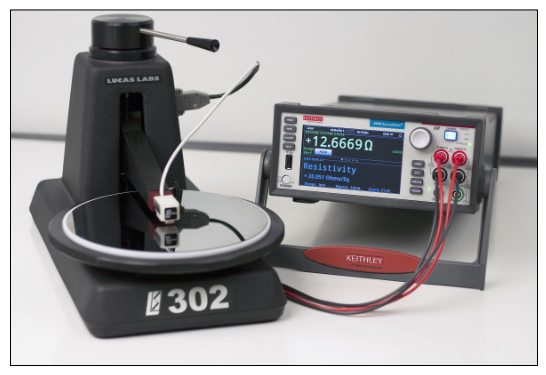
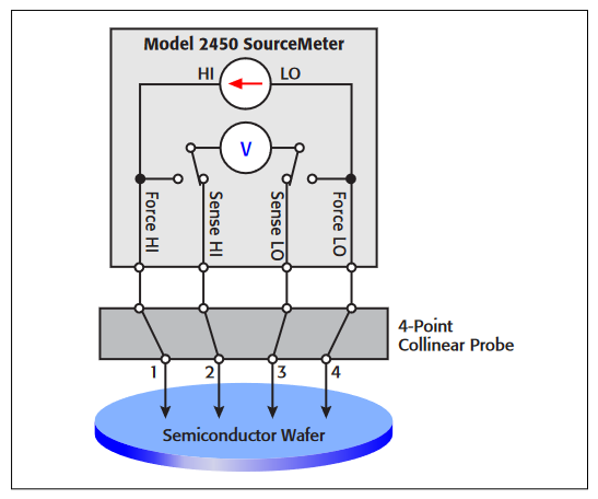
To simplify measurements, a single instrument, the Model 2450 SourceMeter® Source Measure Unit (SMU) Instrument, can be used. This instrument can source and measure both current and voltage and can be configured to display resistance or resistivity. The Model 2450 enables the user to choose a test current over many decades (from picoamps to amps), as well as measure voltage with resolution in the microvolt range. The Model 2450 is pictured in Figure 1 connected to a Signatone four-point collinear probe. This configuration is set up to measure the resistivity of a semiconductor wafer.
This application note explains how to perform resistivity measurements on materials using the Model 2450 and a fourpoint collinear probe.
The Four-Point Collinear Probe Method
The four-point collinear probe technique involves bringing four equally spaced probes in contact with a material of unknown resistance. The probes, mounted into a probe head, are gently placed in the center of the wafer as shown in the resistivity test circuit in Figure 2.
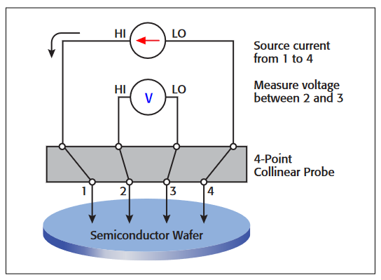
The two outer probes, 1 and 4, are used for sourcing current. The two inner probes, 2 and 3, are used for measuring the resulting voltage drop across the surface of the sample.
The volume or bulk resistivity (ρ) is calculated as follows:
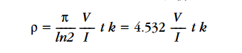
where:
ρ = the volume resistivity (Ω-cm)
V = the voltage measured between probes 2 and 3 (voltage)
I = the magnitude of the source current (amps)
t = the sample thickness (cm)
k = a correction factor based on the ratio of the probe to wafer diameter and on the ratio of wafer thickness to probe separation
For some materials such as thin films and coatings, the sheet resistance, or surface resistivity, is determined instead, which does not take the thickness into account. The sheet resistance (σ) is calculated as follows:

where:
σ = the sheet resistance (Ω/square or just Ω)
Note that the units for sheet resistance are expressed in terms of Ω/square in order to distinguish this number from the measured resistance (V/I).
Using the Kelvin Technique to Eliminate Lead and Contact Resistance
Using four probes eliminates measurement errors due to the probe resistance, the spreading resistance under each probe, and the contact resistance between each metal probe and the semiconductor material. Figure 3 is another representation of the four-point collinear probe setup that shows some of the circuit resistances.
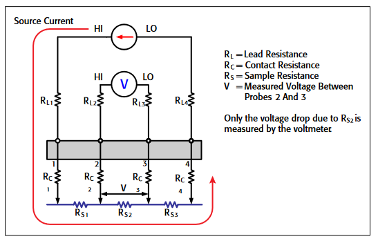
The RL terms represent the test lead resistance. RC represents the contact resistance between the metal probe and the semiconductor material. The contact resistance can be several hundred to a thousand times higher than the resistance of the sample material, which is represented by RS.
Notice that the current flows through all the resistances in the first and fourth set of leads and probes, as well as through the semiconductor material. However, the voltage is only measured between probes 2 and 3. Given that between probes 2 and 3, the current only flows through RS2, only the voltage drop due to RS2 will be measured by the voltmeter. All the other unwanted lead (R.L) and contact (RC) resistances will not be measured.
Using Compensation Techniques to Correct for Voltage Offsets
For increased accuracy, a technique to compensate for voltage offsets can be applied. There are two common methods of compensation to reduce voltage offsets: the offset compensation method and the current reversal method.
One method takes a voltage measurement at zero amps and then subtracts this value from a reading taken at the desired test current. This method is called offset compensation and is an option that can be performed automatically in the resistance mode of the Model 2450.
The other technique, the current reversal method, is similar to the other method but offers better signal to noise ratio. This technique cancels voltage offsets by making two measurements with currents of opposite polarity. When the two measurements are averaged, the voltage offsets are mathematically eliminated from the final result. This technique can be performed using software to control the Model 2450 or by downloading a script.
More information on either of these two methods can be found in Keithley's Low Level Measurement Handbook, available at www.keithley.com.
Making Connections to the Four-Point Probe
The four-point probe can be connected to the Model 2450 using either the front panel banana jacks or the rear panel triax connectors. A circuit diagram showing the Model 2450 connected to the four-point probe is shown in Figure 4. The Force terminals are connected to probes 1 and 4, and the Sense terminals are connected to probes 2 and 3. The rear panel triax terminals should be used for higher impedance materials. In this case, all cables, the probes, and the sample should also be electrostatically shielded. Some materials are photo sensitive and would require that the material be light shielded during the measurement.
Configuring the Test
After the probe is connected to the input terminals of the Model 2450 and the sample is placed on the mounting chuck, follow these steps to measure the resistivity of a sample:
- On the Model 2450, press the FUNCTION key and select Source Current and Measure Resistance (or Voltage). Choose the desired source current and voltage source limit (compliance) by using the front panel touch buttons. Set the Sense Mode to 4-Wire by pressing the MENU key, Measuring Settings, and then Sense Mode button
- Lower the probe head so the pins are in contact with the sample.
- Turn on the output of the Model 2450 and observe the reading. If the readings appear unstable, try increasing the test current. Make sure that the voltage drops between Force HI and Sense HI and also between Force LO and Sense LO do not exceed 5V.
- Calculate the resistivity from the readings
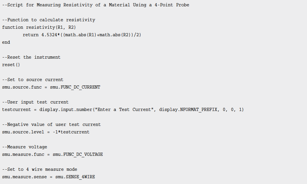
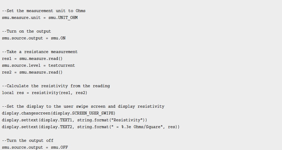
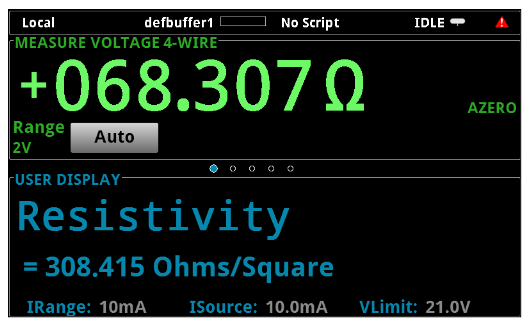
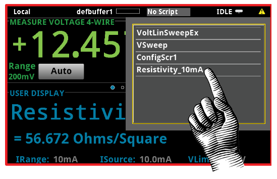
The resistivity can be automatically calculated using either the built-in "mx+b" Math Function or by using a script. A script is a list of commands that can be downloaded into the Model 2450. The results of executing a simple script to calculate the resistivity in ohms/square from the measured resistance are shown in Figure 5. Notice the calculated resistivity is displayed in the bottom half of the touchscreen.
Creating and Downloading Scripts to the Model 2450
To correct for voltage offsets by performing current reversals or to display the measurements with units of Ω/square or Ω-cm, you can easily create and download a script to the Model 2450. A script is a collection of TSP commands that you can download to the instrument using a USB drive. The scripts are executed from the front panel and are stored in non-volatile memory. These can be added or deleted from a front panel menu
An example script to perform resistivity measurementsis listed in Appendix A. In this script, the Model 2450 is programmed to perform a current reversal compensation technique using a user-prompted test current to measure the resistance. Then, the surface resistivity in ohms/square is calculated and displayed on the bottom half of the front panel. The results of executing the script are shown in. Figure 5.
Steps to Generate, Download, and Execute a Script
Here are the simple steps to create and execute a script on the Model 2450:
- By using either Notepad or Test Script Builder (TSB) Software, create a script to perform a resistivity measurement using the TSP command set. TSB is a software tool included with the Model 2450 that will enable you to execute the script before you download it to the unit. For your convenience, you can copy the script listed in this application note and modify it.
- Save the script as a .tsp file on a USB drive, and insert the USB drive into the Model 2450 front panel USB port.
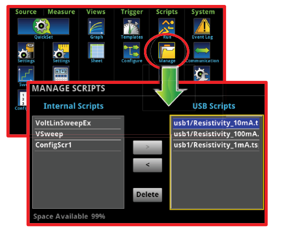
- Once the USB drive is inserted, all .tsp files on it will appear in the MANAGE SCRIPTS window. This can be accessed by pressing the MENU key and then Manage Scripts as shown in Figure 6. Press on the desired USB script and press the "<" key to add it to the Internal Scripts list.
- Once the script is stored into internal memory, the user can execute the script from the Home Page as shown in Figure 7. At the top of the Home Page, press the "No Script" button to view the available scripts. Press the desired script and the test will automatically execute.
Conclusion
The Model 2450 SourceMeter SMU Instrument is an ideal tool for measuring resistivity on samples using the four-point collinear probe method. This SMU instrument can source current and measure voltage or resistance using a four-wire method to prevent the lead and contact resistance from affecting the measurement. The Model 2450 enables the user to specify the test current, measure the resistance using offset compensation, calculate the resistivity, and shows the results on the display of the instrument.
Appendix A