The transient nature of radar pulses combined with modern pulse compression schemes demand carefully designed test setups. Another important consideration is the fact that most fundamental pulse measurements are timing-related, and these can be hard to get right without the proper set up. In this follow up to my previous post on understanding radar basics, I look at what’s involved with analyzing radar signals.
Pulse width and period are the fundamental parameters, corresponding to repetition rate and duty cycle. Pulse shaping is often used to contain the transmitted spectrum, which requires additional measurements to characterize. The pulse shape includes the rise time, fall time, and other unintended aberrations of the signal. The aberrations include overshoot, undershoot, ringing, and droop. An important measurement challenge is to measure the transient splatter and spectral re-growth when the pulse shaping is not as intended.
Timing variation from one pulse to the next is another important timing measurement. There may be intentional or unintentional variations degrading expected system performance and it’s important to be able to measurement these changes over many pulses.
Radar signals may also contain modulations within each pulse. Pulse modulations can be simple (e.g. BPSK or QPSK) or very complex (M-ary QAM or hopping). There are several common ways to measure modulations within a pulse.
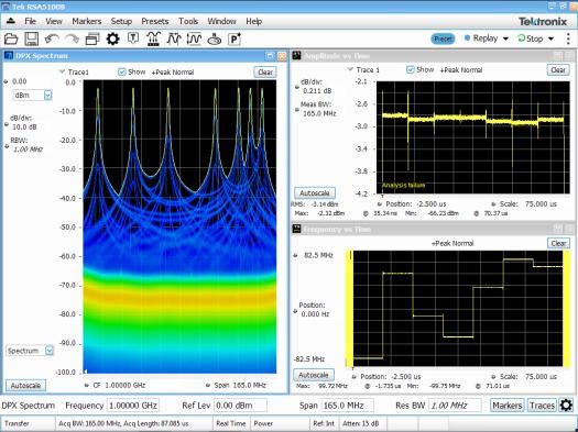
Amplitude, phase, and frequency versus time are all single parameter measurements. They operate on a sample-by-sample basis. An amplitude measurement plots the magnitude envelope detection. The magnitude is calculated for each sample by squaring both In-phase (I) and Quadrature (Q) values for each sample in sequence, summing them and then taking the square root of the sum.
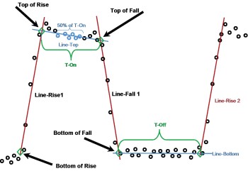
It is important to choose your measurement parameters carefully as there are several that must be set correctly before measurements are attempted. These affect the processing of pulsed signals, and are dependent on the character of the signal, as well as the desired interaction of the instrument with the incoming pulses. For example, all timing measurements are made with reference to the cardinal points.
For continuous-wave (CW) pulses, a frequency measurement can be made using a marker on a spectrum display, However, this method may have limitations due to the PRF lines and the ability to locate the center depending on space interpolation and signal repeatability. In our Analyzing Radar Signals Primer we look at a variety of methods to find the carrier frequency within pulses in preparation for the automated measurement of all the phase and frequency parameters:
- Pulse-to-pulse measurements
- Pulse-to-pulse carrier phase difference
- SNR effects on pulse-to-pulse phase
- Phase noise effects on pulse-to-pulse phase
- Pulse leading edge effects on pulse-to-pulse phase
- Overshoot effects on pulse-to-pulse phase
- Pulse-to-pulse carrier frequency difference.
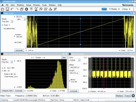
Chirp measurements require verification of the performance of frequency chirped pulses. For simple time-of-flight pulsed CW radar, the main concern are the timing parameters of the pulse. For chirped radar, transmit errors may cause subtle receiver errors. Parameters such as pulse timing, center frequency, chirp frequency width, and frequency errors across the chirp will cause problems when added to the radiated transmitter signal. Phase stability within and across pulses contribute to the fidelity of the entire radar system.
Designing effective modern radars can be a difficult and demanding task. Tektronix provides expertise and innovative solutions to help you meet the challenge. Our solutions enable you to see aspects of your signals that were previously invisible.
Our wideband signal analyzers offer real-time spectrum analysis with up to 800 MHz bandwidth and streaming storage of up to 2 hours of seamless data at full bandwidth. Tektronix solutions allow you to validate transmitter designs with speed and confidence using features like a live RF display and an advanced pulse measurement suite.
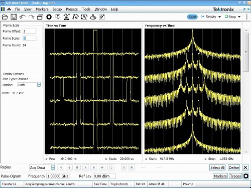
Electronic countermeasure (ECM) techniques are used to confuse a radar system by distorting, adjusting or fabricating one aspect of the pulse measurements, whether it's pulse width, frequency or phase characteristics, PRI, chirp pattern, number of targets, etc. Pulse-ogram analysis software helps you understand normal radar behavior and identify ECM techniques that require the analysis of multiple pulses simultaneously in both the frequency domain and time domain.
Want to learn more about analyzing radar signals? Download our Analyzing Radar Signals primer now. We’ve also posted another blog on understanding radar technology, applications and testing basics that you can read here.


